YOKOGAWA ZR202G User Manual
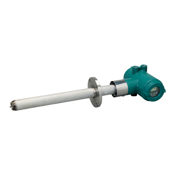
Integrated type zirconia oxygen analyzer
Hide thumbs
Also See for ZR202G:
- User manual (181 pages) ,
- General specifications (37 pages) ,
- User manual (241 pages)

Related Manuals for YOKOGAWA ZR202G


Summary of Contents for YOKOGAWA ZR202G
- Page 1 User’s Manual Model ZR202G Integrated type Zirconia Oxygen Analyzer IM 11M12A01-04E IM 11M12A01-04E 7th Edition...
-
Page 2: Introduction
Dust Filter for the detector (Part No. K9471UA) — Dust Guard Protector (Part No. K9471UC) ZO21S Standard Gas Unit CMPL: Customer Maintenance Parts List Media No.IM 11M12A01-04E (CD) 7th Edition :March 2012 (YK) IM 11M12A01-04E All Rights Reserved Copyright © 2000, Yokogawa Electric Corporation... - Page 3 <Introduction> This manual consists of twelve chapters. Please refer to the reference chapters for installation, opera- tion and maintenance. Relates to Chapter Outline Installation Operation Maintenance 1. Overview Equipment models and system configuration examples 2. Specifications Standard specification, model code (or part number), dimension drawing for each equipment 3.
-
Page 4: For The Safe Use Of This Equipment
Every effort has been made to ensure accuracy in the preparation of this manual. However, should any errors or omissions come to the attention of the user, please contact the nearest Yokogawa Electric representative or sales office. This manual does not cover the special specifications. This manual may not be changed on any change of specification, construction and parts when the change does not affect the functions or performance of the product. - Page 5 <Introduction> (2) Safety and Modification Precautions Follow the safety precautions in this manual when using the product to ensure protection and safety of personnel, product and system containing the product. The following safety symbols and wordings are used on the product as well as in this manual. (3) The following safety symbols are used in this manual.
- Page 6 <Introduction> Special descriptions in this manual This manual indicates operation keys, displays and drawings on the product as follows: • Operation keys, displays on the panel Enclosed in [ ]. (Ex. "MODE" key) (Ex. message display → "BASE") (Ex. data display →...
-
Page 7: Notice
Batteries are included in this product. Batteries incorporated into this product cannot be removed by yourself. Dispose them together with this product. When you dispose this product in the EU, contact your local Yokogawa Europe B.V.office. Do not dispose them as domestic household waste. -
Page 8: After-Sales Warranty
• Any damage from fire, earthquake, storms and floods, lightning, disturbances, riots, warfare, radiation and other natural changes. Yokogawa does not warrant conformance with the specific application at the user site. Yokogawa will not bear direct/indirect responsibility for damage due to a specific application. - Page 9 viii <Introduction> IM 11M12A01-04E...
-
Page 10: Table Of Contents
2.1 General Specifications ..................2-1 2.1.1 Standard Specifications ..............2-1 2.1.2 ZR202G Integrated type Zirconia Oxygen Analyzer ......2-2 2.1.3 ZO21R Probe Protector ..............2-9 ZA8F Flow Setting Unit and ZR20H Automatic Calibration Unit ....2-10 2.2.1 ZA8F Flow Setting Unit ..............2-10 2.2.2... - Page 11 Toc-2 <CONTENTS> Installation ....................3-1 Installation of ZR202G Zirconia Oxygen Analyzer ........3-1 3.1.1 Installation Location ................3-1 3.1.2 Probe Insertion Hole ................3-2 3.1.3 Installation of the Probe ..............3-2 3.1.4 Installation of the Dust Filter (K9471UA), Dust Guard Protector (K9471UC) Probe Protector (ZO21R) ..........
- Page 12 5.5.1 Cable Specifications ................5-5 5.5.2 Wiring Procedure ................5-6 Components ..................... 6-1 ZR202G Zirconia Oxygen Analyzer ..............6-1 6.1.1 Integrated type Zirconia Oxygen Analyzer ........6-1 ZA8F Flow Setting Unit, ZR20H Automatic Calibration Unit ......6-2 Startup ....................... 7-1 Checking Piping and Wiring Connections .............
- Page 13 Toc-4 <CONTENTS> Detailed Data Setting ................8-1 Setting Display Item ..................8-1 Current Output Setting ..................8-1 8.2.1 Setting Minimum Oxygen Concentration ( at 4 mA) and Maximum Oxygen Concentration ( at 20 mA) ............ 8-2 8.2.2 Entering Output Damping Constants ..........8-2 8.2.3 Selection of Output Mode ..............
- Page 14 Toc-5 <CONTENTS> Other Functions ..................10-1 10.1 Detailed Display ....................10-1 10.1.1 Air Ratio.................... 10-3 10.1.2 Cell Temperature ................10-3 10.1.3 C. J. Temperature................10-3 10.1.4 Amount of Water Vapor in Exhaust Gas .......... 10-3 10.1.5 Cell Voltage ..................10-4 10.1.6 Thermocouple Voltage ..............
- Page 15 Toc-6 <CONTENTS> 11.2 Inspection and Maintenance of the Converter ..........11-8 11.2.1 Replacing Fuses ................11-8 11.3 Replacement of Flowmeter for ZR20H Automatic Calibration Unit ..11-10 Troubleshooting ..................12-1 12.1 Displays and Measures to Take When Errors Occur ........12-1 12.1.1 What is an Error? ................
-
Page 16: Overview
(air) which is fed in at the installation site. The ZO21S standard gas unit is used for calibration. Zero gas from this unit and span gas (air) is sent to the probe through a tube which is connected during calibration. ZR202G Integrated type Zirconia Oxygen Analyzer Stop valve 100 to 240 V AC Contact input... -
Page 17: System 2
Zero gas is fed from a cylinder during calibration. The gas flow is controlled by the ZA8F flow setting unit (for manual valve operation). ZR202G Integrated type Zirconia Oxygen Analyzer Stop valve... -
Page 18: System 3
A “combustible gas detected” contact input turns off power to the heater. There’s also contact output from the converter that can be used to operate a purge gas valve to supply air to the sensor. ZR202G Integrated type Zirconia Oxygen Analyzer □... -
Page 19: Exaxt Zr > System Components
G7001ZC Zero gas Cylinder G7013XF, G7014XF Pressure Regulator for Gas Cylinder E7044KF Case Assembly for Calibration gas Cylinder ZR202A Heater Assembly (Spare Parts for ZR202G) T1.1.ai : Items required for the above system example : To be selected depending on each application. For details, refer to corresponding chapter. -
Page 20: Specifications
Standard Specifications Measured Object: Oxygen concentration in combustion exhaust gas and mixed gas (excluding inflammable gases). May not be applicable corrosive gas such as ammonia, chlorine is present-check with YOKOGAWA.) Measured System: Zirconia system Oxygen Concentration: 0.01 to 100 vol% O Output Signal: 4 to 20 mA DC (maximum load resistance 550Ω) -
Page 21: Zr202G Integrated Type Zirconia Oxygen Analyzer
Response of 90% within 5 seconds. (Measured after gas is introduced from calibration gas inlet and analog output starts changing.) 2.1.2 ZR202G Integrated type Zirconia Oxygen Analyzer Can be operated in the field without opening the cover using optical switches. Display:... - Page 22 <2. Specifications> Safety and EMC conforming standards Safety: EN61010-1, CSA C22.2 No.61010-1, UL61010-1 EMC: EN 61326 Class A, EN 55011 Class A Group 1, EN 61000-3-2, AS/NZS CISPR 11 KC Marking: Korea Electromagnetic Conformity Standard CAUTION This instrument is a Class A product, and it is designed for use in the industrial environment. Please use this instrument in the industrial environment only.
- Page 23 <2. Specifications> Functions Display Function: Displays values of the measured oxygen concentration, etc. Alarm, Error Display: Displays alarms such as “AL-06” or errors such as “Err-01” when any such status occurs. Calibration Functions: Auto-calibration; Requires the Automatic Calibration Unit. It calibrates automatically at specified intervals.
- Page 24 <2. Specifications> Converter Output: One mA analog output point (4 to 20 mA DC (maximum load resistance of 550Ω)) with mA digital output point (HART) (minimum load resistance of 250Ω). Range; Any setting between 0 to 5 through 0 to 100 vol% O in 1 vol% O and partial range is available (Maximum range value/minimum range value 1.3 or more)
- Page 25 Description ZR202G - - - - - - - - - - - - - - - - - - - - - - - - - - - - - - - - - - - - - -...
- Page 26 <2. Specifications> • External Dimensions Model ZR202G Integrated type Zirconia Oxygen Analyzers Unit: mm 338 to 351 Ø123 Display side L= 0.4, 0.7, Rc1/4 or 1/4NPT 1.0, 1.5, 2.0, Reference gas inlet 2.5, 3.0 (m) 153 to 164 4-G1/2,2-1/2NPT etc.
- Page 27 <2. Specifications> Model ZR202G...-P Integrated type Zirconia Oxygen Analyzer with pressure compensation Unit: mm 342 ± 4 Ø123 Display side L= 0.4, 0.7, Rc1/4 or 1/4NPT 1.0, 1.5, 2.0, Reference gas inlet 2.5, 3.0 (m) Reference gas outlet PIPING 4-G1/2,2-1/2NPT etc.
-
Page 28: Zo21R Probe Protector
10 m/sec. When probe length of the ZR202G is 2.5 m or more and mounted horizontally, be sure to select a probe protector ZO21R-L-200-*B to support the probe. -
Page 29: Za8F Flow Setting Unit And Zr20H Automatic Calibration Unit
300 kPa) (pressure at inlet of the automatic calibration unit) Air Consumption: Approx. 1.5 l/min Weight: Approx. 2 kg NOTE Used instrument air for span calibration gas, if without instrument air is used, contact YOKOGAWA. • Model and Codes Model Suffix code Option code Description ZA8F... - Page 30 2-11 <2. Specifications> • External Dimensions Unit : mm (inch) ø6 Hole REFERENCE CHECK REFERENCE SPAN ZERO 2B mounting pipe 235.8 222.8 Calibration gas outlet Span gas inlet Reference gas outlet Zero gas inlet Piping connection port A CHECK SPAN ZERO Model Piping connection port A...
-
Page 31: Zr20H Automatic Calibration Unit
(System 3). • Specifications Equipped with the analyzer when automatic calibration is specified in the suffix code of the ZR202G Integrated type by selecting either “-A (Horizontal mounting)” or “-B (Vertical mounting)”. The ZR20H should be arranged when automatic calibration is to be required after the ZR202G has been installed. - Page 32 SUFFIX STYLE SUPPLY 690kPa MAX. SPAN IN REF IN ZERO IN AMB.TEMP -20 TO 558C USED WITH ZR202G 66.5 166.5 Zero gas inlet Rc1/4 or 1/4NPT(Female) Reference gas inlet Rc1/4 or 1/4NPT(Female) Span gas inlet Rc1/4 or 1/4NPT(Female) PIPNG INSIDE THE AUTOMATIC CALIBRATION UNIT...
-
Page 33: Zo21S Standard Gas Unit
2-14 <2. Specifications> ZO21S Standard Gas Unit This is a handy unit to supply zero gas and span gas to the detector in a system configuration based on System 1. It is used in combination with the detector only during calibration. •... -
Page 34: Other Equipment
2-15 <2. Specifications> Other Equipment 2.4.1 Dust Filter for Oxygen Analyzer (part no. K9471UA) This filter is used to protect the detector sensor from corrosive dust components or from a high concentration of dust when the oxygen concentration in utility boilers or concrete kilns are to be measured. -
Page 35: Stop Valve (Part No. L9852Cb Or G7016Xh)
2-16 <2. Specifications> 2.4.3 Stop Valve (part no. L9852CB or G7016XH) This valve is mounted on the calibration gas line in the system to allow for one-touch calibration. This is applied to a system configuration (System 1). • Standard Specification Connection: Rc 1/4 or 1/4 FNPT Material:... -
Page 36: Air Set
2-17 <2. Specifications> 2.4.5 Air Set This set is used to lower the pressure when instrument air is used as the reference and span gases. Standard Specifications • Part no. G7003XF or K9473XK Primary Pressure: Max. 1 MPa G Secondary Pressure: 0.02 to 0.2 MPa G Connection: Rc1/4 or 1/4FNPT with joint adapter Weight: Approx.1 kg Part No. -
Page 37: Zero Gas Cylinder (Part No. G7001Zc)
2-18 <2. Specifications> 2.4.6 Zero Gas Cylinder (part no. G7001ZC) The gas from this cylinder is used as the calibration zero gas and detector purge gas. • Standard Specifications Capacity: 3.4 l Filled pressure: 9.8 to 12 MPa G Composition: 0.95 to 1.0 vol% O remaining N (Note) Export of such high pressure filled gas cylinder to most countries is prohibited or restricted. -
Page 38: Case Assembly (E7044Kf) For Calibration Gas Cylinder
- - - - - - - - - - - Always -A Suffix code of length should be selected as same as ZR202G installed. Jig part no. is K9470BX to order as a parts after purchase. (Note) The heater is made of ceramic, do not drop or subject it to pressure stress. - Page 39 Blank Page...
-
Page 40: Installation
(4) No vibration. (5) The sample gas satisfies the specifications described in Chapter 2. (6) No sample gas pressure fluctuations. CAUTION • The ambient temperature of the ZR202G Integrated type Zirconia Oxygen Analyzer should be between - 20°C and 55°C. IM 11M12A01-04E... -
Page 41: Probe Insertion Hole
<3. Installation> 3.1.2 Probe Insertion Hole CAUTION • The outside dimension of detector may vary depending on its options. Use a pipe that is large enough for the detector. Refer to Figure 3.1 for the dimensions. If the detector is mounted horizontally, the calibration gas inlet and reference gas inlet should face downwards. -
Page 42: Installation Of The Dust Filter (K9471Ua), Dust Guard Protector (K9471Uc) Probe Protector (Zo21R)
<3. Installation> The following should be taken into consideration when mounting the general-use detector: <General-use detector> (1) Make sure that the cell mounting screws (four bolts) at the probe tip are not loose. If a dust filter (see Section 2.4.1) is used, make sure it is properly attached to the detector. Refer to Section 3.1.4 for installation of the dust filter. - Page 43 < Procedures for installing the dust guard protector (K9471UC)> The ZR202G is shipped with the dust guard protector when the option code /F2 is specified in case of ordering the detector. The protector should be used when preventing dusts and water drops from lowering the detector performance is desired.
-
Page 44: Installation Of Za8F Flow Setting Unit
Mounting of detector with a probe protector (Dust wear protect) NOTE When the probe protector is used in the ZR202G with pressure compensation (-P), instrument air leaking from the probe protector may affect the measured value. Installation of ZA8F Flow Setting Unit 3.2.1... -
Page 45: Mounting Of Za8F Flow Setting Unit
<3. Installation> 3.2.2 Mounting of ZA8F Flow Setting Unit The flow setting unit can be mounted either on a pipe (nominal JIS 50 A) or on a wall. It should be positioned vertically so that the flowmeter works correctly. <Pipe Mounting> (1) Prepare a vertical pipe of sufficient strength (nominal JIS 50A: O.D. -
Page 46: Installation Of Zr20H Automatic Calibration Unit
Mounting of ZR20H Automatic Calibration Unit ZR202G - - - - - A or B is shipped with automatic calibration unit attached. The automatic calibration unit includes flowmeters and solenoid valves, so as to ensure reliable and accurate operation –... - Page 47 <3. Installation> Unit: mm Horizontal mounting on the ZR202G (-A) Display side Terminal box side Zero gas inlet Rc1/4 or 1/4NPT(Female) 66.5 166.5 Reference gas inlet Span gas inlet Rc1/4 or 1/4NPT(Female) Rc1/4 or 1/4NPT(Female) Vertical mounting on the ZR202G (-B) 166.5...
-
Page 48: Installation Of The Case Assembly (E7044Kf) For Calibration Gas Cylinder
<3. Installation> Installation of the Case Assembly (E7044KF) for Calibration Gas Cylinder The case assembly is used to store the G7001ZC zero gas cylinders. 3.4.1 Installation Location The following should be taken into consideration: (1) Easy access for cylinder replacement (2) Easy access for checking (3) Near to the detector and converter as well as the flow setting unit. -
Page 49: Insulation Resistance Test
3-10 <3. Installation> Insulation Resistance Test Even if the testing voltage is not so great that it causes dielectric breakdown, testing may cause deterioration in insulation and a possible safety hazard. Therefore, conduct this test only when it is necessary. The applied voltage for this test shall be 500 V DC or less. -
Page 50: Piping
• When the instrument applies natural convection for reference gas (Model ZR202G----- C), ambient air near the probe is used for reference gas; therefore the accuracy of analysis will be affected by ambient humidity changes or the like. -
Page 51: Piping Parts For System 1
Mount the stop valve (of a quality specified by YOKOGAWA) through a nipple (found on the local market) as illustrated in Figure 4.2, and mount a joint (also found on the local market) at the stop valve tip. (The stop valve may be mounted on the equipment when the oxygen analyzer is shipped.) -
Page 52: Piping For System 2
Mount the pressure regulator (recommended by YOKOGAWA) on the cylinder. Mount the stop valve or the check valve (recommended by YOKOGAWA) through the nipple (found on the local market) at the calibration gas inlet of the equipment as illustrated in Figure 4.8. (The stop valve or the check valve may have been mounted on the equipment when shipped.) Connect the... -
Page 53: Piping For The Calibration Gas
Next check span gas calibration contact output and adjust air set so that span gas flow is within the permitted range. ZR202G Integrated type Zirconia Oxygen Analyzer with automatic calibration 100 to 240 V AC... - Page 54 <4. Piping> • Installation of ZR20H Automatic Calibration Unit Unit: mm Horizontal mounting on the ZR202G (-A) Display side Terminal box side Zero gas inlet Rc1/4 or 1/4NPT(Female) 66.5 166.5 Reference gas inlet Span gas inlet Rc1/4 or 1/4NPT(Female) Rc1/4 or 1/4NPT(Female) Vertical mounting on the ZR202G (-B) 166.5...
-
Page 55: Piping For The Oxygen Analyzer With Pressure Compensation
Piping for the Oxygen Analyzer with Pressure Compensation ZR202G-----P Oxygen Analyzer with pressure compensation may be used in System 2 and System 3. Use this style analyzer whenever the furnace pressure exceeds 5 kPa (see Note). Even if the furnace pressure is high, the detector can measure by adjusting pressure of the probe with the furnace pressure using instrument air. - Page 56 Figure 4.13 illustrates an example of System 2 using the analyzer with pressure compensation. Supplying the air pressure (flow) may vary depending on the furnace pressure. It is recommended to use a flow gauge and an air set meeting the furnace pressure. ZR202G Integrated type Zirconia Oxygen Analyzer with pressure compensation Stop valve...
-
Page 57: Piping Parts For Oxygen Analyzer With Pressure Compensation
Parts Name Description Oxygen Analyzer Calibration gas inlet Check valve or stop Stop valve (L9852CB or G7016XH) with pressure valve recommended by YOKOGAWA compensation Check valve (K9292DN or K9292DS) provided by YOKOGAWA Nipple * Rc1/4 or 1/4 NPT General parts... -
Page 58: Wiring
<5. Wiring> Wiring This chapter describes wiring procedures necessary for the EXAxt ZR Integrated type Zirconia Oxygen Analyzer. General CAUTION • Never supply current to the equipment or any other device constituting a power circuit in combination with the equipment, until all wiring is completed. •... -
Page 59: Terminals For The External Wiring
Make the following wiring for the equipment. It requires a maximum of four wiring connections as shown below. (1) Analog output signal (2) Power and ground (3) Contact output (4) Contact input Model ZR202G Integrated type Zirconia Oxygen Analyzer Contact output 1 Contact output 2 Contact input 1 Contact input 2 DI-1... -
Page 60: Mounting Of Cable Gland
<5. Wiring> 5.1.3 Mounting of Cable Gland For each wiring inlet connection of the equipment, mount the conduit appropriate for the screw size or a cable gland. Rc1/4 or 1/4NPT Reference gas inlet Cable gland Rc1/4 or 1/4NPT Calibration gas inlet 4-G1/2,2-1/2NPT etc. -
Page 61: Wiring Power And Ground Terminals
<5. Wiring> Wiring Power and Ground Terminals Wiring for supplying power to the analyzer and grounding the equipment. Ground Grounding to the earth terminal on the equipment case Equipment case Crimp contact of Jumper plate the grounding line Lock washer Grounding terminal 100~240VAC... -
Page 62: Wiring For Contact Output
<5. Wiring> Wiring for Contact Output The equipment can output a maximum of two contact signals. These contact outputs can be used for different applications such as a low alarm or high alarm. Do the contact output wiring according to the following requirements. Analyzer Terminal box Annunciator or the like... -
Page 63: Wiring Procedure
<5. Wiring> 5.5.2 Wiring Procedure (1) M4 screws are used for the terminal of the converter. Each cable should be equipped with the corresponding crimp contact. (2) The ON/OFF level of this contact input is identified by the resistance. Connect a contact input that satisfies the descriptions in Table 5.2. -
Page 64: Components
<6. Components> Components This chapter describes the names and functions of components for the major equipment of the EXAxt ZR Integrated type Zirconia Oxygen Analyzer. ZR202G Zirconia Oxygen Analyzer 6.1.1 Integrated type Zirconia Oxygen Analyzer Terminal box, Non explosion-proof JIS C0920 / equivalent to IP44D. -
Page 65: Za8F Flow Setting Unit, Zr20H Automatic Calibration Unit
<6. Components> ZA8F Flow Setting Unit, ZR20H Automatic Calibration Unit Reference gas flow setting valve Span gas flow setting valve Zero gas flow setting valve Flowmeter for reference gas Flowmeter for calibration gas F6-4E.ai Figure 6.2 ZA8F Flow Setting Unit Horizontal mounting Vertical mounting Flowmeter for... -
Page 66: Startup
<7. Startup> Startup The following describes the minimum operating requirements — from supplying power to the converter to analog output confirmation to manual calibration. Check piping and Set output ranges wiring connections Set up valves Check current loop Supply power Check contact action Confirm converter Calibrate analyzer... -
Page 67: Checking Piping And Wiring Connections
<7. Startup> Checking Piping and Wiring Connections Refer to Chapters 4 and 5, earlier in this manual, for piping and wiring confirmations. Valve Setup Set up valves and associated components used in the analyzer system in the following procedures: (1) If a stop valve is used in the detector’s calibration gas inlet, fully close this valve. (2) If instrument air is used as the reference gas, adjust the Air set secondary pressure so that the air pressure of sample gas pressure plus approx. -
Page 68: Operation Of Infrared Switch
<7. Startup> Operation of Infrared Switch 7.4.1 Display and Switches This equipment uses an infrared switch that enables operation with the cover closed. Figure 7.3 shows the infrared switch and the display. Table 7.1 shows the three switch (keys) and functions. 4: Decimal point 1: Data display area µ... -
Page 69: Display Configuration
<7. Startup> CAUTION 1. Be sure to put the equipment case cover back on. If this is not done, the infrared switch will not reflect the infrared light-waves, and a “dSPErr” error will be issued. 2. Before placing the equipment in operation, be sure to wipe off any moisture or dust on the glass surface if it is wet or dirty. -
Page 70: Entering Parameter Code Selection Display
<7. Startup> Table 7.2 Display Functions Display Function and item to be set Basic panel Displays the oxygen concentration in normal operation, or displays the detector heater temperature while warming up. If an error or alarm arises, the corresponding error or alarm number appears. Password entry Enters the password for the parameter code selection display. -
Page 71: Selecting Parameter Codes
<7. Startup> 7.4.4 Selecting Parameter Codes Switch operation Display Description > ∧ Password has been entered and the parameter code selection display has appeared. Character A is flashing, indicating that character A can be changed. > ∧ If you touch the [>] key once, the position of the digit that is flashing will move to the right. - Page 72 <7. Startup> (2) Entering numeric values such as oxygen concentration values and factors Switch operation Display Description > ∧ 00.0 The set value is displayed after the parameter code selection. An example of entering "9.8" is given below. (The currently set value is 0.0) >...
-
Page 73: Confirmation Of Equipment Type Setting
<7. Startup> Confirmation of Equipment Type Setting This equipment can be used for both the Oxygen Analyzer and the Humidity Analyzer. If you choose optional specification /HS at the time of purchase, the equipment is set for the Humidity Analyzer. Before setting the operating data, be sure to check that the desired model has been set. -
Page 74: Selection Of Measurement Gas
<7. Startup> Selection of Measurement Gas Combustion gases contain moisture created by burning hydrogen in the fuel. If this moisture is removed, the oxygen concentration might be higher than before. You can select whether the oxygen concentration in a wet gas is to be measured directly, or compensated for its dry-gas value before use. Use the parameter code 「F02」... - Page 75 7-10 <7. Startup> Table 7.5 Minimum and Maximum Value Setting Procedure Switch operation Display Description > ∧ Display after the password has been entered. > ∧ Set the oxygen concentration at 4 mA. Change the parameter code to C11. Touch the [∧] key to switch to Group C. >...
-
Page 76: Checking Current Loop
7-11 <7. Startup> Checking Current Loop The set current can be output as an analog output. This enables the checking of wiring between the converter and the receiving instrument. Current loop checking is performed using parameter code 「G01」 . Table 7.6 Checking Current Loop Switch operation Display... -
Page 77: Contact Output Check
7-12 <7. Startup> 7.9.1 Contact Output Check Follow Table 7.8 to check the contact output. The table uses an example with contact output 1. Table 7.8 Checking Contact Output Switch operation Display Description > ∧ Display after the password has been entered. >... -
Page 78: Checking Calibration Contact Output
7-13 <7. Startup> 7.9.2 Checking Calibration Contact Output The calibration contacts are used for the solenoid valve drive signals for the Automatic Calibration Unit. This output signal enables you to check the equipment operation. Check the flowmeter gas flow for that operation. Follow the steps in Table 7.9. -
Page 79: Checking Input Contacts
7-14 <7. Startup> 7.9.3 Checking Input Contacts Follow Table 7.10 to check the input contacts. The table uses an example with input contact 1. Table 7.10 Checking Input Contacts Switch operation Display Description > ∧ Display after the password has been entered. >... -
Page 80: Calibration
7-15 <7. Startup> 7.10 Calibration The converter is calibrated in such a way that the actual zero and span gases are measured and those measured values are used to agree with the oxygen concentrations in the respective gases. There are three types of calibration procedures available: (1) Manual calibration conducting zero and span calibrations, or either of these calibrations in turn. - Page 81 7-16 <7. Startup> Table 7.12 Calibration Setup Procedure Switch operation Display Description > ∧ Display after the password has been entered. > ∧ Set the zero gas concentration. Switch the parameter code to B01. Here, set 0.98%. > ∧ 001.00 Touch the [ENT] key to display the currently set value.
-
Page 82: Manual Calibration
7-17 <7. Startup> 7.10.2 Manual Calibration The following describes how to conduct a calibration. 7.10.2.1 Preliminary Before conducting a manual calibration, be sure that the ZA8F Flow Setting Unit zero gas flow valve is fully closed. Open the zero gas cylinder pressure regulator so that the secondary pressure will be a sample gas plus approx. - Page 83 7-18 <7. Startup> Table 7.13 Conducting Calibration (Continued) Switch operation Display Description > ∧ ZEro If you touch the [ENT] key again, the flashing stops and "ZEro Y" appears. Close the span gas flow valve. Secure the span gas lock nut for leakage. If the automatic calibration unit is connected, close the span gas solenoid valve.
-
Page 84: Detailed Data Setting
<8. Detailed Data Setting> Detailed Data Setting Setting Display Item Display items are defined as items displayed on the basic panel display. Parameter code 「A00」 or 「F08」 is used to set the display items as shown in Table 8.1. The oxygen concentration is set at the factory before shipment. -
Page 85: Setting Minimum Oxygen Concentration ( At 4 Ma) And Maximum Oxygen Concentration ( At 20 Ma)
<8. Detailed Data Setting> 8.2.1 Setting Minimum Oxygen Concentration ( at 4 mA) and Maximum Oxygen Concentration ( at 20 mA) Set the oxygen concentration values at 4 mA and 20 mA. The minimum concentration of oxygen for the minimum current (4 mA) is 0% O or 6% to 76% O The maximum concentration of oxygen for the maximum current (20 mA) ranges from 5% to 100% , and must be greater than 1.3 times the concentration of oxygen set for the minimum. -
Page 86: Output Hold Setting
<8. Detailed Data Setting> Output Hold Setting The “output hold” functions retain an analog output signal at a preset value during the equipment’s warm-up time or calibration or if an error arises. Table 8.4 shows the analog outputs that can be retained and the individual states. Table 8.4 Analog Output Hold Setting Equipment status... - Page 87 <8. Detailed Data Setting> Switch operation Display > ∧ > ∧ > ∧ > ∧ SPAn > ∧ 21.00 > ∧ OPEn/20.84 > ∧ 20.84 > ∧ ZEro > ∧ 0.98 Output hold time Output hold time during calibration during calibration >...
-
Page 88: Preference Order Of Output Hold Value
<8. Detailed Data Setting> 8.3.2 Preference Order of Output Hold Value The output hold value takes the following preference order: During error occurrence During calibration Preference order (high) During maintenance During warm-up 8.3.2E.siki For example, if the output current is set to “4 mA” during maintenance, and “without hold” output during calibration is preset, the output is held at 4 mA in the maintenance display. -
Page 89: Setting Oxygen Concentration Alarms
<8. Detailed Data Setting> Setting Oxygen Concentration Alarms The analyzer enables the setting of four alarms high-high, high, low, and low-low alarms depending upon the oxygen concentration. The following section sets forth the alarm operations and setting procedures. 8.4.1 Alarm Values (1) High-high and high alarm values High-high alarms and high alarms are issued when they are set to be detected with parameter codes 「D41」... -
Page 90: Alarm Setting
<8. Detailed Data Setting> In the example in Figure 8.2, the high alarm point is set to 7.5% O , the delayed time is set to five seconds, and hysteresis is set to 2% O Alarm output actions in this figure are expressed as follows: (1) Although oxygen concentration measurement “A”... -
Page 91: Default Values
<8. Detailed Data Setting> 8.4.4 Default Values When the analyzer is delivered, or if data are initialized, the default alarm set values are as shown in Table 8.8. Table 8.8 Alarm Setting Default Values Set item Set value High-high alarm setpoint 100% O High alarm setpoint 100% O... -
Page 92: Setting Output Contact
<8. Detailed Data Setting> 8.5.2 Setting Output Contact Set the output contacts following Table 8.10. Table 8.10 Parameter Codes for Output Contact Setting Set item Parameter Set value code Output contact 1 Operation Operated in closed status. (Normally de-energized) Operated when open. (Normally energized) (Note 1) Error Not operated if an error occurs. -
Page 93: Default Values
8-10 <8. Detailed Data Setting> 8.5.3 Default Values When the analyzer is delivered, or if data are initialized, output contacts are by default as shown in Table 8.11. Table 8.11 Output Contact Default Settings Item Output contact 1 Output contact 2 High-high alarm High alarm Low alarm... -
Page 94: Input Contact Settings
8-11 <8. Detailed Data Setting> Input Contact Settings The converter input contacts execute set functions by accepting a remote (contact) signal. Table 8.12 shows the functions executed by a remote contact signal. Table 8.12 Input Contact Functions Set item Function Calibration gas pressure While a contact signal is on, neither semi-automatic nor automatic calibrations decrease... -
Page 95: Other Settings
8-12 <8. Detailed Data Setting> Other Settings 8.7.1 Setting the Date-and-Time The following describe how to set the date-and-time. Automatic calibration works following this setting. Use parameter code 「F10」 to set the date-and-time. Table 8.14 Data-and-time Settings Switch operation Display Description >... -
Page 96: Setting Periods Over Which Average Values Are Calculated And Periods Over Which Maximum And Minimum Values Are Monitored
8-13 <8. Detailed Data Setting> 8.7.2 Setting Periods over which Average Values are Calculated and Periods over which Maximum and Minimum Values Are Monitored The equipment enables the display of oxygen concentration average values and maximum and minimum values under measurement (see Section 10.1, later in this manual). The following section describes how to set the periods over which oxygen concentration average values are calculated and maximum and minimum values are monitored. -
Page 97: Setting Fuels
8-14 <8. Detailed Data Setting> 8.7.3 Setting Fuels 8.7.3.1 Input Parameters The analyzer calculates the moisture content contained in exhaust gases. The following sets forth the fuel parameters necessary for calculation and their entries. The moisture quantity may be mathematically expressed by: (water vapor caused by combustion and water vapor contained in the exhaust gas) + (water vapor contained in air for combustion) .. - Page 98 8-15 <8. Detailed Data Setting> For liquid fuel Amount of water vapor in exhaust gas (Gw) = (1/100) {1.24 (9h + w)} (m /kg) Theoretical amount of air (Ao) = 12.38 x (Hl/10000) – 1.36 (m /kg) Low calorific power = Hl X value = (3.37 / 10000) x Hx –...
- Page 99 8-16 <8. Detailed Data Setting> 0.046 0.044 0.042 0.040 0.038 0.036 0.034 0.032 0.030 0.028 Wet-bulb 0.026 Absolute temperature, °C humidity, kg/kg 0.024 0.022 0.020 0.018 0.016 0.014 0.012 0.010 0.008 0.006 0.004 0.002 0.000 12 14 16 18 20 22 24 26 28 30 32 34 36 38 40 Dry-bulb temperature, °C...
- Page 100 8-17 <8. Detailed Data Setting> Table 8.16 Fuel Data For liquid fuel Fuel Chemical component Amount of combustion Calorific power Theoretical Specific properties amount of (weight percentage) gas Nm kJ/kg weight value air for kg/l combustion Type Higher Lower Total O SO content order...
-
Page 101: Setting Purging
8-18 <8. Detailed Data Setting> 8.7.3.2 Procedure Use the parameter code table below to set fuel values. Table 8.17 Setting Fuel Values Set item Parameter code Set value Engineering units Amount of water vapor in 0 to 5 /kg (m exhaust gas Theoretical amount of air 1 to 20... -
Page 102: Calibration
<9. Calibration> Calibration Calibration Briefs 9.1.1 Principle of Measurement This section sets forth the principles of measurement with a zirconia oxygen analyzer before detailing calibration. A solid electrolyte such as zirconia allows the conductivity of oxygen ions at high temperatures. Therefore, when a zirconia-plated element with platinum electrodes on both sides is heated up in contact with gases having different oxygen partial pressures on each side, the element shows the action of the concentration cell. -
Page 103: Calibration Gas
<9. Calibration> 0.51 vol%O ,81.92mV(Zero origin of calibration) Cell voltage (mV) 21.0 vol%O , 0mV (Span origin of calibration) 21.0 Oxygen concentration (vol % O F9.1E.ai Figure 9.1 Oxygen Concentration in a Measurement Gas vs. Cell Voltage (21 vol%O Equivalent) The measurement principles of a zirconia oxygen analyzer have been described above. - Page 104 <9. Calibration> 81.92 Zero origin Calibration curve before correction Cell electromotive force, mV Corrected calibration curve (theoretical calibration curve) Span origin 21.0 0.51 Zero gas concentration Span gas concentration Oxygen concentration (vol%O Zero correction ratio = (B/A) x 100 (%) Correctable range: 100 ±...
-
Page 105: Characteristic Data From A Sensor Measured During Calibration
<9. Calibration> 9.1.4 Characteristic Data from a Sensor Measured During Calibration During calibration, calibration data and sensor status data (listed below) are acquired. However, if the calibration is not properly conducted (an error occurs in automatic or semi-automatic calibration), these data are not collected in the current calibration. These data can be observed using parameter codes 「A20」... -
Page 106: Calibration Procedures
<9. Calibration> Calibration Procedures CAUTION Calibration should be made under normal operating conditions (if the probe is connected to a furnace, the analyzer will undergo calibration under the operating conditions of the furnace). To make a precise calibration, conduct both zero and span calibrations. 9.2.1 Calibration Setting The following sets forth the required calibration settings:... - Page 107 <9. Calibration> 9.2.1.4 Span gas Concentration Set the oxygen concentration for span calibration. If instrument air is used as the span gas, enter 21 When using the ZO21S Standard Gas Unit (for use of the atmospheric air as a span gas), use a hand- held oxygen analyzer to measure the actual oxygen concentration, and then enter it.
- Page 108 <9. Calibration> 9.2.1.6 Setting When setting calibration timing requirements, bear the following precautions in mind: CAUTION If the calibration interval is shorter than the sum of hold (output stabilization) time plus calibration time, the second calibration start time will conflict with the first calibration. In such a case, the second calibration will not be conducted.
-
Page 109: Calibration
<9. Calibration> 9.2.2 Calibration 9.2.2.1 Manual Calibration For manual calibration, consult Section 7.10, “Calibration,” earlier in this manual. 9.2.2.2 Semi-automatic Calibration (1) Calibration startup using infrared switches Table 9.3 Semi-automatic Calibration Procedure Switch operation Display Description > ∧ Change the parameter code to b11. (Previous operations omitted) >... -
Page 110: Other Functions
10-1 <10. Other Functions> 10. Other Functions 10.1 Detailed Display Select the desired parameter code to display the detailed operation data (see Table 10.1, “Parameter Codes for Detailed Operation Data”. NOTE Refer to Section 8.1, “Setting Display Item”, for parameter code 「A00」 . IM 11M12A01-04E... - Page 111 10-2 <10. Other Functions> Table 10.1 Parameter Codes for Detailed Operation Data Engineering Engineering Code Item Code Item unit unit Selection 0 Oxygen concentration Span correction ratio 0 of display 1 Oxygen analyzer (0.0) Span correction ratio 1 items 2 Oxygen analyzer (0.0) Span correction ratio 2 3 Analog output selected Span correction ratio 3...
-
Page 112: Air Ratio
If this temperature exceeds 85°C, the electronics may fail. When the ZR202G is used, the maximum C. J. temperature will be 150°C. If the internal temperature exceeds this, take measures to reduce the temperature such as by not exposing the equipment to radiation. -
Page 113: Cell Voltage
10-4 <10. Other Functions> 10.1.5 Cell Voltage The cell (sensor) voltage will be an index to determine the amount of degradation of the sensor. The cell voltage corresponds to the oxygen concentration currently being measured. If the indicated voltage approximates the ideal value (corresponding to the measured oxygen concentration), the sensor will be assumed to be normal. -
Page 114: Response Time
10-5 <10. Other Functions> 10.1.9 Response Time The cell’s response time is obtained in the procedure shown in Figure 10.1. If only either zero or span calibration has been carried out, the response time will not be measured just as it will not be measured in manual calibration. -
Page 115: Heater On-Time Ratio
10-6 <10. Other Functions> 10.1.12 Heater On-Time Ratio The probe sensor is heated to and maintained at 750°C. When the sample gas temperature is high, the amount of heater ON-time decreases. 10.1.13 Oxygen Concentration (with time constant) When the output damping is specified in the mA-output range setting, the corresponding time constant is also displayed. -
Page 116: History Of Calibration Time
10-7 <10. Other Functions> 10.1.18 History of Calibration Time The calibration-conducted dates and times for the past ten calibrations are stored in memory. 10.1.19 Time The current date and time are displayed. These are backed up by built-in batteries, so no adjustment is required after the power is switched off. -
Page 117: Initialization Procedure
10-8 <10. Other Functions> 10.3 Initialization Procedure Follow the table below to initialize parameters. The password for initialization is 1255. Table 10.5 Initialization Procedure Switch operation Display Description > ∧ Enter the parameter code for the item to be initialized. The following show an example of entering "F30."... -
Page 118: Reset
10-9 <10. Other Functions> 10.4 Reset Resetting enables the equipment to restart. If the equipment is reset, the power is turned off and then back on. In practical use, the power remains on, and the equipment is restarted under program control. - Page 119 10-10 <10. Other Functions> Table 10.6 Resetting Switch operation Display Brief Description > ∧ Err-01 If an error occurs, the error number and "------" are displayed alternately, /------ as given on the left. > ∧ PASSno Hold down the [ENT] key for at least three seconds. >...
- Page 120 10-11 <10. Other Functions> CAUTION • Parameters of blank item are not used for Oxygen Analyzer. Table 10.7 Parameter Codes Display-related Items in Group A Engineering Engineering Code Item Code Item unit unit Selection 0 Oxygen concentration Span correction ratio 0 of display 1 Oxygen analyzer (0.0) Span correction ratio 1...
- Page 121 10-12 <10. Other Functions> Calibration-related Items in Group B Code Item Tuning Engineering unit Default setting Zero gas concentration 0.3 to 100 1% O Span gas concentration 4.5 to 100 21% O Calibration mode 0 Manual calibration Manual calibration 1 Semi-automatic and manual calibration 2 Automatic, semi-automatic, and manual calibration...
- Page 122 10-13 <10. Other Functions> Output-related Items in Group C Code Item Tuning Engineering unit Default setting Analog output 0 Oxygen concentration Oxygen concentration 1 Amount of moisture content 2 Mixed ratio Output mode 0 Linear Linear 1 Logarithm Output during warm-up 0 Held at 4 mA 1 Held at 20 mA 2 Set value remains held.
- Page 123 10-14 <10. Other Functions> Contact-related Items in Group E Code Item Tuning Engineering unit Default setting Selection of input contact 1 0 Invalid Invalid 1 Calibration gas pressure decrease 2 Measurement range change 3 Calibration start 4 Detection of non-combusted gas Selection of input contact 2 0 Invalid Invalid...
- Page 124 10-15 <10. Other Functions> Equipment Setup and Others in Group F Code Item Tuning Engineering unit Default setting Equipment setup 0 Oxygen analyzer Oxygen analyzer 1 Humidity analyzer Selection of measurement 0 Wet 1 Dry Selection of temperature 0 degree C degree C units 1 degree F...
-
Page 125: Handling Of The Zo21S Standard Gas Unit
10-16 <10. Other Functions> 10.5 Handling of the ZO21S Standard Gas Unit The following describe how to flow zero and span gases using the ZO21S Standard Gas Unit. Operate the ZO21S Standard Gas Unit, for calibrating a system classified as System 1, according to the procedures that follow. -
Page 126: Calibration Gas Flow
10-17 <10. Other Functions> The operating details and handling precautions are also printed on the product. Please read them beforehand. To install the gas cylinder, follow these steps: (1) Attach the zero gas valves onto the gas cylinder. First, turn the valve regulator of the zero gas valves counterclockwise to completely retract the needle at the top from the gasket surface. - Page 127 10-18 <10. Other Functions> (2) Next, adjust the flow rate to 600 ± 60 ml/min using the span gas valve “AIR” (the flow check ball stops floating on the green line when the valve is slowly opened). To rotate the valve shaft, loosen the lock nut and turn it using a flat-blade screwdriver.
-
Page 128: Methods Of Operating Valves In The Za8F Flow Setting Unit
10-19 <10. Other Functions> 10.6 Methods of Operating Valves in the ZA8F Flow Setting Unit The ZA8F Flow Setting Unit is used as the calibration equipment for a system conforming to System 2. Calibration in such a system is to be manually operated. So, you have to operate the valve of the Flow Setting Unit each time calibration is made (starting and stopping the calibration gas flow and adjusting the flow rate). -
Page 129: Treatment After Calibration
10-20 <10. Other Functions> Table 10.9 Sample gas pressure, (kPa) Flow rate, (ml/min) (3) Adjust the flow rate. After the measured oxygen concentration is stabilized, touch the [ENT] key, then all the digits will flash. Touch the [ENT] key again to flash “CAL End.” (4) Close the zero gas flow setting valve to stop the zero gas flow. -
Page 130: Inspection And Maintenance
11-1 <11. Inspection and Maintenance> 11. Inspection and Maintenance This chapter describes the inspection and maintenance procedures for the EXAxt ZR Zirconia Oxygen Analyzer to maintain its measuring performance and normal operating conditions. CAUTION When checking the detector, carefully observe the following: (1) Do NOT touch the probe if it has been in operation immediately just before being checked. -
Page 131: Replacing The Sensor Assembly
11-2 <11.Inspection and Maintenance> Exploded view of components Calibration gas tube (with outside diameter of 2 to 2.5 mm) F11.1E.ai Figure 11.1 Cleaning the Calibration Gas Tube 11.1.2 Replacing the Sensor Assembly The performance of the sensor (cell) deteriorates as its surface becomes soiled during operation. Therefore, you have to replace the sensor when its life expectancy expires, for example, when it can no longer satisfy a zero correction ratio of 100 ±... - Page 132 11-3 <11. Inspection and Maintenance> (4) Use tweezers to pull the contact out of the groove. (5) Clean the sensor assembly, especially the metal O-ring contact surface to remove any contaminants adhering to that part. If you can use any of the parts from among those removed, also clean them up to remove any contaminants adhering to them.
-
Page 133: Replacement Of The Heater Assembly
11-4 <11.Inspection and Maintenance> Metal O-ring Sensor (cell) U-shaped pipe support Dust filter Bolts (four) (optional) Probe Contact Screw Filter U-shaped pipe Washers (four) 1/8 turn – tighten bolts 1/8 turn F11.3E.ai (approximately 45°) each Figure 11.3 Exploded View of Sensor Assembly CAUTION Optional Inconel bolts have a high coefficient of expansion. - Page 134 11-5 <11. Inspection and Maintenance> View A-A F11.4E.ai Figure 11.4 Exploded View of Detector IM 11M12A01-04E...
-
Page 135: Replacement Of Dust Filter
11-6 <11.Inspection and Maintenance> Replacement of heater assembly Refer to Figure 11.4 as an aid in the following discussion. Remove U-shaped pipe support ④, U-shaped pipe ⑤, Filter and the sensor (cell) ⑥, following Section 11.1.2, earlier in this manual. Remove the two screws ⑮... - Page 136 11-7 <11. Inspection and Maintenance> CAUTION When operating an instrument such as boiler or industrial furnace is stopped with the zirconia oxygen analyzer operation, moisture can condensate on the sensor portion and dusts may stick to it. If operation is restarted in this condition, the sensor which is heated up to 750°C firmly fixes the dusts on itself.
-
Page 137: Inspection And Maintenance Of The Converter
11-8 <11.Inspection and Maintenance> 11.2 Inspection and Maintenance of the Converter The converter does not require routine inspection and maintenance. If the converter does not work properly, in most cases it probably comes from problems or other causes. 11.2.1 Replacing Fuses This equipment incorporates a fuse. - Page 138 11-9 <11. Inspection and Maintenance> (7) To restore the electronics, reverse the above removal procedures. When restoring the electronics, do not get leadwire jammed in any part of the unit. (8) Place the electronics and the printed-circuit board on which the fuse is installed properly; these are directly connected with connectors.
-
Page 139: Replacement Of Flowmeter For Zr20H Automatic Calibration Unit
11-10 <11.Inspection and Maintenance> 11.3 Replacement of Flowmeter for ZR20H Automatic Calibration Unit (1) Remove pipe holding piping fitting (2) Remove bolts holding flowmeter, and replace it. A white back plate (to make the float easy to see) is attached. The end of the pin holding down the back plate must be on the bracket side. (3) Replace piping, and fix M6 bolts between brackets. -
Page 140: Troubleshooting
12-1 <12. Troubleshooting> 12. Troubleshooting This chapter describes errors and alarms detected by the self-diagnostic function of the converter. This chapter also describes the check and restoration methods to use when problems other than the above occur. 12.1 Displays and Measures to Take When Errors Occur 12.1.1 What is an Error? An error is detected if any abnormality is generated in the detector or the converter, e.g., in the cell... -
Page 141: Measures To Take When An Error Occurs
5) Remove the probe to gain access to the two connectors (four connectors for the optional automatic calibration unit), as indicated in Figure 12.2. Check these connectors are properly connected. 6) If Error-1 still occurs, the electronics may be defective. Contact your local Yokogawa service or sales representative. 12.1.2.2... - Page 142 Multimeter (Ω) F12.3E.ai Figure 12.3 (4) If the inspection indicates that the thermocouple is normal, the electronics may be defective. Consult your local Yokogawa service or sales representative. 12.1.2.3 Error-3: A/D Converter Failure/Error-4: Writing-to-memory Failure • A/D Converter Failure It is suspected that a failure has occurred in the A/D converter mounted in the converter electronics.
-
Page 143: Displays And Measures To Take When Alarms Are Generated
12-4 <12. Troubleshooting> 12.2 Displays and Measures to Take When Alarms are Generated 12.2.1 What is an Alarm? When an alarm is generated, the alarm indication blinks in the display to notify of the alarm (Figure 12.3). Pressing the alarm indication displays a description of the alarm. Alarms include those shown in Table 12.2. Displayed alternately AL-06 21.0%... - Page 144 12-5 <12. Troubleshooting> <Search for cause of failure and Take measures> (1) Confirm the following and carry out calibration again: If the items are not within their proper states, correct them. a. If the indication for “Zero gas conc.” is selected in “Calibration setup,” the set value should agree with the concentration of zero gas actually used.
- Page 145 12-6 <12. Troubleshooting> 12.2.2.3 Alarm 7: Span Calibration Coefficient Alarm In calibration, this alarm is generated when the span gas correction ratio is out of the range of 0 ± 18% (refer to Section 9.1.3, “Compensation”). The following are suspected as the cause: (1) The oxygen concentration of the span gas does not agree with the value of the span gas set “Calibration setup.”...
- Page 146 If this alarm occurs even when the ambient temperature is under 55°C, the electronics may be defective. Contact your local Yokogawa service or sales representative. 12.2.2.6 Alarm 11: Thermocouple Voltage Alarm This alarm is generated when the emf (voltage) of thermocouple falls below -5 mV (about -170°C) or...
- Page 147 F12.3E.ai Figure 12.6 (4) If the inspection indicates that the thermocouple is normal, the electronics may be defective. Consult your local Yokogawa service or sales representative. 12.2.2.7 Alarm 13: Battery Low Alarm An internal battery is used as backup for the clock. After this alarm occurs, removing power from the instrument may cause the clock to stop but should not affect stored parameters.
-
Page 148: Measures When Measured Value Shows An Error
12-9 <12. Troubleshooting> 12.3 Measures When Measured Value Shows an Error The causes that the measured value shows an abnormal value is not always due to instrument failures. There are rather many cases where the causes are those that measuring gas itself is in abnormal state or external causes exist, which disturb the instrument operation. -
Page 149: Measured Value Lower Than True Value
12-10 <12. Troubleshooting> 12.3.2 Measured Value Lower Than True Value <Causes and Measures> (1) The measuring gas pressure becomes lower. Where an increment of the measured value due to pressure change cannot be neglected, take measures referring to subsection 12.3.1 (1). (2) Moisture content in a reference gas changes (decreases) greatly. - Page 150 K9470ZL Cal. Gas Tube Assembly for Option code "/C" ZR202A---A Heater Assembly CMPL 11M12A01-04E All Rights Reserved, Copyright © 2000, Yokogawa Electric Corporation. Subject to change without notice. 1st Edition : Aug. 2000 (YK) 7th Edition : Apr. 2011 (YK)
- Page 151 Hood for ZR202G ZR202G_F.ai Item Part No. Description K9471UA Hood CMPL 11M12A01-04E 7th Edition : Apr. 2011 (YK)
- Page 152 SPAN IN REF IN ZERO IN Item Part No. Description K9473XC Flowmeter CMPL 11M12A01-12E All Rights Reserved, Copyright © 2001, Yokogawa Electric Corporation. Subject to change without notice. 1st Edition : Feb. 2001 (YK) 3rd Edition : Apr. 2011 (YK)
- Page 154 Table 1 Power Pump AC 100 V E7050AU AC 200 V E7050AV CMPL 11M3D1-01E All Rights Reserved, Copyright © 2000, Yokogawa Electric Corporation. Subject to change without notice. 1st Edition : Jan. 2000 (YK) 4th Edition : Mar. 2011 (YK)
-
Page 156: Revision Information
1.2.1 ZR20H added to list of Equipment Models 2.1.2 Some changes to ZR202G Integrated type in MS code table, and notes added Reference gas pressure of ZA8F with check valve changed, detailed explanation added to ZR20H Automatic Calibration Unit Added detail to 3.3 Installation of ZR20H Automatic Calibration Unit... - Page 157 "Reset," "Table Output-related Items in Group C": Added Note. March 2012 Revised and Corrected over all If you want have more information about Yokogawa products, you can visit Yokogawa’s home page at the following website. Home page: http://www.yokogawa.com/an/ Written by Environmental &...
- Page 158 Zirconia Oxygen Analyzer Supplement Thank you for selecting our Model ZR202G Integrated type Zirconia Oxygen Analyzer. User's Manual, IM 11M12A01-04E, 7th Edition, supplied with the product, some revisions/additions have been made. Please replace the corresponding pages in your copy with the attached, revised pages.
- Page 159 K9470ZL Cal. Gas Tube Assembly for Option code "/C" ZR202A---A Heater Assembly CMPL 11M12A01-04E All Rights Reserved, Copyright © 2000, Yokogawa Electric Corporation. Subject to change without notice. 1st Edition : Aug. 2000 (YK) 8th Edition : Apr. 2012 (YK)
- Page 160 Hood for ZR202G ZR202G_F.ai Item Part No. Description K9472UF Hood CMPL 11M12A01-04E 8th Edition : Apr. 2012 (YK)
Need help?
Do you have a question about the ZR202G and is the answer not in the manual?
Questions and answers