Sign In
Upload
Manuals
Brands
YOKOGAWA Manuals
Analytical Instruments
EXAxtZR
YOKOGAWA EXAxtZR Manuals
Manuals and User Guides for YOKOGAWA EXAxtZR. We have
1
YOKOGAWA EXAxtZR manual available for free PDF download: Instruction Manual
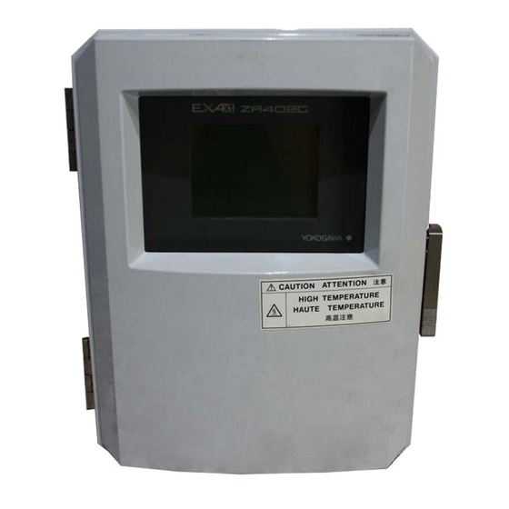
YOKOGAWA EXAxtZR Instruction Manual (207 pages)
Separate type Zirconia Oxygen Analyzer
Brand:
YOKOGAWA
| Category:
Analytical Instruments
| Size: 2 MB
Table of Contents
Table of Contents
8
1 Overview
13
Exaxtzr > System Configuration
13
System 1
13
System 2
14
System 3
15
Exaxtzr > System Components
16
System Components
16
Detectors and Accessories
16
2 Specifications
17
General Specifications
17
Standard Specifications
17
General-Use Separate-Type Detector and Related Equipment
19
ZR22G General-Use Separate-Type Detector
19
ZO21R-L Probe Protector
24
High-Temperature Separate-Type Detector and Related Equipment
25
ZR22G (0.15M) High-Temperature Separate-Type Detector
25
ZO21P-H Adapter for High-Temperature Probe
26
ZR402G Separate-Type Converter
28
Standard Specification
28
Functions
29
ZA8F Flow Setting Unit and ZR40H Automatic Calibration Unit
33
ZA8F Flow Setting Unit
33
ZR40H Automatic Calibration Unit
35
ZO21S Standard Gas Unit
38
Other Equipment
40
Dust Filter for the Detector (Part No.: K9471UA)
40
Auxiliary Ejector for High Temperature (Part No. E7046EC or E7046EN)
41
Stop Valve (Part No. L9852CB or G7016XH)
43
Check Valve (Part No. K9292DN or K9292DS)
44
Air Set (Part No. G7011XF or E7040EL)
45
Zero Gas Cylinder (Part No. G7001ZC)
45
Cylinder Regulator Valve (Part No. G7013XF or G7014XF)
46
Calibration Gas Unit Case (Part No. E7044KF)
46
Model ZR22A Heater Assembly
47
3 Installation
49
Installation of the Detector
49
Location
49
Probe Insertion Hole
49
Installation of the Detector
50
Installation of the Dust Filter( Part no K9471UA)
51
Installation of the Detector (Model ZR22G-015)
53
Installation Location
53
Usage of the High-Temperature Probe Adapter (Model ZO21P-H)
53
Probe Insertion Hole
55
Mounting of the High-Temperature Detector
55
Installation of the Converter
57
Location
57
Mounting of the Converter
57
Installation of ZA8F Flow Setting Unit
60
Location
60
Mounting of ZA8F Flow Setting Unit
60
Installation of ZR40H Automatic Calibration Unit
62
Location
62
Mounting of ZR40H Automatic Calibration Unit
62
Installation of the Calibration Gas Unit Case (E7044KF)
64
Location
64
Mounting
64
Insulation Resistance Test
65
External Dimensions of Detectors with Pressure Compensation
66
4 Piping
73
Piping for System 1
73
Parts Required for Piping in System 1
74
Connection to the Calibration Gas Inlet
75
Connection to the Reference Gas Inlet
75
Piping to the High-Temperature Probe Adapter
76
Piping for System 2
78
Piping Parts for System 2
79
Piping for the Calibration Gas
80
Piping for the Reference Gas
80
Piping to the High-Temperature Probe Adapter
80
Piping for System 3
81
Blow Back Piping
82
Piping for the Detector with Pressure Compensation
84
Piping Parts for a System Using Detector with Pressure Compensation4-14
86
Piping for the Calibration Gas
86
Piping for the Reference Gas
86
5 Wiring
87
General
87
Terminals for the External Wiring in the Converter
88
Wiring
89
Mounting of Cable Gland
90
Wiring for Detector Output
91
Cable Specifications
91
Connection to the Detector
92
Connection to the Converter
93
Wiring for Power to Detector Heater
94
Cable Specifications
94
Connection to Detector
94
Connection to Converter
95
Wiring for Analog Output
96
Cable Specifications
96
Wiring Procedure
96
Power and Grounding Wiring
97
Power Wiring
97
Grounding Wiring
97
Contact Output Wiring
98
Cable Specifications
98
Wiring Procedure
98
Wiring for ZR40H Automatic Calibration Unit
99
Cable Specifications
99
Wiring Procedure
100
Contact Input Wiring
101
Cable Specifications
101
Wiring Procedure
101
6 Components
103
ZR22G Detector
103
General-Purpose Detector (Except for Model ZR22G-015)
103
High-Temperature Detector (Model ZR22G-015)
104
ZR402G Converter
105
ZA8F Flow Setting Unit, ZR40H Automatic Calibration Unit
106
7 Startup
107
Checking Piping and Wiring Connections
107
Checking Valve Setup
107
Supplying Power to the Converter
108
Touchpanel Switch Operations
109
Basic Panel and Switch
109
Display Configuration (for Oxygen Analyzer)
110
Display Functions
111
Entering Numeric and Text Data
111
Confirmation of Converter Type Setting
113
Confirmation of Detector Type Setting
114
Selection of Measurement Gas
114
Output Range Setting
114
Minimum Current (4 Ma) and Maximum Current (20 Ma) Settings
114
Setting Display Item
115
Checking Current Loop
117
Checking Contact I/O
118
Checking Contact Output
118
Checking Calibration Contact Output
119
Checking Input Contacts
119
Calibration
120
Calibration Setup
120
Manual Calibration
121
8 Detailed Data Setting
125
Current Output Setting
125
Setting Minimum Current (4 Ma) and Maximum Current (20 Ma)
125
About Input Ranges
125
Entering Output Damping Constants
126
Selection of Output Mode
126
Default Values
127
Output Hold Setting
128
Definition of Equipment Status
128
Preference Order of Output Hold Value
129
Output Hold Setting
130
Default Values
130
Setting Oxygen Concentration Alarms
131
Alarm Values
131
Alarm Output Actions
131
Alarm Setting Procedure
132
Default Values
133
Output Contact Setup
134
Output Contact
134
Setting Procedure
134
Default Values
137
Input Contact Settings
138
Input Contact Functions
138
Setting Procedure
139
Default Values
139
Other Settings
140
Setting the Date-And-Time
140
Setting Periods over Which Average Values Are Calculated and Periods over Which Maximum and Minimum Values Are Monitored
140
Setting Fuels
141
Setting Passwords
146
9 Calibration
147
Calibration Briefs
147
Principle of Measurement
147
Calibration Gas
148
Compensation
149
Characteristic Data from a Sensor Measured During Calibration
150
Calibration Procedures
151
Calibration Setting
151
Default Values
154
Calibration
155
10 Other Functions
157
Display
157
Detailed Display
157
Trend Graph
161
Auto(Matic) Revert Time
163
Entering Tag Name
163
Language Selection
163
Blowback
164
Blowback Setup
164
Operational Data Initialization
167
Reset
170
Handling of the ZO21S Standard Gas Unit
171
Standard Gas Unit Component Identification
171
Installing Gas Cylinders
172
Calibration Gas Flow
172
Methods of Operating Valves in the ZA8F Flow Setting Unit
175
Preparation before Calibration
175
Operating the Span Gas Flow Setting Valve
175
Operating the Zero Gas Flow Setting Valve
176
Operation after Calibration
176
11 Inspection and Maintenance
177
Inspection and Maintenance of the Detector
178
Cleaning the Calibration Gas Tube
178
Replacing the Sensor Assembly
179
Replacement of the Heater Unit
181
Replacement of Filter Assembly
184
Replacement of O-Ring
184
Cleaning the High-Temperature Probe Adapter
184
Inspection and Maintenance of the Converter
185
Replacing Fuses
185
Cleaning
186
Replacing Flowmeter in ZR40H Autocalibration Unit
187
12 Troubleshooting
189
Displays and Measures to Take When Errors Occur
189
What Is an Error
189
Measures to Take When an Error Occurs
190
Displays and Measures to Take When Alarms Are Generated
193
What Is an Alarm
193
Measures Taken When Alarms Are Generated
194
Countermeasures When Measured Value Shows Error
199
Measured Value Higher than True Value
199
Measured Value Lower than True Value
200
Measurements Sometimes Show Abnormal Values
200
Customer Maintenance Parts List
201
Revision Record
207
Advertisement
Advertisement
Related Products
YOKOGAWA EXA DO402G
YOKOGAWA EXAxt ZR Series
Yokogawa Exaxt450
YOKOGAWA EXAxt 450
YOKOGAWA EXA SC202G
YOKOGAWA EXA SC202S
YOKOGAWA Dpharp vigilantplant EJA440A
YOKOGAWA EJX Series
YOKOGAWA DP harp EJ 110 Series
YOKOGAWA DPharp EJA560E
YOKOGAWA Categories
Measuring Instruments
Test Equipment
Transmitter
Controller
Media Converter
More YOKOGAWA Manuals
Login
Sign In
OR
Sign in with Facebook
Sign in with Google
Upload manual
Upload from disk
Upload from URL