
Related Manuals for YOKOGAWA Vigilantplant NFBU200-S Series


Summary of Contents for YOKOGAWA Vigilantplant NFBU200-S Series
- Page 1 User’s Manual ASIU Analyzer Server Interface Unit Software IM 11B06F01-01E IM 11B06F01-01E 4th Edition...
-
Page 2: Introduction
The contents of the package are as follows. Check the contents of your package. • ASIU installation disc • ASIU User’s Manual (this manual) Media No. IM 11B06F01-01E 4th Edition : Nov. 2011 (YK) IM 11B06F01-01E 4th Edition : Nov. 22, 2011-00 All Rights Reserved Copyright © 2006, Yokogawa Electric Corporation... -
Page 3: Safety Precautions
Warning and Disclaimer The product is provided on an “as is” basis. YOKOGAWA shall have neither liability nor respon- sibility to any person or entity with respect to any direct or indirect loss or damage arising from using the product or any defect of the product that YOKOGAWA can not predict in advance. -
Page 4: Documentation Conventions
Documentation Conventions Symbol Marks Throughout this user’s manual, you will find several different types of symbols are used to identify different sections of text. This section describes these icons. NOTE Identifies important information required to understand operations or functions. Identifies additional information. SEE ALSO Identifies a source to be referred to. -
Page 5: Copyright And Trademark Notices
Copyright and Trademark Notices All Rights Reserved The copyrights of the programs and on-line manual contained in the CD-ROM are reserved. The on-line manual is protected by the PDF security from modification, however, it can be output via a printer. Printing out the on-line manual is only allowed for the purpose of using the product. When using the printed information of the on-line manual, check if the version is the most recent one by referring to the CD-ROM’s version. -
Page 6: Table Of Contents
Toc-1 ASIU Analyzer Server Interface Unit Software IM 11B06F01-01E 4th Edition CONTENTS Introduction ......................i Safety Precautions ....................ii Documentation Conventions ................iii Copyright and Trademark Notices ...............iv Outline ....................... 1-1 Configuration .................... 2-1 2.1 Hardware configuration ................... 2-1 2.2 Software configuration ..................2-1 Functions ....................3-1 I/O card ....................... -
Page 7: Outline
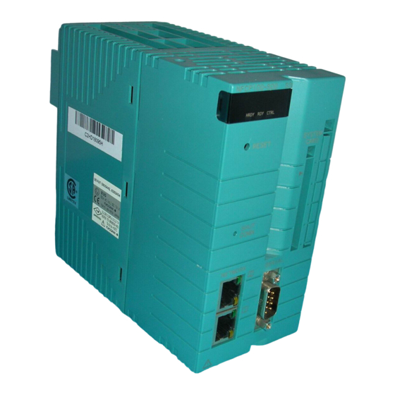
<1. Outline> Outline ASIU is a component designed for Ethernet analyzer bus system. It is realized with the I/O unit software on FCN hardware. ASIU is equipped max. 3 sets of I/O card and transfer I/O information to outside by two type inter- faces: Modbus TCP Ethernet one port and Modbus RTU serial. -
Page 8: Configuration
<2. Configuration> Configuration This chapter explains the configuration of the hardware and software of STARDOM FCN re- quired for ASIU. Refer to the General Specifications of STARDOM for details of each item. 2.1 Hardware configuration The following type FCN is required for the ASIU. l Specification Code Specify these codes when ordering. - Page 9 <2. Configuration> The following software is required as an engineering tool. CD-ROM Code Item Remarks NT203AJ-PC11E Resource configurator It is supplied by CD ROM. Loading a license for installation Modification of IP address IM 11B06F01-01E 4th Edition : Nov. 22, 2011-00...
-
Page 10: Functions
<3. Functions> Functions ASIU has the following functions. 1. Access the I/O cards (DI read, DO write and read back, AI read) 2. Creating the alarm information 3. Interface to DCS through Modbus RTU Slave or Modbus TCP Server I/O card ASIU accesses the I/O card such as DI, DO and AI attached on the FCN to read and write the data periodically. -
Page 11: Alarm Information
100 words Read device ID * 43 (0x2B) ASCII string Device ID consists of vendor, product code and revision number. Vendor : “YOKOGAWA” Product: ”ASIU” REVISION: “1.01.01” (example) l Max number of Client When Modbus TCP Server is used, up to 4 clients (DCS) can be connected at the same time. - Page 12 <3. Functions> Coil (00001 to 09999) Data Address Description DO ON com- 00101 to 00116 A 1 is set when DO001 to DO016 is ON. The coil is back to 0 auto- mand matically after setting a 1. DO OFF com- 00201 to 00216 A 1 is set when DO001 to DO016 is OFF.
-
Page 13: Engineering
<4. Engineering> Engineering ASIU requires the engineering at installation, and modification. The install procedure of FCN is referred to “STARDOM FCN/FCJ Software Installation” (IM 34P02Q91-01E), and “STARDOM FCN/FCJ Guide” (IM 34P02Q01-01E). Installation This section explains the setup of FCN, license registration, loading of the application software, initializing of IP address and assignment of I/O cards. 4.1.1 Preparation Installation of the engineering tool... - Page 14 <4. Engineering> Setting the system card Set the system compact flash card for FCN to PC by USB adaptor. Run the following batch file. [Uncompressed folder]/INSTALL_ASIU/install_ASIU.bat This batch file sets the ASIU application and system setting file on the system card. System setting file includes initial IP address setting.
-
Page 15: Modification Work
<4. Engineering> 4.2 Modification work There are 2 modification works at site. One is to change of IP address and the other is to change an assignment of I/O terminal. Here explains how to change the assignment of I/O terminal. This work requires the resource configurator. -
Page 16: Supplement
(3) FCN starts on IP address setting mode. Method of use web browser on PC. (1) Access to the URL URL = http://FCJ’s IP address/MNT User Account = “stardom” Password = “YOKOGAWA” IM 11B06F01-01E 4th Edition : Nov. 22, 2011-00... - Page 17 <4. Engineering> (2) Click the Maintenance Menu (3) Click the Reboot IM 11B06F01-01E 4th Edition : Nov. 22, 2011-00...
- Page 18 <4. Engineering> (4) Select the Reboot (IP Address Setting Mode) and press “OK” FCN restarts on IP address setting mode. IM 11B06F01-01E 4th Edition : Nov. 22, 2011-00...
- Page 19 <4. Engineering> Setting IP address Start the resource configurator software on PC and wait for a message “A new controller is con- nected”. When the message appears, select the “Setting IP Address” on “File” menu. IP address, Subnet mask, Gateway and Time zone parameters are set on this dialogue window. Reboot the FCN after the setting.
-
Page 20: Modification Of Serial Port Setting
<4. Engineering> 4.3.2 Modification of serial port setting In the case of using the Modbus RTU as external interface of ASIU, this operation is required. ASIU has two communication ports and all initial setting data are as follows. Baudrate =9600 DataBitLength StopBitLength Parity =NONE After FCN mode is changed to maintenance mode, the communication port is set with the main- tenance window on web browser. -
Page 21: Opc Da 2.0 Interface
<5. OPC DA 2.0 Interface> OPC DA 2.0 Interface This chapter explains the OPC DA 2.0 interface of ASGW and ASIU. Adding an OPC server of STARDOM to the system allows ASGW/ASIU to have the OPC in- terface. There is no need to add any special settings to the ASGW/ASIU application. Map- ping Modbus data of ASIU to ASGW allows ASIU data to be read and written by accessing ASGW through the OPC interface. -
Page 22: List Of Opc Data Names
<5. OPC DA 2.0 Interface> List of OPC Data Names The table below shows a list of ASGW/ASIU’s data names that can be accessed via STARDOM OPC DA2.0 server. Data names are common to ASGW and ASIU. ASGW/ASIU’s node name designated in the setting file on the STARDOM OPC server is as- signed to “Node.”... - Page 23 <5. OPC DA 2.0 Interface> IREG (30001 to 39000) Read only. Writing through the OPC interface does not cause an error, but nothing can be written onto the Modbus area of ASGW/ASIU. Unmapped address data is always read as “0”. OPC Data Name OPC Data Type Function...
-
Page 24: Revision Information
Revision Information Title : ASIU Analyzer Sever Interface Unit Software Manual No. : IM 11B06F01-01E Oct. 2006/1st Edition Newly published Jan. 2010/2nd Edition P.3-3 Addition of Input register. Jun. 2011/3rd Edition Addition of chapter 5. Nov. 2011/4th Edition Revised for “GC8000”. IM 11B06F01-01E 4th Edition : Nov.
Need help?
Do you have a question about the Vigilantplant NFBU200-S Series and is the answer not in the manual?
Questions and answers