YOKOGAWA ZR22G User Manual
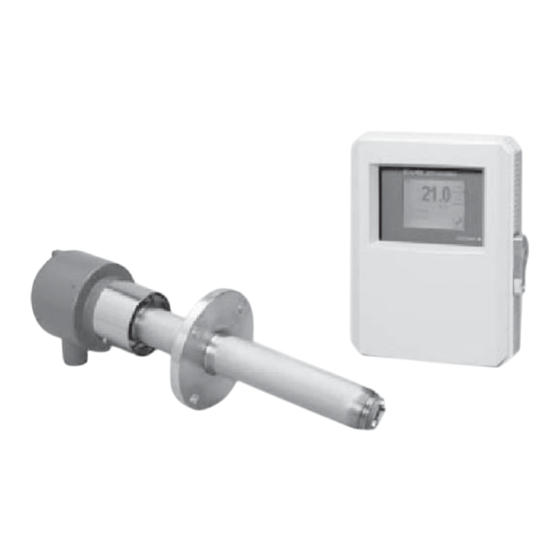
Separate type zirconia
oxygen/humidity analyzer
Hide thumbs
Also See for ZR22G:
- User manual (241 pages) ,
- Technical information (37 pages) ,
- General specifications (37 pages)
Table of Contents
Advertisement
Quick Links
Download this manual
See also:
Technical Information
Advertisement
Table of Contents

Related Manuals for YOKOGAWA ZR22G


Summary of Contents for YOKOGAWA ZR22G
- Page 1 User’s Manual Model ZR22G, ZR402G Separate type Zirconia Oxygen/Humidity Analyzer IM 11M12A01-02E IM 11M12A01-02E 16th Edition...
- Page 1 User’s Manual Model ZR22G, ZR402G Separate type Zirconia Oxygen/Humidity Analyzer IM 11M12A01-02E IM 11M12A01-02E 13th Edition...
- Page 2 High Temperature Humidity Analyzer when the option code “/HS (Set for Humidity Analyzer)” of ZR402G is selected. After that, in this manaul, the Humidity Analyzer refers to the thing which ZR22G combined with ZR402G with “/HS”. In addition, in this manual, the Oxygen Analyzer is mainly listed. When there are not mentions such as “in the case of Humidity Analyzer”, it becomes same as the Oxygen Analyzer.
- Page 2 High Temperature Humidity Analyzer when the option code “/HS (Set for Humidity Analyzer)” of ZR402G is selected. After that, in this manaul, the Humidity Analyzer refers to the thing which ZR22G combined with ZR402G with “/HS”. In addition, in this manual, the Oxygen Analyzer is mainly listed. When there are not mentions such as “in the case of Humidity Analyzer”, it becomes same as the Oxygen Analyzer.
- Page 3 Models and descriptions in this manual are listed below. Models and descriptions in this manual Description in this manual Model Product Name Specification Installation Operation Maintenance CMPL ZR22G General use detector ○ ○ ○ ○ ○ ZR22G High temperature detector (0.15m) ○...
- Page 3 Models and descriptions in this manual are listed below. Models and descriptions in this manual Description in this manual Model Product Name Specification Installation Operation Maintenance CMPL ZR22G General use detector ○ ○ ○ ○ ○ ZR22G High temperature detector (0.15m) ○...
- Page 4 For the safe use of this equipment WARNING Handle it with care. Be sure not to accidentally drop it. Handle safely to avoid injury. Connect the power supply cord only after confirming that the supply voltage matches the rating of this equipment.
- Page 4 For the safe use of this equipment WARNING Handle it with care. Be sure not to accidentally drop it. Handle safely to avoid injury. Connect the power supply cord only after confirming that the supply voltage matches the rating of this equipment.
-
Page 5: Safety Precautions
The product is provided on an “as is” basis. YOKOGAWA shall have neither liability nor responsibility to any person or entity with respect to any direct or indirect loss or damage arising from using the product or any defect of the product that YOKOGAWA can not predict in advance. IM 11M12A01-02E... -
Page 5: Safety Precautions
The product is provided on an “as is” basis. YOKOGAWA shall have neither liability nor responsibility to any person or entity with respect to any direct or indirect loss or damage arising from using the product or any defect of the product that YOKOGAWA can not predict in advance. IM 11M12A01-02E... - Page 6 • No part of the user’s manuals may be transferred or reproduced without prior written consent from YOKOGAWA. • YOKOGAWA reserves the right to make improvements in the user’s manuals and product at any time, without notice or obligation. • If you have any questions, or you find mistakes or omissions in the user’s manuals, please contact our sales representative or your local distributor.
- Page 6 • No part of the user’s manuals may be transferred or reproduced without prior written consent from YOKOGAWA. • YOKOGAWA reserves the right to make improvements in the user’s manuals and product at any time, without notice or obligation. • If you have any questions, or you find mistakes or omissions in the user’s manuals, please contact our sales representative or your local distributor.
- Page 7 Batteries are included in this product. Batteries incorporated into this product cannot be removed by yourself. Dispose them together with this product. When you dispose this product in the EU, contact your local Yokogawa Europe B.V.office. Do not dispose them as domestic household waste.
- Page 7 Batteries are included in this product. Batteries incorporated into this product cannot be removed by yourself. Dispose them together with this product. When you dispose this product in the EU, contact your local Yokogawa Europe B.V.office. Do not dispose them as domestic household waste.
-
Page 8: Table Of Contents
ZH21B Dust Protector ................ 2-9 Separate type Detector for High Temperature and Related Equipment ... 2-10 2.3.1 ZR22G (0.15m) Separate type Detector for High Temperature ..2-10 2.3.2 ZO21P High Temperature Probe Adapter ........2-11 ZR402G Separate type Converter ..............2-13 ZA8F Flow Setting Unit and ZR40H Automatic Calibration Unit .............. -
Page 8: Table Of Contents
ZH21B Dust Protector ................ 2-8 Separate type Detector for High Temperature and Related Equipment ..2-9 2.3.1 ZR22G (0.15m) Separate type Detector for High Temperature ..2-9 2.3.2 ZO21P High Temperature Probe Adapter ........2-10 ZR402G Separate type Converter ..............2-11 ZA8F Flow Setting Unit and ZR40H Automatic Calibration Unit .............. - Page 9 Installation of the Dust Filter (K9471UA), Dust Guard Protector (K9471UC), Probe Protector ZO21R ..........3-2 3.1.4 Installation of ZH21B Dust Protector ..........3-4 Installation of High Temperature Detector (ZR22G-015) ....................... 3-5 3.2.1 Usage of the High Temperature Probe Adapter (ZO21P-H) ....3-5 3.2.2 Probe Insertion Hole ................3-6 3.2.3...
- Page 9 Installation of the Dust Filter (K9471UA), Dust Guard Protector (K9471UC), Probe Protector ZO21R ..........3-2 3.1.4 Installation of ZH21B Dust Protector ..........3-4 Installation of High Temperature Detector (ZR22G-015) ....................... 3-5 3.2.1 Usage of the High Temperature Probe Adapter (ZO21P-H) ....3-5 3.2.2 Probe Insertion Hole ................3-6 3.2.3...
- Page 10 Wiring for ZR40H Automatic Calibration Unit ........5-11 5.2.10 Temperature Input Wiring ..............5-12 Components ..................... 6-1 ZR22G Detector ....................6-1 6.1.1 General-purpose Detector (except for ZR22G-015)......6-1 6.1.2 High Temperature Detector (ZR22G-015) ......... 6-2 ZR402G Converter .................... 6-3 Touchpanel Switch Operations ............... 6-4 6.3.1 Basic Panel and Switch ..............
- Page 10 Wiring for ZR40H Automatic Calibration Unit ........5-11 5.2.10 Temperature Input Wiring ..............5-12 Components ..................... 6-1 ZR22G Detector ....................6-1 6.1.1 General-purpose Detector (except for ZR22G-015)......6-1 6.1.2 High Temperature Detector (ZR22G-015) ......... 6-2 ZR402G Converter .................... 6-3 Touchpanel Switch Operations ............... 6-4 6.3.1 Basic Panel and Switch ..............
- Page 11 Toc-4 7.12 Calibration ....................... 7-12 7.12.1 Calibration Setup ................7-12 7.12.2 Manual Calibration ................7-13 Detailed Data Setting ................8-1 Current Output Setting ..................8-1 8.1.1 Oxygen Analyzer - Setting Minimum Current (4 mA) and Maximum Current (20 mA) ................. 8-1 8.1.2 Humidity Analyzer - Setting Minimum Current (4 mA) and Maximum Current (20 mA) .................
- Page 11 Toc-4 7.12 Calibration ....................... 7-12 7.12.1 Calibration Setup ................7-12 7.12.2 Manual Calibration ................7-13 Detailed Data Setting ................8-1 Current Output Setting ..................8-1 8.1.1 Oxygen Analyzer - Setting Minimum Current (4 mA) and Maximum Current (20 mA) ................. 8-1 8.1.2 Humidity Analyzer - Setting Minimum Current (4 mA) and Maximum Current (20 mA) .................
- Page 12 Toc-5 9.1.3 Calibration Gas .................. 9-4 9.1.4 Compensation ..................9-4 9.1.5 Characteristic Data from a Sensor Measured During Calibration ..9-5 Calibration Procedures ..................9-6 9.2.1 Mode ....................9-6 9.2.2 Calibration Procedure ................ 9-7 9.2.3 Zero gas Concentration ..............9-7 9.2.4 Span gas Concentration ..............
- Page 12 Toc-5 9.1.3 Calibration Gas .................. 9-4 9.1.4 Compensation ..................9-4 9.1.5 Characteristic Data from a Sensor Measured During Calibration ..9-5 Calibration Procedures ..................9-6 9.2.1 Mode ....................9-6 9.2.2 Calibration Procedure ................ 9-7 9.2.3 Zero gas Concentration ..............9-7 9.2.4 Span gas Concentration ..............
- Page 13 Toc-6 10.4 Blow Back ......................10-8 10.4.1 Mode ....................10-8 10.4.2 Operation of Blow back ..............10-8 10.4.3 Setting Output Hold Time and Blow back Time ....... 10-9 10.4.4 Setting Interval, Start Date, and Start Time ........10-9 10.4.5 Default Setting................10-10 10.5 Parameter Initialization .................10-10 10.6...
- Page 13 Toc-6 10.4 Blow Back ......................10-8 10.4.1 Mode ....................10-8 10.4.2 Operation of Blow back ..............10-8 10.4.3 Setting Output Hold Time and Blow back Time ....... 10-9 10.4.4 Setting Interval, Start Date, and Start Time ........10-9 10.4.5 Default Setting................10-10 10.5 Parameter Initialization .................10-10 10.6...
-
Page 14: Im 11M12A01-02E 13Th Edition : Jul. 19,
Toc-7 Customer Maintenance Parts List ........CMPL 11M12A01-02E Customer Maintenance Parts List ........CMPL 11M12C01-01E Customer Maintenance Parts List ........CMPL 11M03B01-10E Customer Maintenance Parts List ........CMPL 11M03B01-05E Customer Maintenance Parts List ........CMPL 11M12A01-11E Customer Maintenance Parts List ..........CMPL 11M3D1-01E Revision Information ....................i IM 11M12A01-02E 16th Edition : Mar. -
Page 14: Im 11M12A01-02E 13Th Edition : Jul. 19,
Toc-7 Customer Maintenance Parts List ........CMPL 11M12A01-02E Customer Maintenance Parts List ........CMPL 11M12C01-01E Customer Maintenance Parts List ........CMPL 11M03B01-10E Customer Maintenance Parts List ........CMPL 11M03B01-05E Customer Maintenance Parts List ........CMPL 11M12A01-11E Customer Maintenance Parts List ..........CMPL 11M3D1-01E Revision Information ....................i IM 11M12A01-02E 13th Edition : Jul. - Page 15 Blank Page...
- Page 15 Blank Page...
-
Page 16: Overview
CO , SOx and NOx. The ZR22G Separate type Detector uses a high-reliability Zirconia sensor, and its heater assembly can be replaced on site. The detector is mounted, for example, on the wall of a flue and can measure the gases directly. -
Page 16: Overview
CO , SOx and NOx. The ZR22G Separate type Detector uses a high-reliability Zirconia sensor, and its heater assembly can be replaced on site. The detector is mounted, for example, on the wall of a flue and can measure the gases directly. -
Page 17: System 2
<1. Overview> ZR402G Converter ZR22G Separate type Zirconia Oxygen/Humidity Analyzer, Detector EXA ZR402G Signal Stop valve (6-core shield cable) 100 to 240 V AC Heater(2-core) Contact input Analog output, contact output (Digital output HART) Calibration gas ZO21S Standard gas unit F1-1E.ai... -
Page 18: System 3
<1. Overview> ZR402G Converter ZR22G Separate type Zirconia Oxygen/Humidity Analyzer, Detector EXA ZR402G Signal Check valve (6-core shield cable) 100 to or Stop Valve 240 V AC Heater(2-core) Contact input Analog output, contact output (Digital output HART) Needle Flowmeter Reference... -
Page 19: Exaxt Zr > System Components
G7013XF, G7014XF Pressure Reducing Valve for Gas Cylinder E7044KF Case Assembly for Calibration gas Cylinder Model ZR22A Heater Assembly (Spare Parts for Model ZR22G) A: Items required for the above system example B: To be selected depending on each application. For details, refer to corresponding chapter. -
Page 20: Specifications
Oxygen concentration in combustion exhaust gas and mixed gas (excluding inflammable gases, may not be applicable corrosive gas such as ammonia, chlorine is present-check with YOKOGAWA) The sampling gases containing a corrosive gas such as ammonia or chlorine may be applicable to our oxygen gas analyzer. In this case, contact with YOKOGAWA and its agency. -
Page 20: Specifications
Oxygen concentration in combustion exhaust gas and mixed gas (excluding inflammable gases, may not be applicable corrosive gas such as ammonia, chlorine is present-check with YOKOGAWA) The sampling gases containing a corrosive gas such as ammonia or chlorine may be applicable to our oxygen gas analyzer. In this case, contact with YOKOGAWA and its agency. - Page 21 Response of 90% within 5 seconds. (Measured after gas is introduced from calibration gas inlet and analog output start changing.) Safety, EMC and RoHS conforming standards the ZR22G and ZR402G Installation altitude based on IEC 61010: 2000 m or less...
- Page 21 Response of 90% within 5 seconds. (Measured after gas is introduced from calibration gas inlet and analog output start changing.) Safety, EMC and RoHS conforming standards the ZR22G and ZR402G Installation altitude based on IEC 61010: 2000 m or less...
-
Page 22: General Use Separate Type Detector And Related Equipment
General use Separate type Detector and Related Equipment General use separate type detector ZR22G can be used in combination with the probe protector ZO21R (see Section 2.2.2). In case of Humidity Analyzer, the “Detector with dust protector” consists of ZR22G general-use separate-type detector and ZH21B dust protector (refer to Section 2.2.3). -
Page 22: General Use Separate Type Detector And Related Equipment
General use Separate type Detector and Related Equipment General use separate type detector ZR22G can be used in combination with the probe protector ZO21R (see Section 2.2.2). In case of Humidity Analyzer, the “Detector with dust protector” consists of ZR22G general-use separate-type detector and ZH21B dust protector (refer to Section 2.2.3). - Page 23 <2. Specifications> Probe Mounting Angle: Horizontal to vertically downward. When the probe insertion length is 2 m or less, installing at angles from horizontal to vertically downward is available. When the probe insertion length is exceeds 2.5 m, mount vertically downward (within ±5°), and use a probe protector. Weight: Insertion length of 0.4 m: approx.
- Page 23 <2. Specifications> Probe Mounting Angle: Horizontal to vertically downward. When the probe insertion length is 2 m or less, installing at angles from horizontal to vertically downward is available. When the probe insertion length is exceeds 2.5 m, mount vertically downward (within ±5°), and use a probe protector. Weight: Insertion length of 0.4 m: approx.
- Page 24 Option code Description ZR22G - - - - - - - - - - - - - - - - - - - - - - - - - - - - - - - - - - - - - - - - - - - -...
- Page 24 Option code Description ZR22G - - - - - - - - - - - - - - - - - - - - - - - - - - - - - - - - - - - - - - - - - - - -...
- Page 25 <2. Specifications> EXTERNAL DIMENSIONS 1. Model ZR22G Separate type Zirconia Oxygen/Humidity Analyzer, Detectors 283 to 292 Unit : mm L=0.15, 0.4, 0.7, 1.0, Rc1/4 or 1/4NPT 1.5, 2.0, 2.5, 3.0 Reference gas inlet 3.6, 4.2, 4.8, 5.4 (m) 155 to 163 2-G1/2,2-1/2NPT etc.
- Page 25 <2. Specifications> EXTERNAL DIMENSIONS 1. Model ZR22G Separate type Zirconia Oxygen/Humidity Analyzer, Detectors 283 to 292 Unit : mm L=0.15, 0.4, 0.7, 1.0, Rc1/4 or 1/4NPT 1.5, 2.0, 2.5, 3.0 Reference gas inlet 3.6, 4.2, 4.8, 5.4 (m) 155 to 163 2-G1/2,2-1/2NPT etc.
-
Page 26: Zo21R Probe Protector
<2. Specifications> 2. Model ZR22G...-P (with pressure compensation) Separate type Zirconia Oxygen Analyzer, Detectors L=0.15, 0.4, 0.7, 1.0, 1.5, 2.0, 2.5, 3.0 Rc1/4 or 1/4NPT 3.6, 4.2, 4.8, 5.4 (m) Reference gas inlet 2-G1/2, 2-1/2NPT etc. Cable connection port Reference gas outlet... -
Page 27: Zh21B Dust Protector
<2. Specifications> 2.2.2 ZO21R Probe Protector Used when sample gas flow velocity is approx. 10 m/sec or more and dust particles wears the detector in cases such as pulverized coal boiler of fluidized bed furnace (or burner) to protect the detector from wearing by dust particles. When probe insertion length is 2.5 m or more and □... -
Page 27: Zh21B Dust Protector
- - - - - - ANSI Class 150 4B FF (*2) Style code - - - - - - Style B Note: The flange thickness varies. Specify the probe ZR22G-040-□-K Specify the probe ZR22G-040-□-C IM 11M12A01-02E 13th Edition : Jul. 19, 2017-00... -
Page 28: Separate Type Detector For High Temperature And Related Equipment
- - - - - - ANSI Class 150 4B FF (*2) Style code - - - - - - Style B Note: The flange thickness varies. Specify the probe ZR22G-040-□-K Specify the probe ZR22G-040-□-C Unit: mm 428 (Insertion length) JIS flange Install facing upwards ANSI flange ZH21B.ai... -
Page 28: Separate Type Detector For High Temperature And Related Equipment
4 - Ø19 ANSI Class 150 4B FF 228.6 190.5 8 - Ø19 Separate type Detector for High Temperature and Related Equipment 2.3.1 ZR22G (0.15m) Separate type Detector for High Temperature Standard Specifications Construction: Water-resistant, non-explosionproof Probe length: 0.15 m Terminal box:... -
Page 29: Zo21P High Temperature Probe Adapter
2-10 <2. Specifications> Separate type Detector for High Temperature and Related Equipment 2.3.1 ZR22G (0.15m) Separate type Detector for High Temperature Standard Specifications Construction: Water-resistant, non-explosionproof Probe length: 0.15 m Terminal box: Aluminum alloy Probe material: Probe material in contact with gas: SUS 316 (JIS) (Probe), SUS304 (JIS) -
Page 29: Zo21P High Temperature Probe Adapter
/EJ2 Ejector Assy with E7046EN Tag plate /SCT Stainless steel tag plate Note: For this high-temperature use probe adapter, be sure to specify the ZR22G probe of its insertion length 0.15 meters. IM 11M12A01-02E 13th Edition : Jul. 19, 2017-00... -
Page 30: Zr402G Separate Type Converter
/EJ2 Ejector Assy with E7046EN Tag plate /SCT Stainless steel tag plate Note: For this high-temperature use probe adapter, be sure to specify the ZR22G probe of its insertion length 0.15 meters. IM 11M12A01-02E 16th Edition : Mar. 19, 2020-00... -
Page 30: Zr402G Separate Type Converter
Sample gas outlet Flange (Thickness 5) JIS 5K 32 FF equivalent Rc1/2(Note2) Gasket (Thickness 1.5) Ø60.5 ØA Flange <1> Detector(ZR22G) Flange provided Approx. 48 by customer Ø52 over Reference gas inlet Rc1/4 or 1/4NPT High temperature Probe SiC pipe Ø30... - Page 31 Sample gas outlet Flange (Thickness 5) JIS 5K 32 FF equivalent Rc1/2(Note2) Gasket (Thickness 1.5) Ø60.5 ØA Flange <1> Detector(ZR22G) Flange provided Approx. 48 by customer Ø52 over Reference gas inlet Rc1/4 or 1/4NPT High temperature Probe SiC pipe Ø30...
- Page 31 2-12 <2. Specifications> Contact Input: Two points Analog Input: One point (thermal input 4-20 mA) Automatic Calibration Output: Two points (for dedicated automatic calibration unit) Ambient Temperature: -20 to 55°C Storage Temperature: -30 to 70°C Ambient Humidity: 0 to 95%RH (Non-condensing) Power Supply Voltage: Ratings;...
- Page 32 2-13 <2. Specifications> ZR402G Separate type Converter Standard Specification The ZR402G Separate type Converter can be controlled by LCD touchscreen on the converter. Display: LCD display of size 320 by 240 dot with touchscreen. Output Signal: 4 to 20 mA DC, two points (maximum load resistance 550 Ω) Contact Output Signal: Four points (one is fail-safe, normally open) Contact Input: Two points...
- Page 32 2-13 <2. Specifications> Maintenance Functions: Can operate updated data settings in daily operation and checking. Display data settings, calibration data settings, blow back data settings, current output loop check, input/output contact check. Setup Functions: Initial settings suit for the plant conditions when installing the converter. Equipment settings, current output data settings, alarm data settings, contact data settings, other settings.
- Page 33 2-14 <2. Specifications> Semi-auto Calibration; Requires the ZR40H Automatic Calibration Unit. Input calibration direction on the touchscreen or contact, then it calibrates automatically afterwards. Manual Calibration; Calibration with opening/closing the valve of calibration gas in operation interactively with an LCD touchscreen. Blow back Function: Output through the contact in the set period and time.
- Page 33 2-14 <2. Specifications> Oxygen analyzer; Range: Any setting between 0 to 5 through 0 to 100 vol%O 1 vol%O , or partial range is available (Maximum range value/ minimum range value 1.3 or more). For the log output, the minimum range value is fixed at 0.1 vol%O 4 to 20 mA DC linear or log can be selected.
- Page 34 2-15 <2. Specifications> Contact Related Items: Selection of contact input 1 and 2, selection of contact output 1 to 4 (abnormal, high-high alarm, high alarm, low alarm, low-low alarm, maintenance, calibrating, range switching, warming-up, calibration gas pressure decrease, temperature high alarm, blow back, flameout gas detection, calibration coefficient alarm, stabilization timeout) Converter Output: Two points mA analog output (4 to 20 mA DC (maximum load resistance...
- Page 34 2-15 <2. Specifications> Model and Codes Option Model Suffix code Description code ZR402G - - - - - - - - - - - - - - - - - - - - - - Separate type Zirconia Oxygen/Humidity Analyzer, Converter Converter - - - - - - G1/2...
- Page 35 2-16 <2. Specifications> Span calibration gas concentration setting range: 4.5 to 100 vol%O (in increments of 0.01 vol%O in smallest units). Use nitrogen-balanced mixed gas containing 0 to 10 vol%O scale of oxygen, and 80 to 100 vol%O scale of oxygen for standard zero gas and standard span gas respectively.
- Page 35 2-16 <2. Specifications> External Dimensions Unit: mm 1 to 6 (Panel Thickness) 2B mounting pipe 4 - Ø6 holes EXA ZR402G for Wall mounting 57.3 136.3 54.7 8-G1/2, *8-1/2NPT etc (Wiring connection) *: 1/2NPT with plug 24 14 ( for wall mounting) 4 - Ø6 holes 4-R8 to R10 4-C5 to C8...
-
Page 36: Za8F Flow Setting Unit And Zr40H Automatic Calibration Unit
2-17 <2. Specifications> External Dimensions Unit: mm 1 to 6 (Panel Thickness) 2B mounting pipe 4 - Ø6 holes EXA ZR402G for Wall mounting 57.3 136.3 54.7 8-G1/2, *8-1/2NPT etc (Wiring connection) *: 1/2NPT with plug 24 14 ( for wall mounting) 4 - Ø6 holes 4-R8 to R10 4-C5 to C8... -
Page 36: Za8F Flow Setting Unit And Zr40H Automatic Calibration Unit
Weight: Approx. 2.3 kg Calibration gas (zero gas, span gas) Consumption: Approx. 0.7 l/min (at calibration time only) NOTE Use instrument air for span calibration gas, if no instrument air is available, contact YOKOGAWA. Model and Codes Model Suffix code... - Page 37 Weight: Approx. 2.3 kg Calibration gas (zero gas, span gas) Consumption: Approx. 0.7 l/min (at calibration time only) NOTE Use instrument air for span calibration gas, if no instrument air is available, contact YOKOGAWA. Model and Codes Model Suffix code...
- Page 37 2-18 <2. Specifications> External Dimensions Unit : mm ø6 Hole REFERENCE CHECK REFERENCE SPAN ZERO 2B mounting pipe 235.8 222.8 Calibration gas outlet Span gas inlet Reference gas outlet Zero gas inlet Piping connection port A Model Piping connection port A ZA8F-J*C 5 - Rc1/4 ZA8F-A*C...
- Page 38 2-19 <2. Specifications> External Dimensions Unit : mm ø6 Hole REFERENCE CHECK REFERENCE SPAN ZERO 2B mounting pipe 235.8 222.8 Calibration gas outlet Span gas inlet Reference gas outlet Zero gas inlet Piping connection port A Model Piping connection port A ZA8F-J*C 5 - Rc1/4 ZA8F-A*C...
- Page 38 2-19 <2. Specifications> 2.5.2 ZR40H Automatic Calibration Unit This automatic calibration unit is applied to supply specified flow of reference gas and calibration gas during automatic calibration to the detector in a system configuration (System 3). Specifications Used when auto calibration is required for the separate type and instrument air is provided. The solenoid valves are provided as standard.
- Page 39 2-20 <2. Specifications> 2.5.2 ZR40H Automatic Calibration Unit This automatic calibration unit is applied to supply specified flow of reference gas and calibration gas during automatic calibration to the detector in a system configuration (System 3). Specifications Used when auto calibration is required for the separate type and instrument air is provided. The solenoid valves are provided as standard.
- Page 39 2-20 <2. Specifications> External Dimensions Unit: mm 2B pipe mounting example Wiring inlet ; 2-G1/2,Pg13.5,M20X1.5 or 1/2NPT(Female) (wiring inlet is at same position on rear) *1 with four ISO M6 screws can wall-mount 116.5 71.5 41.2 41.2 4 - Ø6.5 Connection port Flowmeter Needle valve Terminal box...
-
Page 40: Zo21S Standard Gas Unit
2-21 <2. Specifications> External Dimensions Unit: mm 2B pipe mounting example Wiring inlet ; 2-G1/2,Pg13.5,M20X1.5 or 1/2NPT(Female) (wiring inlet is at same position on rear) *1 with four ISO M6 screws can wall-mount 116.5 71.5 41.2 41.2 4 - Ø6.5 Connection port Flowmeter Needle valve Terminal box... -
Page 40: Zo21S Standard Gas Unit
2-21 <2. Specifications> Piping Diagram CHECK ZR40H Automatic ZR402G Converter Calibration Unit AC-Z Zero Flowmeter Flowmeter AC-S Solenoid valve EV1,2 AC-C Span F35_00.ai AIR IN ZERO GAS IN Instrument air Approx. 1.5 l/min Needle valve is supplied as on accessory with flowmeter F2-6_3E.ai ZO21S Standard Gas Unit This is a handy unit to supply zero gas and span gas to the detector in a system configuration... -
Page 41: Other Equipments
2-22 <2. Specifications> Piping Diagram CHECK ZR40H Automatic ZR402G Converter Calibration Unit AC-Z Zero Flowmeter Flowmeter AC-S Solenoid valve EV1,2 AC-C Span F35_00.ai AIR IN ZERO GAS IN Instrument air Approx. 1.5 l/min Needle valve is supplied as on accessory with flowmeter F2-6_3E.ai ZO21S Standard Gas Unit This is a handy unit to supply zero gas and span gas to the detector in a system configuration... -
Page 41: Other Equipments
2-22 <2. Specifications> External Dimensions Unit: mm Flow checker Span gas valve Zero gas valve Gas outlet Zero gas cylinder (6 cylinder): E7050BA F2-7E.ai Other Equipments 2.7.1 Dust Filter for the Detector (K9471UA) This filter is used to protect the detector sensor from a corrosive dust components or high velocity dust in recovery boilers and cement kilns. -
Page 42: Dust Guard Protector (K9471Uc)
2-23 <2. Specifications> External Dimensions Unit: mm Flow checker Span gas valve Zero gas valve Gas outlet Zero gas cylinder (6 cylinder): E7050BA F2-7E.ai Other Equipments 2.7.1 Dust Filter for the Detector (K9471UA) This filter is used to protect the detector sensor from a corrosive dust components or high velocity dust in recovery boilers and cement kilns. -
Page 42: Dust Guard Protector (K9471Uc)
2-23 <2. Specifications> 2.7.2 Dust Guard Protector (K9471UC) Recommended to be used when sample gas is likely to flow directly into the cell due to its flow direction in the stack or the like, flammable dust may go into the cell, or water drops are likely to fall and remain in the cell during downtime or the like due to the installation position. - Page 43 2-24 <2. Specifications> 2.7.2 Dust Guard Protector (K9471UC) Recommended to be used when sample gas is likely to flow directly into the cell due to its flow direction in the stack or the like, flammable dust may go into the cell, or water drops are likely to fall and remain in the cell during downtime or the like due to the installation position.
- Page 43 2-24 <2. Specifications> < Pressure setting for the ejector assembly for high temperature use > Pressure supply for the ejector assembly should be set so that the suction flow of the sample gas becomes approximately 5 l/min. To set this, proceed as follows: (1) In Graph 4, draw a horizontal line from the 5 l/min point.
-
Page 44: Stop Valve (L9852Cb, G7016Xh)
2-25 <2. Specifications> < Pressure setting for the ejector assembly for high temperature use > Pressure supply for the ejector assembly should be set so that the suction flow of the sample gas becomes approximately 5 l/min. To set this, proceed as follows: (1) In Graph 4, draw a horizontal line from the 5 l/min point. -
Page 44: Stop Valve (L9852Cb, G7016Xh)
2-25 <2. Specifications> Pressure gauge assembly Pressure gauge Ejector Needle valve <2> Nozzle (Note1) Ø43 Detector R1/2 <3> Instrument air inlet <1> Blow Rc1/4 (Note1) The connecter of ejector assembly is a <1> Rc1/4 or 1/4 FNPT dedicated connecter with nozzle function. <2>... -
Page 45: Check Valve (K9292Dn, K9292Ds)
2-26 <2. Specifications> Pressure gauge assembly Pressure gauge Ejector Needle valve <2> Nozzle (Note1) Ø43 Detector R1/2 <3> Instrument air inlet <1> Blow Rc1/4 (Note1) The connecter of ejector assembly is a <1> Rc1/4 or 1/4 FNPT dedicated connecter with nozzle function. <2>... -
Page 45: Check Valve (K9292Dn, K9292Ds)
2-26 <2. Specifications> Part No. Description L9852CB Joint: Rc 1/4, Material: SUS316 (JIS) G7016XH Joint: 1/4 NPT, Material: SUS316 (JIS) Unit: mm Ø48 Rc1/4 or 1/4NPT F15.ai 2.7.5 Check Valve (K9292DN, K9292DS) This valve is mounted on the calibration gas line (directly connected to the detector). This is applied to a system based on the (System 2 and 3) system configuration . -
Page 46: Air Set
2-27 <2. Specifications> 2.7.4 Stop Valve (L9852CB, G7016XH) This valve mounted on the calibration gas line in the system to allow for manual calibration. This is applies to the system configuration shown for system 1 in section 1. Standard Specifications Connection: Rc 1/4 or 1/4 NPT(F) Material: SUS 316 (JIS) -
Page 46: Air Set
2-27 <2. Specifications> 2.7.6 Air Set This set is used to lower the pressure when instrument air is used as the reference and span gases. Standard Specifications G7003XF, K9473XK Primary Pressure: Max. 1 MPa G Secondary Pressure: 0.02 to 0.2 MPa G Connection: Rc1/4 or 1/4NPT(F) with joint adapter Weight:... -
Page 47: Zero Gas Cylinder (G7001Zc)
2-28 <2. Specifications> 2.7.6 Air Set This set is used to lower the pressure when instrument air is used as the reference and span gases. Standard Specifications G7003XF, K9473XK Primary Pressure: Max. 1 MPa G Secondary Pressure: 0.02 to 0.2 MPa G Connection: Rc1/4 or 1/4NPT(F) with joint adapter Weight:... -
Page 47: Zero Gas Cylinder (G7001Zc)
2-28 <2. Specifications> 2.7.7 Zero Gas Cylinder (G7001ZC) The gas from this cylinder is used as the calibration zero gas and detector purge gas. Standard Specifications Capacity: 3.4 L Filled pressure: 9.8 to 12 MPa G Composition: 0.95 to 1.0 vol%O in N Weight: Approx. -
Page 48: Case Assembly For Calibration Gas Cylinder (E7044Kf)
2-29 <2. Specifications> 2.7.7 Zero Gas Cylinder (G7001ZC) The gas from this cylinder is used as the calibration zero gas and detector purge gas. Standard Specifications Capacity: 3.4 L Filled pressure: 9.8 to 12 MPa G Composition: 0.95 to 1.0 vol%O in N Weight: Approx. -
Page 48: Case Assembly For Calibration Gas Cylinder (E7044Kf)
2-29 <2. Specifications> 2.7.9 Case Assembly for Calibration Gas Cylinder (E7044KF) This case assembly is used to store the zero gas cylinders. Standard Specifications Installation: 2B pipe mounting Material: SPCC (Cold rolled steel sheet) Case Paint: Baked epoxy resin, Jade green (Munsell 7.5 BG 4/1.5) Weight: Approx. -
Page 49: Zr22A Heater Assembly
2-30 <2. Specifications> 2.7.9 Case Assembly for Calibration Gas Cylinder (E7044KF) This case assembly is used to store the zero gas cylinders. Standard Specifications Installation: 2B pipe mounting Material: SPCC (Cold rolled steel sheet) Case Paint: Baked epoxy resin, Jade green (Munsell 7.5 BG 4/1.5) Weight: Approx. -
Page 49: Zr22A Heater Assembly
- - - - - - - - - - - Pressure compensated (for ZR22G S1) *1 Suffix code of length should be selected as same as ZR22G installed. *2 Jig part no. is K9470BX to order as a parts after purchase. -
Page 50: Installation
- - - - - - - - - - - Pressure compensated (for ZR22G S1) *1 Suffix code of length should be selected as same as ZR22G installed. *2 Jig part no. is K9470BX to order as a parts after purchase. -
Page 50: Installation
(3) A clean environment without any corrosive gases. NOTE A natural convection type detector (model ZR22G----C), which uses ambient air as reference gas, requires that the ambient oxygen concentration be constant. (4) No vibration. (5) The sample gas satisfies the specifications described in Chapter 2. -
Page 51: Installation Of The Detector
Blank Page... -
Page 51: Installation Of The Detector
<3. Installation> (3) The detector probe should be mounted at right angles to the sample gas flow or the probe tip should point downstream. Bounds of the probe (vertical) Type Outside diameter of detector insertion hole location Standard 50.8 mm in diameter (Note) Flange matches With dust filter 51 mm in diameter (Note) - Page 52 (3) A clean environment without any corrosive gases. NOTE A natural convection type detector (model ZR22G----C), which uses ambient air as reference gas, requires that the ambient oxygen concentration be constant. (4) No vibration. (5) The sample gas satisfies the specifications described in Chapter 2.
- Page 52 < Procedures for installing the dust guard protector (K9471UC)> The ZR22G detector is shipped with the dust guard protector when the option code / F2 is specified in case of ordering the detector. The protector should be used when preventing dusts and water drops from lowering the detector performance is desired.
-
Page 53: Installation Of Zh21B Dust Protector
<3. Installation> (3) The detector probe should be mounted at right angles to the sample gas flow or the probe tip should point downstream. Bounds of the probe (vertical) Type Outside diameter of detector insertion hole location Standard 50.8 mm in diameter (Note) Flange matches With dust filter 51 mm in diameter (Note) -
Page 53: Installation Of Zh21B Dust Protector
(3) Where the detector is mounted horizontally, the reference gas and calibration gas inlet should face downward. CAUTION When the probe protector is used in the ZR22G with pressure compensation (-P), instrument air leaking from the probe protector may affect the measured value. Gasket (t1.5) -
Page 54: Installation Of High Temperature Detector (Zr22G-015)
< Procedures for installing the dust guard protector (K9471UC)> The ZR22G detector is shipped with the dust guard protector when the option code / F2 is specified in case of ordering the detector. The protector should be used when preventing dusts and water drops from lowering the detector performance is desired. -
Page 54: Installation Of High Temperature Detector (Zr22G-015)
Installation of the dust filter Installation of High Temperature Detector (ZR22G-015) This detector is used with the High Temperature Probe Adapter (Model ZO21P-H) when the temperature of sample gas exceeds 700°C, or when it is required due to maintenance spaces. -
Page 55: Probe Insertion Hole
(3) Where the detector is mounted horizontally, the reference gas and calibration gas inlet should face downward. CAUTION When the probe protector is used in the ZR22G with pressure compensation (-P), instrument air leaking from the probe protector may affect the measured value. Gasket (t1.5) -
Page 55: Probe Insertion Hole
3.2.2 Probe Insertion Hole A high temperature detector consists of a ZR22G-015 Detector and ZO21P High Temperature Probe Adapter. When forming the probe insertion hole, the following should be taken into consideration: (1) If the probe is made of silicon carbide (SiC), the probe hole should be formed so that the probe is mounted vertically (within ±... -
Page 56: Mounting Of The High Temperature Detector
Installation of the dust filter Installation of High Temperature Detector (ZR22G-015) This detector is used with the High Temperature Probe Adapter (Model ZO21P-H) when the temperature of sample gas exceeds 700°C, or when it is required due to maintenance spaces. -
Page 56: Mounting Of The High Temperature Detector
<3. Installation> 3.2.3 Mounting of the High Temperature Detector CAUTION • Ceramic (zirconia) is used in the sensor (cell) portion on the detector probe tip. Care should be taken not to drop the detector during installation. • The same applies to a probe made of silicon carbide (SiC). •... -
Page 57: Installation Of The Zr402G Converter
3.2.2 Probe Insertion Hole A high temperature detector consists of a ZR22G-015 Detector and ZO21P High Temperature Probe Adapter. When forming the probe insertion hole, the following should be taken into consideration: (1) If the probe is made of silicon carbide (SiC), the probe hole should be formed so that the probe is mounted vertically (within ±... -
Page 57: Installation Of The Zr402G Converter
<3. Installation> Installation of the ZR402G Converter The following should be taken into consideration when installing the converter: (1) Readability of the indicated values of oxygen concentration or messages on the converter display. Easy and safe access to the converter for operating keys on the panel. (2) Easy and safe access to the converter for checking and maintenance work. - Page 58 <3. Installation> 3.2.3 Mounting of the High Temperature Detector CAUTION • Ceramic (zirconia) is used in the sensor (cell) portion on the detector probe tip. Care should be taken not to drop the detector during installation. • The same applies to a probe made of silicon carbide (SiC). •...
- Page 58 <3. Installation> Unit: mm Four holes 6 mm in diameter for M5 screws 126.5 F3-8E.ai Figure 3.10 Mounting holes (2) Mount the converter. Secure the converter on the wall using four screws. Note: For wall mounting, the bracket and bolts are not used. F3-9E.ai Figure 3.11 Wall Mounting...
-
Page 59: Installation Of Za8F Flow Setting Unit
<3. Installation> Installation of the ZR402G Converter The following should be taken into consideration when installing the converter: (1) Readability of the indicated values of oxygen concentration or messages on the converter display. Easy and safe access to the converter for operating keys on the panel. (2) Easy and safe access to the converter for checking and maintenance work. -
Page 59: Installation Of Za8F Flow Setting Unit
3-10 <3. Installation> Installation of ZA8F Flow Setting Unit The following should be taken into consideration: (1) Easy access to the unit for checking and maintenance work. (2) Near to the detector or the converter (3) No corrosive gas. (4) An ambient temperature of not more than 55°C and little changes of temperature. (5) No vibration. -
Page 60: Installation Of Zr40H Automatic Calibration Unit
<3. Installation> Unit: mm Four holes 6 mm in diameter for M5 screws 126.5 F3-8E.ai Figure 3.10 Mounting holes (2) Mount the converter. Secure the converter on the wall using four screws. Note: For wall mounting, the bracket and bolts are not used. F3-9E.ai Figure 3.11 Wall Mounting... -
Page 60: Installation Of Zr40H Automatic Calibration Unit
3-11 <3. Installation> Installation of ZR40H Automatic Calibration Unit The following should be taken into consideration: (1) Easy access to the unit for checking and maintenance work. (2) Near to the detector or the converter (3) No corrosive gas. (4) An ambient temperature of not more than 55°C and little change of temperature. (5) No vibration. -
Page 61: Installation Of The Case Assembly (E7044Kf)
3-10 <3. Installation> Installation of ZA8F Flow Setting Unit The following should be taken into consideration: (1) Easy access to the unit for checking and maintenance work. (2) Near to the detector or the converter (3) No corrosive gas. (4) An ambient temperature of not more than 55°C and little changes of temperature. (5) No vibration. -
Page 61: Installation Of The Case Assembly (E7044Kf)
3-12 <3. Installation> 4-Φ6.5 F3-16_1E.ai Figure 3.19 Wall Mounting Installation of the Case Assembly (E7044KF) The case assembly is used to store the G7001ZC zero gas cylinders. The following should be taken into consideration: (1) Easy access for cylinder replacement (2) Easy access for checking (3) Near to the detector or converter as well as the flow setting unit. -
Page 62: Insulation Resistance Test
3-11 <3. Installation> Installation of ZR40H Automatic Calibration Unit The following should be taken into consideration: (1) Easy access to the unit for checking and maintenance work. (2) Near to the detector or the converter (3) No corrosive gas. (4) An ambient temperature of not more than 55°C and little change of temperature. (5) No vibration. -
Page 62: Insulation Resistance Test
3-13 <3. Installation> A pipe to be mounted (nominal JIS 50A : O.D. 60.5 mm) F3-16E.ai Figure 3.20 Pipe Mounting Insulation Resistance Test Even if the testing voltage is not so great that it causes dielectric breakdown, testing may cause deterioration in insulation and a possible safety hazard. - Page 63 3-12 <3. Installation> 4-Φ6.5 F3-16_1E.ai Figure 3.19 Wall Mounting Installation of the Case Assembly (E7044KF) The case assembly is used to store the G7001ZC zero gas cylinders. The following should be taken into consideration: (1) Easy access for cylinder replacement (2) Easy access for checking (3) Near to the detector or converter as well as the flow setting unit.
- Page 63 3-14 <3. Installation> Insulation ZR402G Converter ZR22G Detector resistance tester crossover wiring CELL CELL CELL CELL DI-1 DI-2 DI-C ZERO SPAN Contact input 2 Solenoid valve Span gas for automatic calibration Contact input 1 Solenoid valve for automatic calibration Zero gas...
-
Page 64: Piping
3-13 <3. Installation> A pipe to be mounted (nominal JIS 50A : O.D. 60.5 mm) F3-16E.ai Figure 3.20 Pipe Mounting Insulation Resistance Test Even if the testing voltage is not so great that it causes dielectric breakdown, testing may cause deterioration in insulation and a possible safety hazard. -
Page 64: Piping
(dehumidified to the dew point -20°C or lower, and removing any dust, oil mist and the like) for reference gas. Stable analyzing can be conducted when using instrument air. Piping for System 1 The piping in System 1 is illustrated in Figure 4.1. ZR22G Separate type ZR402G Converter Zirconia Oxygen/Humidity Analyzer, Detector EXA ZR402G Signal... -
Page 65: Parts Required For Piping In System 1
3-14 <3. Installation> Insulation ZR402G Converter ZR22G Detector resistance tester crossover wiring CELL CELL CELL CELL DI-1 DI-2 DI-C ZERO SPAN Contact input 2 Solenoid valve Span gas for automatic calibration Contact input 1 Solenoid valve for automatic calibration Zero gas... -
Page 65: Parts Required For Piping In System 1
Table 4.1 Detector Piping location Parts Name Note General use Calibration gas inlet Stop valve Recommended by YOKOGAWA detector (L9852CB or G7016XH) Nipple * Rc 1/4 or 1/4 NPT General parts Joint for tube connection Rc 1/4 (1/4 NPT) General parts for a Ø6 x Ø4 mm soft tube... -
Page 66: Connection To The Calibration Gas Inlet
(dehumidified to the dew point -20°C or lower, and removing any dust, oil mist and the like) for reference gas. Stable analyzing can be conducted when using instrument air. Piping for System 1 The piping in System 1 is illustrated in Figure 4.1. ZR22G Separate type ZR402G Converter Zirconia Oxygen/Humidity Analyzer, Detector EXA ZR402G Signal... -
Page 66: Connection To The Calibration Gas Inlet
First, mount a stop valve (of a quality specified by YOKOGAWA) on a nipple (found on the local market) as illustrated in Figure 4.2, and mount a joint (also found on the local market) at the stop valve tip. (The stop valve may be mounted on the detector prior to shipping the detector.) - Page 67 Table 4.1 Detector Piping location Parts Name Note General use Calibration gas inlet Stop valve Recommended by YOKOGAWA detector (L9852CB or G7016XH) Nipple * Rc 1/4 or 1/4 NPT General parts Joint for tube connection Rc 1/4 (1/4 NPT) General parts for a Ø6 x Ø4 mm soft tube...
- Page 67 <4. Piping> In such a case, connect a needle valve (found on the local market) through a nipple (also found on the local market) to the probe adapter sample gas exhaust (Rc 1/2) so that the sample gas exhaust volume is restricted. Reducing nipple (R1/2-R1/4 or R1/2-1/4NTP) Needle valve...
-
Page 68: Piping For System 2
First, mount a stop valve (of a quality specified by YOKOGAWA) on a nipple (found on the local market) as illustrated in Figure 4.2, and mount a joint (also found on the local market) at the stop valve tip. (The stop valve may be mounted on the detector prior to shipping the detector.) -
Page 68: Piping For System 2
<4. Piping> Piping for System 2 Piping in System 2 is illustrated in Figure 4.7. ZR22G Separate type ZR402G Converter Zirconia Oxygen/Humidity Analyzer, Detector EXA ZR402G Signal (6-core shield cable) Stop valve 100 to or Check valve 240 V AC... -
Page 69: Piping Parts For System 2
<4. Piping> In such a case, connect a needle valve (found on the local market) through a nipple (also found on the local market) to the probe adapter sample gas exhaust (Rc 1/2) so that the sample gas exhaust volume is restricted. Reducing nipple (R1/2-R1/4 or R1/2-1/4NTP) Needle valve... -
Page 69: Piping Parts For System 2
Mount a reducing valve (specified by YOKOGAWA) on the cylinder. Mount a check valve or stop valve (specified by YOKOGAWA) on the nipple (found on the local market) at the calibration gas inlet of the detector as illustrated in Figure 4.8. -
Page 70: Piping For The Reference Gas
<4. Piping> Piping for System 2 Piping in System 2 is illustrated in Figure 4.7. ZR22G Separate type ZR402G Converter Zirconia Oxygen/Humidity Analyzer, Detector EXA ZR402G Signal (6-core shield cable) Stop valve 100 to or Check valve 240 V AC... -
Page 70: Piping For The Reference Gas
<4. Piping> Stop valve or Check valve Piping for the calibration gas, 6 mm (O.D.) by 4 mm (I.D.) Stainless steel pipe Piping for the reference gas, 6 mm (O.D.) by 4 mm (I.D.)Stainless steel pipe F4-8E.ai Figure 4.8 Piping for the Calibration Gas Inlet 4.2.3 Piping for the Reference Gas Reference gas piping is required between the air source (instrument air) and the flow setting unit,... - Page 71 Mount a reducing valve (specified by YOKOGAWA) on the cylinder. Mount a check valve or stop valve (specified by YOKOGAWA) on the nipple (found on the local market) at the calibration gas inlet of the detector as illustrated in Figure 4.8.
- Page 71 • Blow pipe (to be prepared as illustrated in Figure 4.12.) • Two-way solenoid valve: “ Open “ when electric current is on. (Found on the local market) . • Air set (recommended by YOKOGAWA, G7003XF / K9473XK or G7004XF / K9473XG) IM 11M12A01-02E...
-
Page 72: Piping For The Detector With Pressure Compensation
<4. Piping> Stop valve or Check valve Piping for the calibration gas, 6 mm (O.D.) by 4 mm (I.D.) Stainless steel pipe Piping for the reference gas, 6 mm (O.D.) by 4 mm (I.D.)Stainless steel pipe F4-8E.ai Figure 4.8 Piping for the Calibration Gas Inlet 4.2.3 Piping for the Reference Gas Reference gas piping is required between the air source (instrument air) and the flow setting unit,... -
Page 72: Piping For The Detector With Pressure Compensation
Piping for the Detector with Pressure Compensation The ZR22G----P Detector with Pressure Compensation may be used in System 2 and System 3. However, it cannot use piping for high temperature probe adapter or blow back piping. Use this detector whenever the furnace pressure exceeds 5 kPa (see Note). Even if the furnace pressure is high, the detector can measure by adjusting pressure of the detector to the furnace pressure using instrument air. - Page 73 • Blow pipe (to be prepared as illustrated in Figure 4.12.) • Two-way solenoid valve: “ Open “ when electric current is on. (Found on the local market) . • Air set (recommended by YOKOGAWA, G7003XF / K9473XK or G7004XF / K9473XG) IM 11M12A01-02E...
- Page 73 4-10 <4. Piping> Rc1/4 or 1/4NPT Reference gas inlet 2-G1/2, 2-1/2NPT etc. Cable connection port Reference gas outlet PIPING Rc1/4 or 1/4NPT Flange Flange Calibration gas inlet Stop Valve PIPING F4-12E.ai *1 Dimensions may vary depending on the detector type. Refer to Section 2.2 Ensure that the flange gasket does not block the reference gas outlet.
-
Page 74: Piping Parts For A System Using Detector With Pressure Compensation
Piping for the Detector with Pressure Compensation The ZR22G----P Detector with Pressure Compensation may be used in System 2 and System 3. However, it cannot use piping for high temperature probe adapter or blow back piping. Use this detector whenever the furnace pressure exceeds 5 kPa (see Note). Even if the furnace pressure is high, the detector can measure by adjusting pressure of the detector to the furnace pressure using instrument air. -
Page 74: Piping Parts For A System Using Detector With Pressure Compensation
(K9292DN or K9292DS) Nipple * Rc 1/4 or 1/4 NPT General parts Zero gas cylinder User´s scope Pressure reducing valve Recommended by YOKOGAWA (G7013XF or G7014XF) Joint for tube connection Rc 1/4 or 1/4 NPT General parts Reference gas inlet Air set... - Page 75 4-10 <4. Piping> Rc1/4 or 1/4NPT Reference gas inlet 2-G1/2, 2-1/2NPT etc. Cable connection port Reference gas outlet PIPING Rc1/4 or 1/4NPT Flange Flange Calibration gas inlet Stop Valve PIPING F4-12E.ai *1 Dimensions may vary depending on the detector type. Refer to Section 2.2 Ensure that the flange gasket does not block the reference gas outlet.
- Page 75 Blank Page...
-
Page 76: Wiring
(K9292DN or K9292DS) Nipple * Rc 1/4 or 1/4 NPT General parts Zero gas cylinder User´s scope Pressure reducing valve Recommended by YOKOGAWA (G7013XF or G7014XF) Joint for tube connection Rc 1/4 or 1/4 NPT General parts Reference gas inlet Air set... -
Page 76: Wiring
<5. Wiring> Wiring In this Chapter, the wiring necessary for connection to the EXAxt ZR Separate type Zirconia Oxygen/Humidity Analyzer is described. General WARNING NEVER supply current to the converter or any other device constituting a power circuit in combination with the converter, until all wiring is completed. CAUTION This product complies with CE marking. -
Page 77: Terminals For The External Wiring In The Converter
Blank Page... -
Page 77: Terminals For The External Wiring In The Converter
<5. Wiring> Table 5.1 Cable specifications Terminal name of converter Name Need for shields Number of cores CELL+, CELL- HTR TC+, HTR TC- Detector signal О CJ+, CJ- HEATER Detector heater L, N Power supply 2 or 3 * AO-1+, AO-1-, AO-2+, AO-2- Analog output О... -
Page 78: Wiring
<5. Wiring> Wiring In this Chapter, the wiring necessary for connection to the EXAxt ZR Separate type Zirconia Oxygen/Humidity Analyzer is described. General WARNING NEVER supply current to the converter or any other device constituting a power circuit in combination with the converter, until all wiring is completed. CAUTION This product complies with CE marking. -
Page 78: Wiring
<5. Wiring> Front door Terminals are visible when the terminal cover is removed. Cable inlet F5-2E.ai Figure 5.1 Terminals for external wiring in the converter 5.1.2 Wiring Connect the following wiring to the converter. It requires a maximum of seven wiring connections as shown below. -
Page 79: Mounting Of Cable Gland
<5. Wiring> Table 5.1 Cable specifications Terminal name of converter Name Need for shields Number of cores CELL+, CELL- HTR TC+, HTR TC- Detector signal О CJ+, CJ- HEATER Detector heater L, N Power supply 2 or 3 * AO-1+, AO-1-, AO-2+, AO-2- Analog output О... -
Page 79: Mounting Of Cable Gland
<5. Wiring> ZR402G Separate type ZR22G Separate type Zirconia Oxygen/Humidity Analyzer, Detector Zirconia Oxygen/Humidity Analyzer, Converter Analog Analog output 1 output 2 4-20 mA DC 4-20 mA DC Digital output AO-1 AO-1 AO-2 AO-2 CELL CELL CELL CELL DI-1 DI-2... -
Page 80: Connection To Converter
<5. Wiring> Front door Terminals are visible when the terminal cover is removed. Cable inlet F5-2E.ai Figure 5.1 Terminals for external wiring in the converter 5.1.2 Wiring Connect the following wiring to the converter. It requires a maximum of seven wiring connections as shown below. -
Page 80: Connection To Converter
<5. Wiring> Wiring 5.2.1 Connection to Converter To connect the wiring to the converter, proceed as follows: (1) M4 screws are used for the terminals of the converter. Each cable should be terminated in the corresponding size crimp-on terminals. (2) When a rubber insulated glass braided wire is used for wiring to the detector, use a terminal box. -
Page 81: Power And Grounding Wiring
<5. Wiring> ZR402G Separate type ZR22G Separate type Zirconia Oxygen/Humidity Analyzer, Detector Zirconia Oxygen/Humidity Analyzer, Converter Analog Analog output 1 output 2 4-20 mA DC 4-20 mA DC Digital output AO-1 AO-1 AO-2 AO-2 CELL CELL CELL CELL DI-1 DI-2... -
Page 81: Power And Grounding Wiring
Detector cover F5-8E.ai Figure 5.4 5.2.3 Power and Grounding Wiring This wiring supplies power to the converter and grounds the converter/detector. ZR402G ZR22G Converter Detector L N G Grounding to the ground terminal on the converter case Converter case Ground... -
Page 82: Wiring For Power To Detector Heater
<5. Wiring> Wiring 5.2.1 Connection to Converter To connect the wiring to the converter, proceed as follows: (1) M4 screws are used for the terminals of the converter. Each cable should be terminated in the corresponding size crimp-on terminals. (2) When a rubber insulated glass braided wire is used for wiring to the detector, use a terminal box. -
Page 82: Wiring For Power To Detector Heater
Wiring for Power to Detector Heater This wiring provides electric power from the converter to the heater for heating the sensor in the detector. (1) Ambient temperature of the detector: 75°C or less ZR402G ZR22G Converter Detector HTR 7 HEATER HTR 8 (2) Ambient temperature of the detector: exceeding 75°C... - Page 83 Detector cover F5-8E.ai Figure 5.4 5.2.3 Power and Grounding Wiring This wiring supplies power to the converter and grounds the converter/detector. ZR402G ZR22G Converter Detector L N G Grounding to the ground terminal on the converter case Converter case Ground...
- Page 83 <5. Wiring> (1) Ambient temperature of the detector: 75°C or less ZR402G ZR22G Converter Detector CELL(+) CELL(+) CELL(-) CELL(-) TC(+) TC(+) TC(-) TC(-) CJ(+) CJ(+) CJ(-) CJ(-) Shielded cables (2) Ambient temperature of the detector: exceeding 75°C ZR402G ZR22G Terminal box...
-
Page 84: Wiring For Analog Output
Wiring for Power to Detector Heater This wiring provides electric power from the converter to the heater for heating the sensor in the detector. (1) Ambient temperature of the detector: 75°C or less ZR402G ZR22G Converter Detector HTR 7 HEATER HTR 8 (2) Ambient temperature of the detector: exceeding 75°C... -
Page 84: Wiring For Analog Output
<5. Wiring> 5.2.6 Wiring for Analog Output This wiring is for transmitting 4 to 20 mA DC output signals to a device, e.g. recorder. Maintain the load resistance including the wiring resistance at 550 Ω or less. ZR402G Converter Receiver 1 AO-1(+) AO-1(-) AO-2(+) -
Page 85: Contact Input Wiring
<5. Wiring> (1) Ambient temperature of the detector: 75°C or less ZR402G ZR22G Converter Detector CELL(+) CELL(+) CELL(-) CELL(-) TC(+) TC(+) TC(-) TC(-) CJ(+) CJ(+) CJ(-) CJ(-) Shielded cables (2) Ambient temperature of the detector: exceeding 75°C ZR402G ZR22G Terminal box... -
Page 85: Contact Input Wiring
5-10 <5. Wiring> Wiring Procedure (1) M4 screws are used for the terminals of the converter. Each cable should be terminated corresponding to crimp-on terminals. (2) The capacities of the contact output relay are 30 V DC 3 A, 250 V AC 3 A. Connect a load (e.g. -
Page 86: Wiring For Zr40H Automatic Calibration Unit
<5. Wiring> 5.2.6 Wiring for Analog Output This wiring is for transmitting 4 to 20 mA DC output signals to a device, e.g. recorder. Maintain the load resistance including the wiring resistance at 550 Ω or less. ZR402G Converter Receiver 1 AO-1(+) AO-1(-) AO-2(+) -
Page 86: Wiring For Zr40H Automatic Calibration Unit
5-11 <5. Wiring> 5.2.9 Wiring for ZR40H Automatic Calibration Unit This wiring is for operating the solenoid valve for the zero gas and the span gas in the ZR40H Automatic Calibration Unit, in a system where the calibration gas flow rate is automatically controlled (e.g. -
Page 87: Temperature Input Wiring
5-10 <5. Wiring> Wiring Procedure (1) M4 screws are used for the terminals of the converter. Each cable should be terminated corresponding to crimp-on terminals. (2) The capacities of the contact output relay are 30 V DC 3 A, 250 V AC 3 A. Connect a load (e.g. -
Page 87: Temperature Input Wiring
5-12 <5. Wiring> 5.2.10 Temperature Input Wiring (Only for Humidity Analyzer) When inputting the measurement gas temperature from external of the equipment, connect a two-wire temperature transmitter. The relative humidity and dew point are acquired based on the temperature signal from the connected transmitter, in the case where the setting is “Temperature input selected”... -
Page 88: Components
5-11 <5. Wiring> 5.2.9 Wiring for ZR40H Automatic Calibration Unit This wiring is for operating the solenoid valve for the zero gas and the span gas in the ZR40H Automatic Calibration Unit, in a system where the calibration gas flow rate is automatically controlled (e.g. -
Page 88: Components
In the case of the humidity analyzer, unit indication may be different. Please read it appropriately. ZR22G Detector 6.1.1 General-purpose Detector (except for ZR22G-015) Terminal box, Non explosion-proof JIS C0920 equivalent to IP44D. Equivalent to NEMA 4X/IP66 (Achieved when the cable entry is completely sealed with a cable gland in the recirculation pressure compensated version.) -
Page 89: High Temperature Detector (Zr22G-015)
5-12 <5. Wiring> 5.2.10 Temperature Input Wiring (Only for Humidity Analyzer) When inputting the measurement gas temperature from external of the equipment, connect a two-wire temperature transmitter. The relative humidity and dew point are acquired based on the temperature signal from the connected transmitter, in the case where the setting is “Temperature input selected”... -
Page 89: High Temperature Detector (Zr22G-015)
<6. Components> 6.1.2 High Temperature Detector (ZR22G-015) Sample gas outlet When a sample gas pressure is negative, connect the ejector assembly. When the sample gas is high temperature and high pressure, and does Separate type not fall below 700°C, connect a pressure High Temperature Detector (ZR22G-015) control valve (e.g. -
Page 90: Zr402G Converter
In the case of the humidity analyzer, unit indication may be different. Please read it appropriately. ZR22G Detector 6.1.1 General-purpose Detector (except for ZR22G-015) Terminal box, Non explosion-proof JIS C0920 equivalent to IP44D. Equivalent to NEMA 4X/IP66 (Achieved when the cable entry is completely sealed with a cable gland in the recirculation pressure compensated version.) -
Page 90: Zr402G Converter
<6. Components> ZR402G Converter Complete Operation Display Typical Converter Displays ■ Interactive operations along with operation display. ■ ● Example of basic display A variety of display modes - enabling you to select the operation mode freely. ■ Back-lit LCD allows viewing even in the darkness. ■... -
Page 91: Touchpanel Switch Operations
<6. Components> 6.1.2 High Temperature Detector (ZR22G-015) Sample gas outlet When a sample gas pressure is negative, connect the ejector assembly. When the sample gas is high temperature and high pressure, and does Separate type not fall below 700°C, connect a pressure High Temperature Detector (ZR22G-015) control valve (e.g. -
Page 91: Touchpanel Switch Operations
<6. Components> Touchpanel Switch Operations 6.3.1 Basic Panel and Switch The converter uses a touchpanel switch which can be operated by just touching the panel display. Figure 6.4 shows the Basic panel display. The switches that appear in the switch display area vary depending on the panel display, allowing all switch operations. -
Page 92: Display Functions
<6. Components> ZR402G Converter Complete Operation Display Typical Converter Displays ■ Interactive operations along with operation display. ■ ● Example of basic display A variety of display modes - enabling you to select the operation mode freely. ■ Back-lit LCD allows viewing even in the darkness. ■... -
Page 92: Display Functions
<6. Components> [Basic panel display] [Detailed-data display] [Trend Graph display] [Execution/Setup display] [Password Entry display] Maintenance panel Commissioning Calibration execution Blow back execution Reset panel display (Setup) display display mA-output setup Display setup mA-output1 Returns to the Returns to the Returns to the Display item mA-output2... -
Page 93: Entering Numeric And Text Data
<6. Components> Touchpanel Switch Operations 6.3.1 Basic Panel and Switch The converter uses a touchpanel switch which can be operated by just touching the panel display. Figure 6.4 shows the Basic panel display. The switches that appear in the switch display area vary depending on the panel display, allowing all switch operations. -
Page 93: Entering Numeric And Text Data
<6. Components> (6) Blow back execution: Executes a “Blow back setup” (see Section 10.4, Blow Back, later in this manual). (7) Reset panel display: If an error arises, you can restart the equipment from this display (for more details, see Section 10.6, Reset, later in this manual). (8) Maintenance panel display: Sets the data for equipment maintenance or makes a loop check. - Page 94 <6. Components> [Basic panel display] [Detailed-data display] [Trend Graph display] [Execution/Setup display] [Password Entry display] Maintenance panel Commissioning Calibration execution Blow back execution Reset panel display (Setup) display display mA-output setup Display setup mA-output1 Returns to the Returns to the Returns to the Display item mA-output2...
- Page 94 <6. Components> Operation Display Press the [ABC] key once. Press and hold the [ABC] key. AB _ Release the [ABC] key when the character B appears in the cursor position. ABC _ Enter the character C in the same manner as above.
-
Page 95: Za8F Flow Setting Unit, Zr40H Automatic Calibration Unit
<6. Components> (6) Blow back execution: Executes a “Blow back setup” (see Section 10.4, Blow Back, later in this manual). (7) Reset panel display: If an error arises, you can restart the equipment from this display (for more details, see Section 10.6, Reset, later in this manual). (8) Maintenance panel display: Sets the data for equipment maintenance or makes a loop check. -
Page 95: Za8F Flow Setting Unit, Zr40H Automatic Calibration Unit
<6. Components> ZA8F Flow Setting Unit, ZR40H Automatic Calibration Unit Reference gas flow setting valve Span gas flow setting valve Zero gas flow setting valve Flowmeter for reference gas Flowmeter for calibration gas F6-4E.ai Figure 6.8 ZA8F Flow Setting Unit Flowmeter for Calibration gas Flowmeter for... -
Page 96: Startup
<6. Components> Operation Display Press the [ABC] key once. Press and hold the [ABC] key. AB _ Release the [ABC] key when the character B appears in the cursor position. ABC _ Enter the character C in the same manner as above. -
Page 96: Startup
<7. Startup> Startup The following describes the minimum operating requirements — from supplying power to the converter to analog output confirmation to manual calibration. System tuning by the HART communicator, refer to IM11M12A01-51E “ HART Communication Protocol ”. In the figure listed in this manual, the example of the oxygen analyzer is shown mainly. In the case of the humidity analyzer, unit indication may be different. -
Page 97: Checking Piping And Wiring Connections
<6. Components> ZA8F Flow Setting Unit, ZR40H Automatic Calibration Unit Reference gas flow setting valve Span gas flow setting valve Zero gas flow setting valve Flowmeter for reference gas Flowmeter for calibration gas F6-4E.ai Figure 6.8 ZA8F Flow Setting Unit Flowmeter for Calibration gas Flowmeter for... -
Page 97: Checking Piping And Wiring Connections
<7. Startup> Checking Piping and Wiring Connections Check that the piping and wiring connections have been properly completed in accordance with Chapter 4, “Piping,” and Chapter 5, “Wiring.” Checking Valve Setup Set up valves and associated components used in the analyzer system as follows: (1) If a stop valve is used in the detector’s calibration gas inlet, fully close this valve. -
Page 98: Confirmation Of Converter Type Setting
<7. Startup> Startup The following describes the minimum operating requirements — from supplying power to the converter to analog output confirmation to manual calibration. System tuning by the HART communicator, refer to IM11M12A01-51E “ HART Communication Protocol ”. In the figure listed in this manual, the example of the oxygen analyzer is shown mainly. In the case of the humidity analyzer, unit indication may be different. -
Page 98: Confirmation Of Converter Type Setting
<7. Startup> Confirmation of Converter Type Setting This converter can be used for both the Oxygen Analyzer and the Humidity Analyzer. Before setting the operating data, be sure to check that the desired converter model has been set. Note that if the converter type setting is changed, the operating data that have been set are then initialized and the default settings remain. -
Page 99: Confirmation Of Detector Type Setting
<7. Startup> Checking Piping and Wiring Connections Check that the piping and wiring connections have been properly completed in accordance with Chapter 4, “Piping,” and Chapter 5, “Wiring.” Checking Valve Setup Set up valves and associated components used in the analyzer system as follows: (1) If a stop valve is used in the detector’s calibration gas inlet, fully close this valve. -
Page 99: Confirmation Of Detector Type Setting
<7. Startup> Confirmation of Detector Type Setting Check that the detector in Figure 7.5 is the one for this equipment. CAUTION • If this converter is to be used in conjunction with the ZO21D, the power requirements are limited to 125 V AC or less, 50 or 60 Hz (it cannot be used with a 125 V or greater, or in the EEC). -
Page 100: Humidity Analyzer - Analog Output Setting
<7. Startup> Confirmation of Converter Type Setting This converter can be used for both the Oxygen Analyzer and the Humidity Analyzer. Before setting the operating data, be sure to check that the desired converter model has been set. Note that if the converter type setting is changed, the operating data that have been set are then initialized and the default settings remain. -
Page 100: Humidity Analyzer - Analog Output Setting
<7. Startup> 7.8.2 Humidity Analyzer - Analog Output Setting Select any one of the analog output settings — Oxygen, Humidity, and Mixing from the mA- output range display. If the /HS option is specified at the time of purchase, the equipment is a humidity analyzer. -
Page 101: Setting Display Item
<7. Startup> Confirmation of Detector Type Setting Check that the detector in Figure 7.5 is the one for this equipment. CAUTION • If this converter is to be used in conjunction with the ZO21D, the power requirements are limited to 125 V AC or less, 50 or 60 Hz (it cannot be used with a 125 V or greater, or in the EEC). -
Page 101: Setting Display Item
<7. Startup> (3) To set the minimum humidity at 4 mA, choose the Min. humidity conc. To set the maximum humidity at 20 mA, choose the Max. humidity conc. To set 50% H O, type in 050 and press the [Enter] key. Set “mA-output2”... - Page 102 <7. Startup> 7.8.2 Humidity Analyzer - Analog Output Setting Select any one of the analog output settings — Oxygen, Humidity, and Mixing from the mA- output range display. If the /HS option is specified at the time of purchase, the equipment is a humidity analyzer.
- Page 102 <7. Startup> Maintenance Display setup Display item Display setup Trend graph Calibration setup Auto return time: 0min Blow back setup Language: English mA-output loop check Contact check Enter Enter F7.12.ai F7.13.ai Figure 7.14 Maintenance Panel Display Figure 7.15 Display Setup...
-
Page 103: Humidity Analyzer - Setting Display Item
<7. Startup> (3) To set the minimum humidity at 4 mA, choose the Min. humidity conc. To set the maximum humidity at 20 mA, choose the Max. humidity conc. To set 50% H O, type in 050 and press the [Enter] key. Set “mA-output2”... -
Page 103: Humidity Analyzer - Setting Display Item
<7. Startup> About moisture quantity: The moisture quantity in the exhaust gas is calculated based on the parameters of the fuel setting (refer to Section 8.6.3, Setting Fuels, later in this manual). The moisture content may be expressed mathematically by: Moisture quantity = {(water vapor content per fuel unit quantity) + (water content in air)}/ total amount of exhaust gas = { Gw + ( 1.61 ... - Page 104 <7. Startup> Maintenance Display setup Display item Display setup Trend graph Calibration setup Auto return time: 0min Blow back setup Language: English mA-output loop check Contact check Enter Enter F7.12.ai F7.13.ai Figure 7.14 Maintenance Panel Display Figure 7.15 Display Setup...
- Page 104 <7. Startup> Maintenance Display setup Display item Display setup Trend graph Calibration setup Auto return time: 0min Blow back setup Language: English mA-output loop check Contact check Enter Enter F7-12.ai F7-13.ai Figure 7.19 Maintenance Panel Display Figure 7.20 Display Setup...
-
Page 105: Checking Current Loop
<7. Startup> About moisture quantity: The moisture quantity in the exhaust gas is calculated based on the parameters of the fuel setting (refer to Section 8.6.3, Setting Fuels, later in this manual). The moisture content may be expressed mathematically by: Moisture quantity = {(water vapor content per fuel unit quantity) + (water content in air)}/ total amount of exhaust gas = { Gw + ( 1.61 ... -
Page 105: Checking Current Loop
7-10 <7. Startup> 7.10 Checking Current Loop The set current can be output as an analog output. (1) Press the [Setup] key on the Basic panel display to display the Execution/Setup display. Then select “Maintenance” in the Execution/Setup display. (2) Select “mA-output loop check” in the Maintenance panel display to display the mA - output loop check display, enabling you to check “mA-output1”... -
Page 106: Checking Calibration Contact Output
<7. Startup> Maintenance Display setup Display item Display setup Trend graph Calibration setup Auto return time: 0min Blow back setup Language: English mA-output loop check Contact check Enter Enter F7-12.ai F7-13.ai Figure 7.19 Maintenance Panel Display Figure 7.20 Display Setup... -
Page 106: Checking Calibration Contact Output
7-11 <7. Startup> NOTE If you conduct an open-close check for contact output 4, Error 1 or Error 2 will occur. This is because the built-in heater power of the detector, which is connected to contact output 4, is turned off during the above check. So, if the above error occurs, reset the equipment or turn the power off and then back on to restart (refer to Section 10.6, Reset, later in this manual). -
Page 107: Calibration
7-10 <7. Startup> 7.10 Checking Current Loop The set current can be output as an analog output. (1) Press the [Setup] key on the Basic panel display to display the Execution/Setup display. Then select “Maintenance” in the Execution/Setup display. (2) Select “mA-output loop check” in the Maintenance panel display to display the mA - output loop check display, enabling you to check “mA-output1”... -
Page 107: Calibration
7-12 <7. Startup> Input contacts Input contact 1 : Open Input contact 2 : Open Enter F7.15.4E.ai Figure 7.26 Input Contact Check Display 7.12 Calibration To calibrate this instrument, the procedure is to measure zero gas and span gas and set the instrument to read the known concentrations. -
Page 108: Manual Calibration
7-11 <7. Startup> NOTE If you conduct an open-close check for contact output 4, Error 1 or Error 2 will occur. This is because the built-in heater power of the detector, which is connected to contact output 4, is turned off during the above check. So, if the above error occurs, reset the equipment or turn the power off and then back on to restart (refer to Section 10.6, Reset, later in this manual). -
Page 108: Manual Calibration
7-13 <7. Startup> Calibration setup Mode: Manual Points: Both Zero gas conc: 1.00% Span gas conc: 21.00% Timing Enter F7.16E.ai Figure 7.27 Calibration Setup Display Calibration Setting Procedures Select “Points” (calibration procedure) in the Calibration setup display to display the “Both, Span, Zero”... - Page 109 7-12 <7. Startup> Input contacts Input contact 1 : Open Input contact 2 : Open Enter F7.15.4E.ai Figure 7.26 Input Contact Check Display 7.12 Calibration To calibrate this instrument, the procedure is to measure zero gas and span gas and set the instrument to read the known concentrations.
- Page 109 7-14 <7. Startup> (1) Press the [Setup] key in the Basic panel display to display the Execution/Setup display. Then select “Calibration” in the Execution/Setup display. Calibration Manual calibration Manual calibration Check the span gas concentration value Next Cancel calibration ...
- Page 110 7-13 <7. Startup> Calibration setup Mode: Manual Points: Both Zero gas conc: 1.00% Span gas conc: 21.00% Timing Enter F7.16E.ai Figure 7.27 Calibration Setup Display Calibration Setting Procedures Select “Points” (calibration procedure) in the Calibration setup display to display the “Both, Span, Zero”...
- Page 110 7-15 <7. Startup> Manual calibration Manual calibration Check the zero gas Span calibration concentration value Close the span gas valve. Next Cancel calibration Zero calibration Change value: 1.00% End Enter Enter F7.21E.ai F7.22E.ai Figure 7.32 Span Calibration Complete Figure 7.33 Zero Gas Concentration Zero Calibration...
- Page 111 7-14 <7. Startup> (1) Press the [Setup] key in the Basic panel display to display the Execution/Setup display. Then select “Calibration” in the Execution/Setup display. Calibration Manual calibration Manual calibration Check the span gas concentration value Next Cancel calibration ...
- Page 111 7-16 <7. Startup> Manual calibration Zero calibration Close the zero gas valve. Span calibration End Enter F7.26E.ai Figure 7.36 Zero Calibration Complete Display (10) Select “End” in the display as shown in Figure 7.36. An oxygen concentration trend graph (with the oxygen concentration being measured) appears and HOLD TIME then flashes.
-
Page 112: Detailed Data Setting
7-15 <7. Startup> Manual calibration Manual calibration Check the zero gas Span calibration concentration value Close the span gas valve. Next Cancel calibration Zero calibration Change value: 1.00% End Enter Enter F7.21E.ai F7.22E.ai Figure 7.32 Span Calibration Complete Figure 7.33 Zero Gas Concentration Zero Calibration... -
Page 112: Detailed Data Setting
<8. Detailed Data Setting> Detailed Data Setting Current Output Setting This section describes setting of the analog output range. 8.1.1 Oxygen Analyzer - Setting Minimum Current (4 mA) and Maximum Current (20 mA) To set the minimum and maximum currents, proceed as follows: (1) Select [Commissioning] in the Execution/Setup display. - Page 113 7-16 <7. Startup> Manual calibration Zero calibration Close the zero gas valve. Span calibration End Enter F7.26E.ai Figure 7.36 Zero Calibration Complete Display (10) Select “End” in the display as shown in Figure 7.36. An oxygen concentration trend graph (with the oxygen concentration being measured) appears and HOLD TIME then flashes.
- Page 113 <8. Detailed Data Setting> The range max. O concentration value (corresponding to 20 mA output) can be set to any value in the range of 5 to 100 vol%O , however the range max. setting must be at least 1.3 times the range min.
- Page 114 <8. Detailed Data Setting> Detailed Data Setting Current Output Setting This section describes setting of the analog output range. 8.1.1 Oxygen Analyzer - Setting Minimum Current (4 mA) and Maximum Current (20 mA) To set the minimum and maximum currents, proceed as follows: (1) Select [Commissioning] in the Execution/Setup display.
- Page 114 <8. Detailed Data Setting> Ranges over which oxygen concentrations can be set Outside ranges Minimum humidity (for a 4-mA current), % H F8-2E.ai Figure B Max. and Min. Humidity Set Ranges “Mixing ratio” setting range The minimum mixing ratio is set to 0 kg/kg or ranges from 0.201 to 0.625 kg/kg. The maximum “mixing ratio”...
-
Page 115: Setting Output Smoothing Coefficient
<8. Detailed Data Setting> The range max. O concentration value (corresponding to 20 mA output) can be set to any value in the range of 5 to 100 vol%O , however the range max. setting must be at least 1.3 times the range min. -
Page 115: Setting Output Smoothing Coefficient
<8. Detailed Data Setting> 8.1.4 Setting Output Smoothing Coefficient When the oxygen concentration in the sample gas fluctuates rapidly, if the measured value is used for control this can lead to problems with undesirable frequent ON/OFF switching. You can set a smoothing time constant of between 0 and 255 seconds to reduce the effect. Select the appropriate output damping constant from the numeric-data entry display. -
Page 116: Definition Of Equipment Status
<8. Detailed Data Setting> Ranges over which oxygen concentrations can be set Outside ranges Minimum humidity (for a 4-mA current), % H F8-2E.ai Figure B Max. and Min. Humidity Set Ranges “Mixing ratio” setting range The minimum mixing ratio is set to 0 kg/kg or ranges from 0.201 to 0.625 kg/kg. The maximum “mixing ratio”... -
Page 116: Definition Of Equipment Status
<8. Detailed Data Setting> 8.2.1 Definition of Equipment Status (1) During warm-up “During warm-up” is the time required after applying power until sensor temperature stabilizes at 750ºC and the instrument is in the measurement mode. (2) Under Maintenance “Under maintenance” is the time that starts when you move to the Execution/Setup display by touching the [Setup] key on the Basic panel display and ends when you return to the Basic panel display. -
Page 117: Output Hold Setting
<8. Detailed Data Setting> 8.1.4 Setting Output Smoothing Coefficient When the oxygen concentration in the sample gas fluctuates rapidly, if the measured value is used for control this can lead to problems with undesirable frequent ON/OFF switching. You can set a smoothing time constant of between 0 and 255 seconds to reduce the effect. Select the appropriate output damping constant from the numeric-data entry display. -
Page 117: Output Hold Setting
<8. Detailed Data Setting> 8.2.3 Output Hold Setting To set the output hold, follow these steps: (1) Press the [Setup] key in the Basic panel display to display the Execution/Setup display. Then select “Commissioning” in the Execution/Setup display. Next, select the “mA-output setup”... -
Page 118: Setting The Alarm Values
<8. Detailed Data Setting> 8.2.1 Definition of Equipment Status (1) During warm-up “During warm-up” is the time required after applying power until sensor temperature stabilizes at 750ºC and the instrument is in the measurement mode. (2) Under Maintenance “Under maintenance” is the time that starts when you move to the Execution/Setup display by touching the [Setup] key on the Basic panel display and ends when you return to the Basic panel display. -
Page 118: Setting The Alarm Values
<8. Detailed Data Setting> 8.3.1 Setting the Alarm Values (1) High-high and high alarm values If high-high and high alarm values are set to ON, then alarms occur if measured valves exceed the alarm set values. (2) Low and low-low alarm values If low-low and low alarm values are set, then alarms occur if measured values fall below the alarm set values. -
Page 119: Alarm Setting Procedure
<8. Detailed Data Setting> 8.2.3 Output Hold Setting To set the output hold, follow these steps: (1) Press the [Setup] key in the Basic panel display to display the Execution/Setup display. Then select “Commissioning” in the Execution/Setup display. Next, select the “mA-output setup”... -
Page 119: Alarm Setting Procedure
<8. Detailed Data Setting> 8.3.3 Alarm Setting Procedure To set the alarm setpoints, follow these steps: (1) Press the [Setup] key in the Basic panel display to display the Execution/Setup display. (2) Select “Commissioning” in the Execution/Setup display. The Commissioning (Setup) display then appears. -
Page 120: Default Values
<8. Detailed Data Setting> 8.3.1 Setting the Alarm Values (1) High-high and high alarm values If high-high and high alarm values are set to ON, then alarms occur if measured valves exceed the alarm set values. (2) Low and low-low alarm values If low-low and low alarm values are set, then alarms occur if measured values fall below the alarm set values. -
Page 120: Default Values
<8. Detailed Data Setting> 8.3.4 Default Values When the analyzer is delivered, or if data are initialized, the default alarm set values are as shown in Table 8.4. Table 8.4 Alarm Setting Default Values Set item Oxygen concentration Humidity (amount of Mixing ratio moisture content) Setting... -
Page 121: Setting Procedure
<8. Detailed Data Setting> 8.3.3 Alarm Setting Procedure To set the alarm setpoints, follow these steps: (1) Press the [Setup] key in the Basic panel display to display the Execution/Setup display. (2) Select “Commissioning” in the Execution/Setup display. The Commissioning (Setup) display then appears. -
Page 121: Setting Procedure
8-10 <8. Detailed Data Setting> 8.4.2 Setting Procedure To set the output contact, follow these steps. (1) Press the [Setup] key in the Basic panel display to display the Execution/Setup display. (2) Select “Commissioning” in the Execution/Setup display. The Commissioning (Setup) display then appears. - Page 122 <8. Detailed Data Setting> 8.3.4 Default Values When the analyzer is delivered, or if data are initialized, the default alarm set values are as shown in Table 8.4. Table 8.4 Alarm Setting Default Values Set item Oxygen concentration Humidity (amount of Mixing ratio moisture content) Setting...
- Page 122 8-11 <8. Detailed Data Setting> Table 8.6 Output Contact Settings Item to be selected Brief description High-high limit alarm If “High-High alarm ON” is selected, contact output occurs when the high-high limit is issued. To do this, it is required, in Alarms setup, that the high-high alarm be set on beforehand (see Section 8.3).
-
Page 123: Default Values
8-10 <8. Detailed Data Setting> 8.4.2 Setting Procedure To set the output contact, follow these steps. (1) Press the [Setup] key in the Basic panel display to display the Execution/Setup display. (2) Select “Commissioning” in the Execution/Setup display. The Commissioning (Setup) display then appears. -
Page 123: Default Values
8-12 <8. Detailed Data Setting> 8.4.3 Default Values When the analyzer is delivered, or if data are initialized, alarm and other setting defaults are as shown in Table 8.7. Table 8.7 Output Contact Default Settings Item to be selected Output Output Output Output... -
Page 124: Setting Procedure
8-11 <8. Detailed Data Setting> Table 8.6 Output Contact Settings Item to be selected Brief description High-high limit alarm If “High-High alarm ON” is selected, contact output occurs when the high-high limit is issued. To do this, it is required, in Alarms setup, that the high-high alarm be set on beforehand (see Section 8.3). -
Page 124: Setting Procedure
8-13 <8. Detailed Data Setting> Tag: 21.0 7.35mA -Output1 7.35mA -Output2 Range F8.9E.ai Figure 8.9 Changing Measuring Range with Input Contact CAUTION • Measurement range switching function by an external contact input is available for analog output1 only. • When making a semi-automatic calibration, be sure to set the semi-automatic or automatic mode using the Calibration setup display. -
Page 125: Default Values
8-12 <8. Detailed Data Setting> 8.4.3 Default Values When the analyzer is delivered, or if data are initialized, alarm and other setting defaults are as shown in Table 8.7. Table 8.7 Output Contact Default Settings Item to be selected Output Output Output Output... -
Page 125: Default Values
8-14 <8. Detailed Data Setting> 8.5.3 Default Values All contact inputs are set to “No function”(disabled) prior factory shipment or after data initialization.. Other Settings 8.6.1 Setting the Date-and-Time The following describe how to set the date-and-time. Automatic calibration or blow back works following this setting. -
Page 126: Setting Fuels
8-13 <8. Detailed Data Setting> Tag: 21.0 7.35mA -Output1 7.35mA -Output2 Range F8.9E.ai Figure 8.9 Changing Measuring Range with Input Contact CAUTION • Measurement range switching function by an external contact input is available for analog output1 only. • When making a semi-automatic calibration, be sure to set the semi-automatic or automatic mode using the Calibration setup display. -
Page 126: Setting Fuels
8-15 <8. Detailed Data Setting> (5) Select “Set period over which maximum and minimum is stored” and numerical entry display appears. To set 48 hours, enter 048. Entry range is 1 to 255 hours. Averaging Set period over which average is calculated: ... - Page 127 8-14 <8. Detailed Data Setting> 8.5.3 Default Values All contact inputs are set to “No function”(disabled) prior factory shipment or after data initialization.. Other Settings 8.6.1 Setting the Date-and-Time The following describe how to set the date-and-time. Automatic calibration or blow back works following this setting.
- Page 127 8-16 <8. Detailed Data Setting> For liquid fuel Amount of water vapor in exhaust gas (Gw) = (1/100) {1.24 (9h + w)} (m /kg) Theoretical amount of air (Ao) = 12.38 x (Hl/10000) – 1.36 (m /kg) Low calorific power = Hl X value = (3.37 / 10000) x Hx –...
- Page 128 8-15 <8. Detailed Data Setting> (5) Select “Set period over which maximum and minimum is stored” and numerical entry display appears. To set 48 hours, enter 048. Entry range is 1 to 255 hours. Averaging Set period over which average is calculated: ...
- Page 128 8-17 <8. Detailed Data Setting> 0.046 0.044 0.042 0.040 0.038 0.036 0.034 0.032 0.030 0.028 Wet-bulb 0.026 Absolute temperature, °C humidity, kg/kg 0.024 0.022 0.020 0.018 0.016 0.014 0.012 0.010 0.008 0.006 0.004 0.002 0.000 12 14 16 18 20 22 24 26 28 30 32 34 36 38 40 Dry-bulb temperature, °C...
- Page 129 8-16 <8. Detailed Data Setting> For liquid fuel Amount of water vapor in exhaust gas (Gw) = (1/100) {1.24 (9h + w)} (m /kg) Theoretical amount of air (Ao) = 12.38 x (Hl/10000) – 1.36 (m /kg) Low calorific power = Hl X value = (3.37 / 10000) x Hx –...
- Page 129 8-18 <8. Detailed Data Setting> Table 8.9 Fuel Data • For liquid fuel Fuel Chemical component Amount of combustion Calorific power Theoretical Specific properties amount of (weight percentage) gas Nm kJ/kg weight value air for kg/l combustion Type Higher Lower Total O SO content...
-
Page 130: Setting Measurement Gas Temperature And Pressure
8-17 <8. Detailed Data Setting> 0.046 0.044 0.042 0.040 0.038 0.036 0.034 0.032 0.030 0.028 Wet-bulb 0.026 Absolute temperature, °C humidity, kg/kg 0.024 0.022 0.020 0.018 0.016 0.014 0.012 0.010 0.008 0.006 0.004 0.002 0.000 12 14 16 18 20 22 24 26 28 30 32 34 36 38 40 Dry-bulb temperature, °C... -
Page 130: Setting Measurement Gas Temperature And Pressure
8-19 <8. Detailed Data Setting> Procedure To make a fuel setting, follow these steps: (1) Press the [Setup] key in the Basic panel display to display the Execution/Setup display. (2) Select “Commissioning” in the Execution/Setup display. The Commissioning (Setup) display then appears. - Page 131 8-18 <8. Detailed Data Setting> Table 8.9 Fuel Data • For liquid fuel Fuel Chemical component Amount of combustion Calorific power Theoretical Specific properties amount of (weight percentage) gas Nm kJ/kg weight value air for kg/l combustion Type Higher Lower Total O SO content...
- Page 131 8-20 <8. Detailed Data Setting> Since the gas-pressure ratio is equal to the volume ratio, the above equation may be expressed mathematically by: U = P x H/ es x 100 where, P = Gas pressure H = moisture content (volume ratio) The saturated water vapor pressure es is determined by a gas temperature, so the relative humidity can be obtained by entering the above parameters.
-
Page 132: Setting Purging
8-19 <8. Detailed Data Setting> Procedure To make a fuel setting, follow these steps: (1) Press the [Setup] key in the Basic panel display to display the Execution/Setup display. (2) Select “Commissioning” in the Execution/Setup display. The Commissioning (Setup) display then appears. -
Page 132: Setting Purging
8-21 <8. Detailed Data Setting> Exhaust gas setup Exhaust gas setup Temperature input mode: Temperature input mode: mA-input mA-input Temperature at 4mA: Input temperature value: 0 º C Temperature at 20mA: 3 0 0 ºC 1 0 0 0 º C Pressure: 1 0 1. -
Page 133: Setting Passwords
8-20 <8. Detailed Data Setting> Since the gas-pressure ratio is equal to the volume ratio, the above equation may be expressed mathematically by: U = P x H/ es x 100 where, P = Gas pressure H = moisture content (volume ratio) The saturated water vapor pressure es is determined by a gas temperature, so the relative humidity can be obtained by entering the above parameters. -
Page 133: Setting Passwords
8-22 <8. Detailed Data Setting> Procedure Set the purging time as follows: (1) Press the [Setup] key in the Basic panel display to display the Execution/Setup display. (2) Select “Commissioning” in the Execution/Setup display. The Commissioning (Setup) display then appears. (3) Select “Others”... - Page 134 8-21 <8. Detailed Data Setting> Exhaust gas setup Exhaust gas setup Temperature input mode: Temperature input mode: mA-input mA-input Temperature at 4mA: Input temperature value: 0 º C Temperature at 20mA: 3 0 0 ºC 1 0 0 0 º C Pressure: 1 0 1.
- Page 134 8-23 <8. Detailed Data Setting> <Default setting> The passwords are not set as shipped from factory. If you reset initialize the parameters, and password settings are deleted. If you forget a password, select “Commissioning” in the Execution/Setup display, and enter “MOON.”...
- Page 135 8-22 <8. Detailed Data Setting> Procedure Set the purging time as follows: (1) Press the [Setup] key in the Basic panel display to display the Execution/Setup display. (2) Select “Commissioning” in the Execution/Setup display. The Commissioning (Setup) display then appears. (3) Select “Others”...
- Page 135 Blank Page...
-
Page 136: Calibration
8-23 <8. Detailed Data Setting> <Default setting> The passwords are not set as shipped from factory. If you reset initialize the parameters, and password settings are deleted. If you forget a password, select “Commissioning” in the Execution/Setup display, and enter “MOON.”... -
Page 136: Calibration
<9. Calibration> Calibration Calibration Briefs 9.1.1 Principle of Measurement with a zirconia oxygen analyzer This section sets forth the principles of measurement with a zirconia oxygen analyzer before detailing calibration. A solid electrolyte such as zirconia allows the conductivity of oxygen ions at high temperatures. Therefore, when a zirconia-plated element with platinum electrodes on both sides is heated up in contact with gases having different oxygen partial pressures on each side, the element shows the action of the concentration cell. -
Page 137: Measurement Principle Of Zirconia Humidity Analyzer
Blank Page... -
Page 137: Measurement Principle Of Zirconia Humidity Analyzer
<9. Calibration> 0.51 vol% O ,81.92mV(Zero origin of calibration) Cell voltage (mV) 21.0 vol% O , 0mV (Span origin of calibration) 21.0 Oxygen concentration (vol % O F9.1E.EPS Figure 9.1 Oxygen concentration in a Sample Gas vs Cell Voltage (21 vol%O Equivalent) The measurement principles of a zirconia oxygen analyzer have been described above. - Page 138 <9. Calibration> Calibration Calibration Briefs 9.1.1 Principle of Measurement with a zirconia oxygen analyzer This section sets forth the principles of measurement with a zirconia oxygen analyzer before detailing calibration. A solid electrolyte such as zirconia allows the conductivity of oxygen ions at high temperatures. Therefore, when a zirconia-plated element with platinum electrodes on both sides is heated up in contact with gases having different oxygen partial pressures on each side, the element shows the action of the concentration cell.
- Page 138 <9. Calibration> From the above equations (1) and (2), we obtain: E = -K log y/a = -Klog [(100 – x) 30.21] /21 = - K log (1 –0.01 x) ……………… Equation (3) where, K = Constant Using the above equation (3), we can calculate the water vapor in vol % from the electromotive force.
-
Page 139: Calibration Gas
<9. Calibration> 0.51 vol% O ,81.92mV(Zero origin of calibration) Cell voltage (mV) 21.0 vol% O , 0mV (Span origin of calibration) 21.0 Oxygen concentration (vol % O F9.1E.EPS Figure 9.1 Oxygen concentration in a Sample Gas vs Cell Voltage (21 vol%O Equivalent) The measurement principles of a zirconia oxygen analyzer have been described above. -
Page 139: Calibration Gas
<9. Calibration> Humidity, vol % H Mixing ratio, kg/kg 9 10 11 12 13 14 15 16 17 18 19 20 21 22 Oxygen concentration, vol % O Oxygen concentration vs. Humidity, Mixing ratio F9-3E.ai Figure 9.4 9.1.3 Calibration Gas A gas with a known oxygen concentration is used for calibration. -
Page 140: Characteristic Data From A Sensor Measured During Calibration
<9. Calibration> From the above equations (1) and (2), we obtain: E = -K log y/a = -Klog [(100 – x) 30.21] /21 = - K log (1 –0.01 x) ……………… Equation (3) where, K = Constant Using the above equation (3), we can calculate the water vapor in vol % from the electromotive force. -
Page 140: Characteristic Data From A Sensor Measured During Calibration
<9. Calibration> 81.92 Zero origin Calibration curve before correction Cell electromotive force, mV Corrected calibration curve (theoretical calibration curve) Span origin 21.0 0.51 Zero gas concentration Span gas concentration Oxygen concentration (vol%O Zero-point correction ratio = (B/A) x 100 (%) Correctable range: 100 ± 30% Span correction ratio = (C/A) x 100 (%) Correctable range: 0 ±... -
Page 141: Calibration Procedures
<9. Calibration> Humidity, vol % H Mixing ratio, kg/kg 9 10 11 12 13 14 15 16 17 18 19 20 21 22 Oxygen concentration, vol % O Oxygen concentration vs. Humidity, Mixing ratio F9-3E.ai Figure 9.4 9.1.3 Calibration Gas A gas with a known oxygen concentration is used for calibration. -
Page 141: Calibration Procedures
<9. Calibration> (2) Record of zero correction ratio Recorded the past ten zero correction ratios. (3) Response time You can monitor the response time provided that a two-point calibration has been done in semi- automatic or automatic calibration. (4) Cell’s internal resistance The cell’s internal resistance gradually increases as the cell (sensor) deteriorates. -
Page 142: Calibration Procedure
<9. Calibration> 81.92 Zero origin Calibration curve before correction Cell electromotive force, mV Corrected calibration curve (theoretical calibration curve) Span origin 21.0 0.51 Zero gas concentration Span gas concentration Oxygen concentration (vol%O Zero-point correction ratio = (B/A) x 100 (%) Correctable range: 100 ± 30% Span correction ratio = (C/A) x 100 (%) Correctable range: 0 ±... -
Page 142: Calibration Procedure
<9. Calibration> (2) Select “Calibration setup” from the Maintenance display. Then select “Mode” from the Calibration setup display (see Figure 9.7). Now you can select “Manual”, “Semi_Auto”, or “Auto” calibration. 9.2.2 Calibration Procedure Select both span and zero calibrations or span calibration only or zero calibration only. Usually select span and zero calibrations. -
Page 143: Setting Calibration Time
<9. Calibration> (2) Record of zero correction ratio Recorded the past ten zero correction ratios. (3) Response time You can monitor the response time provided that a two-point calibration has been done in semi- automatic or automatic calibration. (4) Cell’s internal resistance The cell’s internal resistance gradually increases as the cell (sensor) deteriorates. -
Page 143: Setting Calibration Time
<9. Calibration> 9.2.5 Setting Calibration Time • When the calibration mode is in manual: First set the “Hold time” (output stabilization time). This indicates the time required from the end of calibration to entering a measurement again. This time, after calibration, the sample gas enters the sensor to set the time until the output returns to normal. -
Page 144: Calibration
<9. Calibration> (2) Select “Calibration setup” from the Maintenance display. Then select “Mode” from the Calibration setup display (see Figure 9.7). Now you can select “Manual”, “Semi_Auto”, or “Auto” calibration. 9.2.2 Calibration Procedure Select both span and zero calibrations or span calibration only or zero calibration only. Usually select span and zero calibrations. -
Page 144: Calibration
<9. Calibration> NOTE When setting calibration timing requirements, bear the following precautions in mind: (1) If the calibration interval is shorter than the sum of hold (output stabilization) time plus calibration time, the second calibration start time will conflict with the first calibration. In such a case, the second calibration will not be conducted. -
Page 145: Semi-Automatic Calibration
<9. Calibration> 9.2.5 Setting Calibration Time • When the calibration mode is in manual: First set the “Hold time” (output stabilization time). This indicates the time required from the end of calibration to entering a measurement again. This time, after calibration, the sample gas enters the sensor to set the time until the output returns to normal. -
Page 145: Semi-Automatic Calibration
9-10 <9. Calibration> 9.3.2 Semi-automatic Calibration To start calibration, follow these steps: (1) Press the [Setup] key in the Basic panel display to display the Execution/Setup display. Then select “Calibration” from the Execution/Setup display. The Calibration display shown in Figure 9.11 appears. (2) Select “Semi-auto calibration”... -
Page 146: Other Functions
<9. Calibration> NOTE When setting calibration timing requirements, bear the following precautions in mind: (1) If the calibration interval is shorter than the sum of hold (output stabilization) time plus calibration time, the second calibration start time will conflict with the first calibration. In such a case, the second calibration will not be conducted. -
Page 146: Other Functions
10-1 <10. Other Functions> Other Functions 10.1 Detailed-data Display Press the [Detailed-data] key on the Basic panel display to view the detailed operation data as shown in Figure 10.1. Pressing the [▼] or [▲] key, you can advance the page or go back to your desired page. •... -
Page 147: Cell Response Time
9-10 <9. Calibration> 9.3.2 Semi-automatic Calibration To start calibration, follow these steps: (1) Press the [Setup] key in the Basic panel display to display the Execution/Setup display. Then select “Calibration” from the Execution/Setup display. The Calibration display shown in Figure 9.11 appears. (2) Select “Semi-auto calibration”... -
Page 147: Cell Response Time
10-2 <10. Other Functions> 10.1.2 Cell Response Time The cell’s response time is obtained in the procedure shown in Figure 10.3. If only either a zero- point or span calibration has been carried out, the response time will not be measured just as it will not be measured in manual calibration. -
Page 148: Cell Voltage
10-1 <10. Other Functions> Other Functions 10.1 Detailed-data Display Press the [Detailed-data] key on the Basic panel display to view the detailed operation data as shown in Figure 10.1. Pressing the [▼] or [▲] key, you can advance the page or go back to your desired page. •... -
Page 148: Cell Voltage
10-3 <10. Other Functions> 10.1.6 Cell Voltage The cell (sensor) voltage will be an index to determine the amount of degradation of the sensor. The cell voltage corresponds to the oxygen concentration currently being measured. If the indicated voltage approximates the ideal value (corresponding to the measured oxygen concentration), the sensor will be assumed to be normal. -
Page 149: Maximum Oxygen Concentration, Humidity And Mixing Ratio
10-2 <10. Other Functions> 10.1.2 Cell Response Time The cell’s response time is obtained in the procedure shown in Figure 10.3. If only either a zero- point or span calibration has been carried out, the response time will not be measured just as it will not be measured in manual calibration. -
Page 149: Maximum Oxygen Concentration, Humidity And Mixing Ratio
10-4 <10. Other Functions> 10.1.11 Maximum Oxygen Concentration, Humidity and Mixing Ratio The maximum oxygen concentration, humidity and mixing ratio and the time of its occurrence during the period specified in the Averaging display are displayed. After the present monitoring interval has elapsed, the maximum oxygen concentration that has been displayed so far will be cleared and a new maximum oxygen concentration will be displayed. -
Page 150: Setting Display Items
10-3 <10. Other Functions> 10.1.6 Cell Voltage The cell (sensor) voltage will be an index to determine the amount of degradation of the sensor. The cell voltage corresponds to the oxygen concentration currently being measured. If the indicated voltage approximates the ideal value (corresponding to the measured oxygen concentration), the sensor will be assumed to be normal. -
Page 150: Setting Display Items
10-5 <10. Other Functions> This will help grasp the measured-value trend. Touching anywhere on the graph display will return to the Basic panel display. To set the Trend graph display, follow the steps. 10.2.1 Setting Display Items (1) Press the [Setup] key in the Basic panel display to display the Execution/Setup display. Select “Maintenance”... -
Page 151: Setting Upper And Lower Limit Values On Graph
10-4 <10. Other Functions> 10.1.11 Maximum Oxygen Concentration, Humidity and Mixing Ratio The maximum oxygen concentration, humidity and mixing ratio and the time of its occurrence during the period specified in the Averaging display are displayed. After the present monitoring interval has elapsed, the maximum oxygen concentration that has been displayed so far will be cleared and a new maximum oxygen concentration will be displayed. -
Page 151: Setting Upper And Lower Limit Values On Graph
10-6 <10. Other Functions> Preset upper limit 25.0 vol%O 10 min./div Time per division, calculated by the set sampling interval 0.0 vol%O Preset lower limit 12.3 vol%O Currently measured value 60 data Sampling period F10.5E.ai Figure 10.5 Plotting Graph for Sampling Interval 10.2.3 Setting Upper and Lower Limit Values on Graph Set upper- and lower-limit values on the graph in the following procedure:... -
Page 152: Other Display-Related Functions
10-5 <10. Other Functions> This will help grasp the measured-value trend. Touching anywhere on the graph display will return to the Basic panel display. To set the Trend graph display, follow the steps. 10.2.1 Setting Display Items (1) Press the [Setup] key in the Basic panel display to display the Execution/Setup display. Select “Maintenance”... -
Page 152: Other Display-Related Functions
10-7 <10. Other Functions> 10.3 Other Display-related Functions 10.3.1 Auto-Return Time On the Execution/Setup display or lower level menu displays, if no keys are touched for a preset time, the Auto return time, then the display will automatically revert to the Basic panel display. The “Auto return time”... -
Page 153: Blow Back
10-6 <10. Other Functions> Preset upper limit 25.0 vol%O 10 min./div Time per division, calculated by the set sampling interval 0.0 vol%O Preset lower limit 12.3 vol%O Currently measured value 60 data Sampling period F10.5E.ai Figure 10.5 Plotting Graph for Sampling Interval 10.2.3 Setting Upper and Lower Limit Values on Graph Set upper- and lower-limit values on the graph in the following procedure:... -
Page 153: Blow Back
10-8 <10. Other Functions> 10.4 Blow Back This section explains the parameter settings for performing blow back. 10.4.1 Mode There are three modes of blow back operation: no function, semi-automatic, and automatic. Blow back is not performed when the mode is set to “No function”. In “Semi_Auto” mode, blow back can be started by key operation on the display or by a contact input signal, and then sequentially performed at a preset blow back time and hold time. -
Page 154: Setting Output Hold Time And Blow Back Time
10-7 <10. Other Functions> 10.3 Other Display-related Functions 10.3.1 Auto-Return Time On the Execution/Setup display or lower level menu displays, if no keys are touched for a preset time, the Auto return time, then the display will automatically revert to the Basic panel display. The “Auto return time”... -
Page 154: Setting Output Hold Time And Blow Back Time
10-9 <10. Other Functions> ON-time period of 1 to 11 seconds for the contact input Blow back start (with contact input or touchpanel operation) Blow back time (for 10 Contact output (for 10 (for 10 seconds) seconds) seconds) (blow back switch) Hold time (for 10 seconds) Analog output remains held... -
Page 155: Default Setting
10-8 <10. Other Functions> 10.4 Blow Back This section explains the parameter settings for performing blow back. 10.4.1 Mode There are three modes of blow back operation: no function, semi-automatic, and automatic. Blow back is not performed when the mode is set to “No function”. In “Semi_Auto” mode, blow back can be started by key operation on the display or by a contact input signal, and then sequentially performed at a preset blow back time and hold time. -
Page 155: Default Setting
10-10 <10. Other Functions> • No blow back is executed during calibration or maintenance service. If automatic blow back reaches the preset start time during calibration or maintenance service, blow back will be executed after completing the calibration or maintenance service and after the equipment returns to the measurement mode. - Page 156 10-9 <10. Other Functions> ON-time period of 1 to 11 seconds for the contact input Blow back start (with contact input or touchpanel operation) Blow back time (for 10 Contact output (for 10 (for 10 seconds) seconds) seconds) (blow back switch) Hold time (for 10 seconds) Analog output remains held...
- Page 156 10-11 <10. Other Functions> WARNING Do not turn off the power during initialization. Otherwise, initialization will not be performed properly. Table 10.5 Initialization Items and Default Values (Oxygen Analyzer) Item Initialization Parameter Default setting Type of equipment Not initialized Equipment Detector ZR22 selection...
- Page 157 10-10 <10. Other Functions> • No blow back is executed during calibration or maintenance service. If automatic blow back reaches the preset start time during calibration or maintenance service, blow back will be executed after completing the calibration or maintenance service and after the equipment returns to the measurement mode.
- Page 157 10-12 <10. Other Functions> Item Initialization Parameter Default setting Parameter Oxygen concentration Min. oxygen concentration 0 vol%O mA-output 1 Max. oxygen concentration 25 vol%O mA-output 2 Output damping constant 0 sec. Output mode Linear Warm-up 4 mA Current output Set value of Warm-up 4 mA data Maintenance...
- Page 158 10-11 <10. Other Functions> WARNING Do not turn off the power during initialization. Otherwise, initialization will not be performed properly. Table 10.5 Initialization Items and Default Values (Oxygen Analyzer) Item Initialization Parameter Default setting Type of equipment Not initialized Equipment Detector ZR22 selection...
- Page 158 10-13 <10. Other Functions> Item Initialization Parameter Default setting Alarm Warm-up Output range now being switched Now calibrating Now maintenance servicing Other Output contact 1 settings Blow back High limit temp. alarm Calibration gas press. drop Gas leak detection Contact output action Open Alarm Warm-up...
- Page 159 10-12 <10. Other Functions> Item Initialization Parameter Default setting Parameter Oxygen concentration Min. oxygen concentration 0 vol%O mA-output 1 Max. oxygen concentration 25 vol%O mA-output 2 Output damping constant 0 sec. Output mode Linear Warm-up 4 mA Current output Set value of Warm-up 4 mA data Maintenance...
- Page 159 10-14 <10. Other Functions> Table 10.6 Initialization Items and Default Values (Humidity Analyzer) Item Initialization Parameter Default setting Type of equipment Not initialized Equipment Detector ZR22 selection Sample gas Wet gas 1st display item Humidity 2nd display item Current output 1 Display item 3rd display item Current output 2...
- Page 160 10-13 <10. Other Functions> Item Initialization Parameter Default setting Alarm Warm-up Output range now being switched Now calibrating Now maintenance servicing Other Output contact 1 settings Blow back High limit temp. alarm Calibration gas press. drop Gas leak detection Contact output action Open Alarm Warm-up...
- Page 160 10-15 <10. Other Functions> Item Initialization Parameter Default setting Parameter Oxygen concentration Alarm setting Hysteresis 0.1 vol%O Delayed action of alarm contact 3 seconds High-high alarm Alarm value of High-high alarm 100 vol%O High limit alarm Alarm value of High limit alarm 100 vol%O Alarm set value Low limit alarm...
- Page 161 10-14 <10. Other Functions> Table 10.6 Initialization Items and Default Values (Humidity Analyzer) Item Initialization Parameter Default setting Type of equipment Not initialized Equipment Detector ZR22 selection Sample gas Wet gas 1st display item Humidity 2nd display item Current output 1 Display item 3rd display item Current output 2...
- Page 161 10-16 <10. Other Functions> Item Initialization Parameter Default setting Alarm Warm-up Output range now being switched Now calibrating Now maintenance servicing Other Output contact 1 settings Blow back High limit temp. alarm Calibration gas press. drop Gas leak detection Contact output action Open Alarm Warm-up...
-
Page 162: Reset
10-15 <10. Other Functions> Item Initialization Parameter Default setting Parameter Oxygen concentration Alarm setting Hysteresis 0.1 vol%O Delayed action of alarm contact 3 seconds High-high alarm Alarm value of High-high alarm 100 vol%O High limit alarm Alarm value of High limit alarm 100 vol%O Alarm set value Low limit alarm... -
Page 162: Reset
10-17 <10. Other Functions> 10.6 Reset Resetting enables the equipment to restart. If the equipment is reset, the power is turned off and then back on. In practical use, the power remains on, and the equipment is restarted under program control. Resetting will be possible in the following conditions: (1) Error 1 –... -
Page 163: Standard Gas Unit Component Identification
10-16 <10. Other Functions> Item Initialization Parameter Default setting Alarm Warm-up Output range now being switched Now calibrating Now maintenance servicing Other Output contact 1 settings Blow back High limit temp. alarm Calibration gas press. drop Gas leak detection Contact output action Open Alarm Warm-up... -
Page 163: Standard Gas Unit Component Identification
10-18 <10. Other Functions> 10.7.1 Standard Gas Unit Component Identification Carrying case Flow checker Checks the zero and span gas flow. Span gas valve Controls the span gas (air) flow. Zero gas valve regulator Cover screws (six pcs.) Tube connection Gas cylinder Contains the zero gas. -
Page 164: Installing Gas Cylinders
10-17 <10. Other Functions> 10.6 Reset Resetting enables the equipment to restart. If the equipment is reset, the power is turned off and then back on. In practical use, the power remains on, and the equipment is restarted under program control. Resetting will be possible in the following conditions: (1) Error 1 –... -
Page 164: Installing Gas Cylinders
10-19 <10. Other Functions> 10.7.2 Installing Gas Cylinders Each ZO21S Standard Gas Unit comes with six zero gas cylinders including a spare. Each gas cylinder contains 7-liters of gas with a 0.95 to 1.0 vol%O (concentration varies with each cylinder) and nitrogen, at a pressure of 700 kPaG (at 35°C). The operating details and handling precautions are also printed on the product. - Page 165 10-18 <10. Other Functions> 10.7.1 Standard Gas Unit Component Identification Carrying case Flow checker Checks the zero and span gas flow. Span gas valve Controls the span gas (air) flow. Zero gas valve regulator Cover screws (six pcs.) Tube connection Gas cylinder Contains the zero gas.
- Page 165 10-20 <10. Other Functions> Manual calibration Open span gas valve. Set flow span gas to 600ml/min. Valve opened Cancel calibration Enter F10.15E.ai Figure 10.15 Manual Calibration Display (2) Next, adjust the flow rate to 600 ± 60 ml/min using the span gas valve “AIR” (the flow check ball stops floating on the green line when the valve is slowly opened).
-
Page 166: Methods Of Operating Valves In The Za8F Flow Setting Unit
10-19 <10. Other Functions> 10.7.2 Installing Gas Cylinders Each ZO21S Standard Gas Unit comes with six zero gas cylinders including a spare. Each gas cylinder contains 7-liters of gas with a 0.95 to 1.0 vol%O (concentration varies with each cylinder) and nitrogen, at a pressure of 700 kPaG (at 35°C). The operating details and handling precautions are also printed on the product. -
Page 166: Methods Of Operating Valves In The Za8F Flow Setting Unit
10-21 <10. Other Functions> (2) Next, adjust the flow rate to 600 ± 60 ml/min (the flow check ball stops floating on the green line when the valve is slowly opened). Turn the regulator of the zero gas valves back slowly counterclockwise. -
Page 167: Preparation Before Calibration
10-20 <10. Other Functions> Manual calibration Open span gas valve. Set flow span gas to 600ml/min. Valve opened Cancel calibration Enter F10.15E.ai Figure 10.15 Manual Calibration Display (2) Next, adjust the flow rate to 600 ± 60 ml/min using the span gas valve “AIR” (the flow check ball stops floating on the green line when the valve is slowly opened). -
Page 167: Preparation Before Calibration
10-22 <10. Other Functions> 10.8.1 Preparation Before Calibration To operate the ZA8F Flow Setting Unit, prepare for calibration as follows: (1) Check for a complete closing of the zero gas flow setting valve in the unit and open the regulator valve for the zero gas cylinder until the secondary pressure equals sample gas pressure plus approx. -
Page 168: Operation After Calibration
10-21 <10. Other Functions> (2) Next, adjust the flow rate to 600 ± 60 ml/min (the flow check ball stops floating on the green line when the valve is slowly opened). Turn the regulator of the zero gas valves back slowly counterclockwise. -
Page 168: Operation After Calibration
10-23 <10. Other Functions> Manual calibration Zero calibration Close the zero gas valve. Span calibration End Enter F10.20E.ai Figure 10.20 Zero-point Calibration Complete (in Manual Calibration) (3) Close the zero gas flow setting valve to stop the zero gas flow. If the valve has a lock nut, be sure to tighten the lock nut to prevent the any leakage of the zero gas into the sensor because the valve may become loose during measurement. - Page 169 10-22 <10. Other Functions> 10.8.1 Preparation Before Calibration To operate the ZA8F Flow Setting Unit, prepare for calibration as follows: (1) Check for a complete closing of the zero gas flow setting valve in the unit and open the regulator valve for the zero gas cylinder until the secondary pressure equals sample gas pressure plus approx.
- Page 169 Blank Page...
-
Page 170: Inspection And Maintenance
10-23 <10. Other Functions> Manual calibration Zero calibration Close the zero gas valve. Span calibration End Enter F10.20E.ai Figure 10.20 Zero-point Calibration Complete (in Manual Calibration) (3) Close the zero gas flow setting valve to stop the zero gas flow. If the valve has a lock nut, be sure to tighten the lock nut to prevent the any leakage of the zero gas into the sensor because the valve may become loose during measurement. -
Page 170: Inspection And Maintenance
11-1 <11. Inspection and Maintenance> Inspection and Maintenance This chapter describes the inspection and maintenance procedures for the EXAxt ZR Zirconia Oxygen Analyzer to maintain its measuring performance and normal operating conditions. WARNING Do not touch the probe if it has been in operation immediately just before being checked. (The sensor at the tip of the probe heats up to 750°C during operation. -
Page 171: Replacing The Sensor Assembly
Blank Page... -
Page 171: Replacing The Sensor Assembly
11-2 <11. Inspection and Maintenance> Exploded view of components Calibration gas tube (with outside diameter of 2 to 2.5 mm) F11.1E.ai Figure 11.1 Cleaning the Calibration Gas Tube 11.1.2 Replacing the Sensor Assembly The performance of the sensor (cell) deteriorates as its surface becomes soiled during operation. Therefore, you have to replace the sensor when its life expectancy expires, for example, when it can no longer satisfy a zero gas ratio of 100 ±... - Page 172 11-1 <11. Inspection and Maintenance> Inspection and Maintenance This chapter describes the inspection and maintenance procedures for the EXAxt ZR Zirconia Oxygen Analyzer to maintain its measuring performance and normal operating conditions. WARNING Do not touch the probe if it has been in operation immediately just before being checked. (The sensor at the tip of the probe heats up to 750°C during operation.
- Page 172 11-3 <11. Inspection and Maintenance> (5) Clean the sensor assembly, especially the metal O-ring contact surface to remove any contaminants adhering to that part. If you can use any of the parts from among those removed, also clean them up to remove any contaminants adhering to them. (Once the metal O-ring has been used, it can not be reused.
-
Page 173: Replacement Of The Heater Unit
11-2 <11. Inspection and Maintenance> Exploded view of components Calibration gas tube (with outside diameter of 2 to 2.5 mm) F11.1E.ai Figure 11.1 Cleaning the Calibration Gas Tube 11.1.2 Replacing the Sensor Assembly The performance of the sensor (cell) deteriorates as its surface becomes soiled during operation. Therefore, you have to replace the sensor when its life expectancy expires, for example, when it can no longer satisfy a zero gas ratio of 100 ±... -
Page 173: Replacement Of The Heater Unit
11-4 <11. Inspection and Maintenance> Metal O-ring Sensor U-shaped pipe support Dust filter Bolts (four) (optional) Probe Contact Filter U-shaped pipe Washers (four) 1/8 turn – tighten bolts 1/8 turn F11.3E.ai (approximately 45°) each Figure 11.3 Exploded View of Sensor Assembly NOTE Optional Inconel bolts have a high coefficient of expansion. - Page 174 11-3 <11. Inspection and Maintenance> (5) Clean the sensor assembly, especially the metal O-ring contact surface to remove any contaminants adhering to that part. If you can use any of the parts from among those removed, also clean them up to remove any contaminants adhering to them. (Once the metal O-ring has been used, it can not be reused.
- Page 174 11-5 <11. Inspection and Maintenance> TC + TC - View A-A CELL + CELL H T R F11.4.ai Figure 11.4 Exploded View of Detector (When pressure compensation specified) Note: The parts marked by is not equipped with the types except the pressure compensation type.
-
Page 175: Replacement Of Dust Filter
11-4 <11. Inspection and Maintenance> Metal O-ring Sensor U-shaped pipe support Dust filter Bolts (four) (optional) Probe Contact Filter U-shaped pipe Washers (four) 1/8 turn – tighten bolts 1/8 turn F11.3E.ai (approximately 45°) each Figure 11.3 Exploded View of Sensor Assembly NOTE Optional Inconel bolts have a high coefficient of expansion. -
Page 175: Replacement Of Dust Filter
11-6 <11. Inspection and Maintenance> Replacement of heater strut assembly (ZR22G : Style S2 and after) Refer to Figure 11.4 as an aid in the following discussion. Remove the cell assembly (6), following Section 11.1.2, earlier in this manual. Open the terminal box (16) and remove the three terminal connections –... -
Page 176: Cleaning The High Temperature Probe Adapter
11-5 <11. Inspection and Maintenance> TC + TC - View A-A CELL + CELL H T R F11.4.ai Figure 11.4 Exploded View of Detector (When pressure compensation specified) Note: The parts marked by is not equipped with the types except the pressure compensation type. -
Page 176: Cleaning The High Temperature Probe Adapter
11-7 <11. Inspection and Maintenance> Part No. Description K9470BJ Metal O-ring (14) K9470ZS O-ring with grease (21) K9470ZP Two pairs of O-rings with grease (22) 11.1.6 Cleaning the High Temperature Probe Adapter CAUTION Do not subject the probe of the High Temperature Probe Adapter (ZO21P-H-A) to shock. This probe uses silicon carbide (SiC) which may become damaged if it is subjected to a strong shock or thermal shock. -
Page 177: Inspection And Maintenance Of The Converter
11-6 <11. Inspection and Maintenance> Replacement of heater strut assembly (ZR22G : Style S2 and after) Refer to Figure 11.4 as an aid in the following discussion. Remove the cell assembly (6), following Section 11.1.2, earlier in this manual. Open the terminal box (16) and remove the three terminal connections –... -
Page 177: Inspection And Maintenance Of The Converter
11-8 <11. Inspection and Maintenance> 11.2 Inspection and Maintenance of the Converter The converter does not require routine inspection and maintenance. If the converter does not work properly, in most cases it probably comes from problems or other causes. A dirty touchpanel should be wiped off with a soft dry cloth. 11.2.1 Replacing Fuses The converter incorporates a fuse, as indicated in Figure 11.5. -
Page 178: Cleaning
11-7 <11. Inspection and Maintenance> Part No. Description K9470BJ Metal O-ring (14) K9470ZS O-ring with grease (21) K9470ZP Two pairs of O-rings with grease (22) 11.1.6 Cleaning the High Temperature Probe Adapter CAUTION Do not subject the probe of the High Temperature Probe Adapter (ZO21P-H-A) to shock. This probe uses silicon carbide (SiC) which may become damaged if it is subjected to a strong shock or thermal shock. -
Page 178: Cleaning
11-9 <11. Inspection and Maintenance> Flat-blade screwdriver Socket Fuse F11.6E.ai Figure 11.6 Removing the Fuse (3) Check the rating of the fuse and that it satisfies the following: Maximum rated voltage: 250 V Maximum rated current: 3.15 A Type: Time-lag fuse Standards: UL-, CSA- or VDE-approved Part number: A1113EF Place a new, properly rated fuse in the holder together with the cap, and push and turn the... - Page 179 11-8 <11. Inspection and Maintenance> 11.2 Inspection and Maintenance of the Converter The converter does not require routine inspection and maintenance. If the converter does not work properly, in most cases it probably comes from problems or other causes. A dirty touchpanel should be wiped off with a soft dry cloth. 11.2.1 Replacing Fuses The converter incorporates a fuse, as indicated in Figure 11.5.
- Page 179 11-10 <11. Inspection and Maintenance> (4) Remove bolts holding flowmeter, and replace it. A white back plate (to make the float easy to see) is attached. The end of the pin holding down the back plate must be on the bracket side.
-
Page 180: Troubleshooting
11-9 <11. Inspection and Maintenance> Flat-blade screwdriver Socket Fuse F11.6E.ai Figure 11.6 Removing the Fuse (3) Check the rating of the fuse and that it satisfies the following: Maximum rated voltage: 250 V Maximum rated current: 3.15 A Type: Time-lag fuse Standards: UL-, CSA- or VDE-approved Part number: A1113EF Place a new, properly rated fuse in the holder together with the cap, and push and turn the... -
Page 180: Troubleshooting
12-1 <12. Troubleshooting> Troubleshooting This chapter describes errors and alarms detected by the self-diagnostic function of the converter. It also explains inspections and remedies when other problems occur. 12.1 Displays and Remedies When Errors Occur 12.1.1 Error Types An error occurs when an abnormality is detected in the detector or the converter, e.g., in the cell (sensor), detector heater, or internal circuits of the the converter.. -
Page 181: Remedies When An Error Occurs
11-10 <11. Inspection and Maintenance> (4) Remove bolts holding flowmeter, and replace it. A white back plate (to make the float easy to see) is attached. The end of the pin holding down the back plate must be on the bracket side. -
Page 181: Remedies When An Error Occurs
A failure in the detector or the converter is suspected. End. Carry out calibration. Contact Yokogawa. F12.1.2E.ai Error2: Heater Temperature Failure This error occurs if the detector heater temperature does not rise during warm-up, falls below 730 °C after warm-up, or exceeds 780°C. When Error2 occurs, Alarm 10 (cold junction temperature alarm) or Alarm 11 (thermocouple voltage alarm) may be generated at the same time. - Page 182 12-1 <12. Troubleshooting> Troubleshooting This chapter describes errors and alarms detected by the self-diagnostic function of the converter. It also explains inspections and remedies when other problems occur. 12.1 Displays and Remedies When Errors Occur 12.1.1 Error Types An error occurs when an abnormality is detected in the detector or the converter, e.g., in the cell (sensor), detector heater, or internal circuits of the the converter..
- Page 182 (a) Heater terminals shorted. (b) Heater terminal(s) shorted to ground. (c) Heater terminals shorted to power supply. If the internal fuse blows, this cannot be replaced by the user. Contact your Yokogawa service representative. NOTE Measure the thermocouple resistance value after the temperature difference between the detector tip and the ambient atmosphere has decreased to 50°C or less.
-
Page 183: Displays And Remedies When Alarms Are Generated
A failure in the detector or the converter is suspected. End. Carry out calibration. Contact Yokogawa. F12.1.2E.ai Error2: Heater Temperature Failure This error occurs if the detector heater temperature does not rise during warm-up, falls below 730 °C after warm-up, or exceeds 780°C. When Error2 occurs, Alarm 10 (cold junction temperature alarm) or Alarm 11 (thermocouple voltage alarm) may be generated at the same time. -
Page 183: Displays And Remedies When Alarms Are Generated
If the error occurs again after restarting, a failure in the electrical circuits is suspected. Consult the service personnel at Yokogawa. 12.2 Displays and Remedies When Alarms are Generated 12.2.1... - Page 184 (a) Heater terminals shorted. (b) Heater terminal(s) shorted to ground. (c) Heater terminals shorted to power supply. If the internal fuse blows, this cannot be replaced by the user. Contact your Yokogawa service representative. NOTE Measure the thermocouple resistance value after the temperature difference between the detector tip and the ambient atmosphere has decreased to 50°C or less.
- Page 184 12-5 <12. Troubleshooting> Table 12.2 Types of Alarms and Reasons for Occurrence Alarm Alarm Type Occurrence Conditions Code Alarm 1 Oxygen concentration Measured oxygen concentration value exceeds or falls below the preset alarm alarm limits. (refer to Section 8.3, Setting Alarms). Alarm 2 Humidity alarm Occurs when the humidity to be measured exceeds or falls below the set...
- Page 185 If the error occurs again after restarting, a failure in the electrical circuits is suspected. Consult the service personnel at Yokogawa. 12.2 Displays and Remedies When Alarms are Generated 12.2.1...
- Page 185 12-6 <12. Troubleshooting> <Locating cause of failure, and countermeasures> (1) Check that the following have been set up correctly. If not, correct them. Then, recalibrate. a. Check the preset zero gas concentration on the Calibration setup display. The displayed concentration value has agreed with the concentration of the zero gas actually used. b.
- Page 186 12-5 <12. Troubleshooting> Table 12.2 Types of Alarms and Reasons for Occurrence Alarm Alarm Type Occurrence Conditions Code Alarm 1 Oxygen concentration Measured oxygen concentration value exceeds or falls below the preset alarm alarm limits. (refer to Section 8.3, Setting Alarms). Alarm 2 Humidity alarm Occurs when the humidity to be measured exceeds or falls below the set...
- Page 186 12-7 <12. Troubleshooting> (6) If the sensor assembly has deteriorated gradually, check the condition of the sensor assembly following the procedure below. a. Use the [Page Scroll] key to check Cell Resistance. It should be 200 V or less if the cell (sensor) is new.
- Page 187 12-6 <12. Troubleshooting> <Locating cause of failure, and countermeasures> (1) Check that the following have been set up correctly. If not, correct them. Then, recalibrate. a. Check the preset zero gas concentration on the Calibration setup display. The displayed concentration value has agreed with the concentration of the zero gas actually used. b.
- Page 187 12-8 <12. Troubleshooting> Alarm 8: EMF Stabilization Time-up Alarm This alarm is generated if the sensor (cell) voltage has not stabilized even after the calibration time is up for the reason that the calibration gas (zero gas or span gas) has not filled the sensor assembly of the detector.
- Page 188 12-7 <12. Troubleshooting> (6) If the sensor assembly has deteriorated gradually, check the condition of the sensor assembly following the procedure below. a. Use the [Page Scroll] key to check Cell Resistance. It should be 200 V or less if the cell (sensor) is new.
- Page 188 10 Ω or less. (4) If there is no failure in the wiring, the electrical circuits inside the converter may possibly fail. Contact the service personnel at Yokogawa. The case where the Model ZO21D Detector is used: (1) Without stopping the power to the converter, remove the wiring from terminals 5 and 6 of the detector and measure the voltage between these terminals.
- Page 189 12-8 <12. Troubleshooting> Alarm 8: EMF Stabilization Time-up Alarm This alarm is generated if the sensor (cell) voltage has not stabilized even after the calibration time is up for the reason that the calibration gas (zero gas or span gas) has not filled the sensor assembly of the detector.
- Page 189 Exhaust gas setup of this equipment. (3) If the range setting is correct, the analyzer electronics may be defective. In such a case, contact your local Yokogawa service or sales representative. Alarm 13: Battery Low Alarm An internal battery is used as backup for the clock.
-
Page 190: Countermeasures When Measured Value Shows Error
10 Ω or less. (4) If there is no failure in the wiring, the electrical circuits inside the converter may possibly fail. Contact the service personnel at Yokogawa. The case where the Model ZO21D Detector is used: (1) Without stopping the power to the converter, remove the wiring from terminals 5 and 6 of the detector and measure the voltage between these terminals. -
Page 190: Countermeasures When Measured Value Shows Error
<12. Troubleshooting> <Corrective action> When the battery low alarm occurs, remember that the battery cannot be replaced by the user. Contact your Yokogawa service representative. NOTE Battery life varies with environmental conditions. * If power is applied to the instrument continuously, then the battery should not run down, and life is typically about ten years. -
Page 191: Measured Value Lower (Higher For Humidity Analyzer) Than True Value
Exhaust gas setup of this equipment. (3) If the range setting is correct, the analyzer electronics may be defective. In such a case, contact your local Yokogawa service or sales representative. Alarm 13: Battery Low Alarm An internal battery is used as backup for the clock. -
Page 191: Measured Value Lower (Higher For Humidity Analyzer) Than True Value
12-12 <12. Troubleshooting> (3) Calibration gas (span gas) is mixing into the detector due to leakage. If the span gas is mixing into the detector due to leakage as a result of failure of the valve provided in the calibration gas tubing system, the measured value shows a value a little higher than normal. -
Page 192: Measurements Sometimes Show Abnormal Values
<12. Troubleshooting> <Corrective action> When the battery low alarm occurs, remember that the battery cannot be replaced by the user. Contact your Yokogawa service representative. NOTE Battery life varies with environmental conditions. * If power is applied to the instrument continuously, then the battery should not run down, and life is typically about ten years. -
Page 192: Measurements Sometimes Show Abnormal Values
12-13 <12. Troubleshooting> (5) Temperature of the detector cell reaches 750°C or more. 12.3.3 Measurements Sometimes Show Abnormal Values <Cause and Countermeasures> (1) Noise may be mixing in with the converter from the detector output wiring. Check whether the converter and detector are securely grounded. Check whether or not the signal wiring is laid along other power cords. - Page 193 Blank Page...
- Page 193 12-12 <12. Troubleshooting> (3) Calibration gas (span gas) is mixing into the detector due to leakage. If the span gas is mixing into the detector due to leakage as a result of failure of the valve provided in the calibration gas tubing system, the measured value shows a value a little higher than normal.
- Page 194 Cal. Gas Tube Assembly K9470ZL Cal. Gas Tube Assembly for Option code "/C" CMPL 11M12A01-02E All Rights Reserved, Copyright © 2000, Yokogawa Electric Corporation. Subject to change without notice. 1st Edition : Aug. 2000 (YK) 9th Edition : Feb. 2016 (YK)
- Page 194 12-13 <12. Troubleshooting> (5) Temperature of the detector cell reaches 750°C or more. 12.3.3 Measurements Sometimes Show Abnormal Values <Cause and Countermeasures> (1) Noise may be mixing in with the converter from the detector output wiring. Check whether the converter and detector are securely grounded. Check whether or not the signal wiring is laid along other power cords.
- Page 195 Blank Page...
- Page 196 Hood for ZR402G ZR402G Item Part No. Description A1113EF Fuse (3.15A) K9471UF Hood CMPL 11M12C01-01E All Rights Reserved, Copyright © 2000, Yokogawa Electric Corporation. Subject to change without notice. 1st Edition : Jan. 2000 (YK) 3rd Edition : Feb. 2011 (YK)
- Page 196 Cal. Gas Tube Assembly K9470ZL Cal. Gas Tube Assembly for Option code "/C" CMPL 11M12A01-02E All Rights Reserved, Copyright © 2000, Yokogawa Electric Corporation. Subject to change without notice. 1st Edition : Aug. 2000 (YK) 10th Edition : Oct. 2019 (YK)
- Page 198 E7046AQ Probe (SUS, L=1.5m G7073XL Gasket Y9630RU Bolt Y9121BU Y9120WU Washer Y9801BU CMPL 11M03B01-10E All Rights Reserved, Copyright © 2000, Yokogawa Electric Corporation. Subject to change without notice. 1st Edition : Dec. 2000 (YK) 8th Edition : Sep. 2012 (YK)
- Page 198 Hood for ZR402G ZR402G Item Part No. Description A1113EF Fuse (3.15A) K9471UF Hood CMPL 11M12C01-01E All Rights Reserved, Copyright © 2000, Yokogawa Electric Corporation. Subject to change without notice. 1st Edition : Jan. 2000 (YK) 3rd Edition : Feb. 2011 (YK)
- Page 200 Nozzle Assembly, Tube Connection 1/4 inch tube G7031XA Tee, Connection Rc1/4 E7046EJ Reducing nipple, Connection R1/4 CMPL 11M03B01-05E All Rights Reserved, Copyright © 2000, Yokogawa Electric Corporation. Subject to change without notice. 1st Edition : Dec. 2000 (YK) 8th Edition : Mar. 2013 (YK)
- Page 200 E7046AQ Probe (SUS, L=1.5m G7073XL Gasket Y9630RU Bolt Y9121BU Y9120WU Washer Y9801BU CMPL 11M03B01-10E All Rights Reserved, Copyright © 2000, Yokogawa Electric Corporation. Subject to change without notice. 1st Edition : Dec. 2000 (YK) 8th Edition : Sep. 2012 (YK)
- Page 202 Made in Japan REF.OUT CAL.OUT SPAN IN ZERO IN Item Part No. Description K9473XC Flowmeter CMPL 11M12A01-11E All Rights Reserved, Copyright © 2000, Yokogawa Electric Corporation. Subject to change without notice. 1st Edition : Dec. 2000 (YK) 4th Edition : Mar. 2013(YK)
- Page 202 Nozzle Assembly, Tube Connection 1/4 inch tube G7031XA Tee, Connection Rc1/4 E7046EJ Reducing nipple, Connection R1/4 CMPL 11M03B01-05E All Rights Reserved, Copyright © 2000, Yokogawa Electric Corporation. Subject to change without notice. 1st Edition : Dec. 2000 (YK) 8th Edition : Mar. 2013 (YK)
- Page 204 Table 1 Power Pump AC 100 V E7050AU AC 200 V E7050AV CMPL 11M3D1-01E All Rights Reserved, Copyright © 2000, Yokogawa Electric Corporation. Subject to change without notice. 1st Edition : Jan. 2000 (YK) 4th Edition : Mar. 2011 (YK)
- Page 204 Made in Japan REF.OUT CAL.OUT SPAN IN ZERO IN Item Part No. Description K9473XC Flowmeter CMPL 11M12A01-11E All Rights Reserved, Copyright © 2000, Yokogawa Electric Corporation. Subject to change without notice. 1st Edition : Dec. 2000 (YK) 4th Edition : Mar. 2013(YK)
- Page 206 Manual Title : Model ZR22G, ZR402G Separate type Zirconia Oxygen/Humidity Analyzer Manual No. : IM 11M12A01-02E Jul. 2017/13th Edition Changed flange materials of ZR22G, ZO21R, ZH21B and ZO21P. (pages 2-3, 2-5 to 2-11) Apr. 2017/12th Edition Addition RoHS etc.(pages i, vi, 2-2) Feb. 2016/11th Edition Bound up with IM 11M12A01-03E.
- Page 206 Table 1 Power Pump AC 100 V E7050AU AC 200 V E7050AV CMPL 11M3D1-01E All Rights Reserved, Copyright © 2000, Yokogawa Electric Corporation. Subject to change without notice. 1st Edition : Jan. 2000 (YK) 4th Edition : Mar. 2011 (YK)
- Page 207 Dec. 2003/5th Edition Changes of related by ROM and Main Board Assembly changed. July 2003/4th Edition Style of model ZR22G and ZR22A changed to S2 Notation of flange specification unified Dust guard protector, Airset added CMPL 11M12A01-02E Cell some parts no. changed, revised to 5th edition.
- Page 208 Corrected Figure 3.6 Panel Cutout, Figure 3.13 Mounting Holes Added to 3.5 Installation of ZR40H Automatic Calibration Unit Added Filter to 6.1 ZR22G Detector Added Names and Functions to 6.3 ZR40H Automatic Calibration Unit Changed reference gas pressure where check valve is used 7.12.2.1 Changed reference gas pressure where check valve is used...
- Page 208 Feb. 2018/14th Edition Corrected flange size of blow pipe. (page 4-9) Jul. 2017/13th Edition Changed flange materials of ZR22G, ZO21R, ZH21B and ZO21P. (pages 2-3, 2-5 to 2-11) Apr. 2017/12th Edition Addition RoHS etc.(pages i, vi, 2-2) Feb. 2016/11th Edition Bound up with IM 11M12A01-03E.
- Page 209 Blank Page...
- Page 209 Dec. 2003/5th Edition Changes of related by ROM and Main Board Assembly changed. July 2003/4th Edition Style of model ZR22G and ZR22A changed to S2 Notation of flange specification unified Dust guard protector, Airset added CMPL 11M12A01-02E Cell some parts no. changed, revised to 5th edition.
Need help?
Do you have a question about the ZR22G and is the answer not in the manual?
Questions and answers