Table of Contents
Advertisement
Quick Links
Advertisement
Table of Contents

Related Manuals for Thies CLIMA First Class Advanced X


Summary of Contents for Thies CLIMA First Class Advanced X
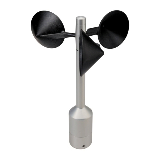
- Page 1 Wind Transmitter >>First Class Advanced X<< Instruction for Use 4.3352.00.400 / 401 4.3352.10.400 / 401 - Classified according to IEC 61400-12-1 EDITION 2.0 (2017-03) At start of software version V3.08 Dok. No. 021814/03/21 T H E W O R L D O F W E A T H E R D A T A...
- Page 2 Safety Instructions • Before operating with or at the device/product, read through the operating instructions. This manual contains instructions which should be followed on mounting, start-up, and operation. A non-observance might cause: - failure of important functions - endangerment of persons by electrical or mechanical effect - damage to objects •...
-
Page 3: Table Of Contents
Table of contents Models ..........................6 Application ........................6 Setup and Mode of Operation ..................7 Standard Curve and Calibration Tables .................11 Case 1 Using Standard Characteristic Curve acc. to Classification ......12 Case 2 Using Current Calibration Table acc. to Classification ......... 15 Determine Occupied Calibration Tables .............. - Page 4 11.2.19 Command SM ....................49 11.2.20 Command SN ....................50 11.2.21 Command SR ....................50 11.2.22 Command SV ....................50 11.2.23 Command TR ....................51 11.2.24 Command UC ....................51 11.2.25 Command WC ....................52 11.3 Command Interpreter MODBUS RTU ..............53 11.3.1 Measured Values (Input Register) ..............54 11.3.2 Commands (Holding Register) ...............62 11.3.3...
- Page 5 Figure: Figure 1: Connections between parameters FO, MS and UC ..........8 Figure 2: Curve of a calibration table and normal curve ............11 Figure 3: Data output after calibration E433524X0 2.3 in order to have frequency output at pin 1 according to the classification with standard characteristic curve ......13 Figure 4: Data output after calibration E433524X2 2.3 in order to have serial output according to the classification with standard characteristic curve ........14 Figure 5: Data output after calibration E433524X1 2.3 in order to have frequency output at...
-
Page 6: Models
1 Models Order no. Measuring Serial interface / Supply Heater Data format range 4.3352.00.400 0,3 ... 75m/s RS 485 / ASCII 3,7 … 42V DC 24V AC/DC, 25W 4.3352.10.400 0,3 ... 75m/s RS 485 / ASCII 3,7 … 42V DC without 4.3352.00.401 0,3 ... -
Page 7: Setup And Mode Of Operation
3 Setup and Mode of Operation The wind transmitter can be supplied with direct voltages from 3.7V up to 42V at very low power consumption. All of the electronics is a streamlined, low power design. Supply of the optional heater is provided separately with a direct or alternate voltage of 24V. The heater will most probably prevent icing/clogging of the wind transmitter First Class even under ex- treme meteorological conditions. - Page 8 Figure 1: Connections between parameters FO, MS and UC © Adolf Thies GmbH & Co. KG · Hauptstraße 76 · 37083 Göttingen · Germany 021814/03/21 Phone +49 551 79001-0 · Fax +49 551 79001-65 · info@thiesclima.com · www.thiesclima.com Page 8 of 86...
- Page 9 Instantaneous value: The instantaneous value is the gliding mean value of the last second. The scanning of the measuring values is carried out every 0.25s, and is not alterable. The measuring value, que- ried at any time, includes always the data of the last second measured in the moment of query.
- Page 10 ρ The angle is defined as angle between the x-axis (north – south axis), and the horizontal. Φ The angle is defined as angle between the y-axis (west – east axis), and the horizontal. θ The angle is the angle between the z-axis, and the vertical. Based on the angle, frequency and acceleration (amplitude), a qualified mast monitoring is possible.
-
Page 11: Standard Curve And Calibration Tables
4 Standard Curve and Calibration Tables The measured frequency is converted into a wind velocity (in proportion to the velocity of the cup star) with the standard curve: • 0462 y: Wind velocity in [m/s] f: Frequency in [Hz] Note: At frequencies less then 2Hz will be set the wind velocity to 0m/s. -
Page 12: Case 1 Using Standard Characteristic Curve Acc. To Classification
If the measured actual wind velocity is between 2 entries of the table, the wanted target wind velocity is determined by linear interpolation. If the measured actual wind velocity is outside the table range, the Bit2 is set in the status word and the standard curve is interpolated as follows: Is the measurement below the curve range, we have to interpolate between the start- ing point of the standard curve and the first table value. - Page 13 Figure 3: Data output after calibration E433524X0 2.3 in order to have frequency output at pin 1 according to the classification with standard characteristic curve © Adolf Thies GmbH & Co. KG · Hauptstraße 76 · 37083 Göttingen · Germany 021814/03/21 Phone +49 551 79001-0 ·...
- Page 14 Figure 4: Data output after calibration E433524X2 2.3 in order to have serial output according to the classification with standard characteristic curve © Adolf Thies GmbH & Co. KG · Hauptstraße 76 · 37083 Göttingen · Germany 021814/03/21 Phone +49 551 79001-0 · Fax +49 551 79001-65 · info@thiesclima.com · www.thiesclima.com Page 14 of 86...
-
Page 15: Case 2 Using Current Calibration Table Acc. To Classification
For using frequency output (pin 1) next steps are as following: Id. For operation, set FO4, UC0 Ie. Collect data from frequency output. With this setting, you will get wind velocity corrected by standard characteristic curve and air pressure (so classification and calibration are applicable). - Page 16 Figure 5: Data output after calibration E433524X1 2.3 in order to have frequency output at pin 1 according to the classification with current calibration table © Adolf Thies GmbH & Co. KG · Hauptstraße 76 · 37083 Göttingen · Germany 021814/03/21 Phone +49 551 79001-0 ·...
- Page 17 Figure 6: Data output after calibration E433524X3 2.3 in order to have serial output according to the classification with current calibration table © Adolf Thies GmbH & Co. KG · Hauptstraße 76 · 37083 Göttingen · Germany 021814/03/21 Phone +49 551 79001-0 · Fax +49 551 79001-65 · info@thiesclima.com · www.thiesclima.com Page 17 of 86...
-
Page 18: Determine Occupied Calibration Tables
For using frequency output (pin 1) next steps are as following: IIf. For operation, set FO4, UC1 IIg. Collect data from frequency output. With this setting, you will get wind velocity corrected by current calibration table and air pressure (so classification and calibration are applicable). -
Page 19: Write Calibration Table
4.5 Write Calibration Table Writing a calibration table is done with the command WC. With the parameter, the address to be written, and target and actual value of the sampling point (or calibration certificate num- ber or user string or date/time) will be specified. The written table entry is delivered back with the response telegram. -
Page 20: Integrated Corrections
<id>WC<Parameter><CR> Parameter = 34;uuuuuuuuuuuuuuu; Write user string Return value = tt;aa;uuuuuuuuuuuuuuuu uuuuuuuuuuuuuuuu = user-defined text <id>WC<Parameter><CR> Parameter = 35;YYYY.MM.DD;HH:NN:SS; Return value = tt;aa;YYYY.MM.DD;HH:NN:SS Write date/time tt = table aa = 35 (address for date/time) YYYY: Year MM: Month DD: Day HH: Hour NN: Minute SS: Second... -
Page 21: Recommendation Side Selection / Standard Installation
6 Recommendation Side Selection / Standard Installation In general, wind measuring instruments are supposed to record wind conditions over a large area. According to international regulations, the surface wind should be measured at a height of 10m above even open terrain, in order to achieve comparable values. An open terrain is defined as terrain where the distance between the wind-measuring instrument and the next obstacle is at least ten times the height of this obstacle (acc. -
Page 22: Mechanical Mounting
7.1 Mechanical Mounting Note: The wiring must be prepared so far, that plug and cable have been pushed through instru- ment carrier, mast, traverse etc., and can be connected to the wind transmitter at the mo- ment of the „Mechanical Mounting”, described in the following (please refer also to chapter 7.2). -
Page 23: North Alignment
The wind transmitter must be mounted on an instrument carrier, which is suited for the measurement. For dimensions of wind transmitter please refer to chapter 14. Tools: Hexagon socket wrench SW3 (Allen key). Procedure: 1. Lead a prepared cable with assem- bled plug through the bore hole of mast, tube, arm etc., and connect it to the wind transmitter. -
Page 24: Electrical Mounting
7.2 Electrical Mounting 7.2.1 Cable Solder a shielded cable with diameter 7-8mm and a core cross-section of 0.5...0.75mm² to the enclosed coupling socket. • The number of necessary wires is given in the connection diagram (chapter 7.3). 7.2.1.1 Cable Recommendation No. - Page 25 7.2.2.1 Connection recommendation for the cable shield Sensor Carrier Sensor Shielding / Ground Lightning Protection 1. Metallic measure- Isolated mounting at Apply the cable shield Mount metallic lightning ment mast, grounded the measuring mast between sensor and protection rod on the (e.g.
-
Page 26: Plug And Cable Mounting
7.2.3 Plug and Cable Mounting Coupling socket, Type: Binder, Serial 423, EMC with cable clamp Cable connection: with cable shield 1. Stringing parts on cable acc. to plan given Cable mounting 1 above. View X 2. Stripping cable sheath 20mm Cutting uncovered shield 15mm Stripping wire 5mm. -
Page 27: Connecting Diagram
7.3 Connecting Diagram Connection diagram acc. to chapter 7.2.2.1 no.1, 3 and 4: Order– No. View on the sol- dered joint of the counter 4.3352.00.400 plug 4.3352.00.401 4.3352.10.400* 4.3352.10.401* *Order-No. 4.3352.10.xxx (without heating) Pin 7 u. 8 are not connected Contact Name Function... -
Page 28: Maintenance
8 Maintenance If properly installed, the instrument requires no maintenance. Heavy pollution can lead to blockage of the slot between the rotating and the stable parts of the transmitter. Thus, it is advisable to remove the accumulated dirt from the instrument. Cleaning For the cleaning of the device should use a damp cloth without chemical cleaning agents are used. -
Page 29: Bootloader
10 Bootloader The Software in the device consists of two components: - bootloader - firmware The program part "Bootloader" cannot be changed and is performed each time the device is started. The behavior of the boot loader depends on the parameter "FB" (fast boot): Command: FB=0 The bootloader waits approx. -
Page 30: Interface
11 Interface The interface to the wind transmitter consists of an RS485 connection (half duplex mode) with the following data format: • 9600 baud (the baud rate can be set with the Command BR). • 8 data bits. • No parity. •... -
Page 31: Command Interpreter Thies
11.1 Command Interpreter THIES The wind transmitter is equipped with the command interpreter from the type THIES that can change the behavior of the device. E.g. the averaging period for the wind velocity can be changed. Basically, the command has the following structure: •... -
Page 32: Telegram Formats
In order to avoid an accidental parameter setting, some commands (see command list) are protected by a password. This password must be sent prior to the actual command. Example: Change of the baud rate 00KY234<CR> enable commands of the user level 00BR4<CR>... -
Page 33: Check Sum
11.1.2 Check Sum: The check sum is the XOR link of all characters between <XTX> and the byte <*>. The asterisk is the separation character of the check sum and is not contained in the check sum. 11.1.3 Status Information: Within the wind transmitter, the status word (32bit) is available which provides information about the condition of the transmitter. -
Page 34: Commands And Description
Bit number Function Description Bit 17…19 Source mean value calcu- The bits 17 to 19 show the wind velocity used for the cal- lation culation of the mean values. 000: Wind velocity calculated by the standard characteritic curve. 001: Wind velocity calculated by the calibration charact. curve. - Page 35 Command Initial MODBUS Description Password value Register Reading Factory address Writing setting Command SH 40039 Station height Without User Command SM Power saving mode Without User Command SN 40007 Read serial number Without Without Command SR 40029 Scanning rate (1s, 1/2s, Without User 1/4s)
-
Page 36: Command Br
11.2.1 Command BR <id>BR<parameter><CR> Setting the baud rate Access: reading / writing Description: With the command BR, the desired baud rate is set. Parameter type: unsigned integer Parameter: Parameter Description 1200baud 2400baud 4800baud 9600baud 19200baud 38400baud 57600baud Type return value: unsigned integer Return value: see parameter... -
Page 37: Command Ci
11.2.3 Command CI <id>CI<parameter><CR> Selection of the command interpreter. Access: reading / writing Description: With the command CI, the desired command interpreter is set. Note: If the identification number (ID) is bigger than 98, it is au- tomatically set to 0 when switching over into the THIES in- terpreter! Note: If the identification number (ID) equals 0, a switch-over... -
Page 38: Command Fb
11.2.5 Command FB <id>FB<parameter><CR> Quick start mode Access: reading / writing Description: The command selects the quick start mode or the set mode is queried. Parameter type: unsigned integer Parameter: 0: Quick start mode off 1: Quick start mode on Type return value: unsigned integer Return value:... -
Page 39: Command Hp
11.2.7 Command HP <id>HP<parameter><CR> Reference variable Sensor temperature control unit. Access: reading / writing Description: The pressure and acceleration sensors are thermally coupled and can be heated. The "HP" command sets the setpoint for the Sensor temperature controller. The information is given in °C with one decimal place. Parameter type: unsigned integer Parameter:... -
Page 40: Command Id
11.2.9 Command ID <id>ID<parameter><CR> Identification number. Access: reading / writing Description: This command sets the identification number (THIES inter- preter) or the slave address (MODBUS RTU interpreter). Only if the id included in the command corresponds to the one set in the wind transmitter, a response telegram is sent. -
Page 41: Command Kx
11.2.10 Command KX <id>KX<parameter><CR> With the command KX the command KY password can be changed Access: writing Description: The command KX sets the password for write access to the pa- rameters of command KY. A value other than 0 overwrites or replaces the password levels "User"... -
Page 42: Command Ky
11.2.11 Command KY <id>KY<parameter><CR> Key/password Access: reading / writing Description: With this command, the value for the key (password) is set. The following 3 password levels are possible: Query (reading) User (general settings) Calibration data (access to the calibration data sets) KX (general settings / access to the calibration data sets) Parameter type: unsigned integer... -
Page 43: Command Mi
11.2.12 Command MI <id>MI<parameter><CR> Averaging interval Access: reading / writing Description: With this command, the averaging interval for floating averaging of the wind velocity is set in seconds (see Bit4 in the sensor sta- tus). Wind velocity values are logged 4 times per second (4 Hz) for averaging. -
Page 44: Command Oh
11.2.14 Command OH <id>OH<CR> Read operating parameters Access: reading Description: With this command, the following operating parameters can be read: Number of the operating hours. Number of revolutions. Operating time since the last reset. Parameter type: unsigned integer Parameter: Parameter Description Number of the operating hours. -
Page 45: Command Rc
11.2.15 Command RC <id>RC<parameter><CR> Read calibration table. Access: reading Description: With the command, the table indicated in the parameter is read. The value returned by the command RC depends on the pa- rameter: Parameter type: unsigned integer Parameter: Parame- Description Table (0 ... - Page 46 Transfer Return value parame- ASCII representation Description <STX> Date/time of all tables (1...10) tt;YYYY.MM.DD;HH:NN:SS; tt;YYYY.MM.DD;HH:NN:SS; tt: Table tt;YYYY.MM.DD;HH:NN:SS; YYYY: Year tt;YYYY.MM.DD;HH:NN:SS; MM: Month tt;YYYY.MM.DD;HH:NN:SS; DD: Day tt;YYYY.MM.DD;HH:NN:SS; HH: Hour tt;YYYY.MM.DD;HH:NN:SS; NN: Minute tt;YYYY.MM.DD;HH:NN:SS; SS: Second tt;YYYY.MM.DD;HH:NN:SS; tt;YYYY.MM.DD;HH:NN:SS; <ETX> <STX>error<ETX> unequal 1...10 / Value range: Initial value:...
-
Page 47: Command Rs
11.2.16 Command RS <id>RS<parameter><CR> Reset Access: reading / writing Description: The RS command queries the reset source (le-send without pa- rameters) or performs a reset / restart (writing with parameter). The following reset sources can be output: PORF (Power On Reset Flag) EXTRF (External Reset Flag) BORF... -
Page 48: Command Sh
11.2.18 Command SH <id>SH<parameter><CR> Station height Access: reading / writing Description: With the command, the station height on the site is set on the site of the anemometer. This value is used for the calculation of the relative air pressure. The information of the height is given in meter. -
Page 49: Command Sm
11.2.19 Command SM <id>SM<parameter><CR> Power saving mode Access: reading / writing Description: The command enables reading and setting the power saving mode. Parameter type: unsigned integer Parameter: 0: all modules active 1: µC and interfaces disabled (frequency output active, when FO = 7) After activation of power-saving mode the sensor cannot be op- erated via the serial interface after approx. -
Page 50: Command Sn
11.2.20 Command SN <id>SN<parameter><CR> Serial number Access: reading Description: The command enables reading the serial number. Parameter type: Parameter: Type return value: unsigned integer Return value: xxxxxxxxxx: Serial number Value range: xxxxxxxxxx Initial value: 11.2.21 Command SR <id>SR<CR> Scanning rate Access: reading / writing Description:... -
Page 51: Command Tr
11.2.23 Command TR <id>TR<parameter><CR> Measured value request. Access: reading Description: The command activates the one-time transfer of the current data telegram. Parameter type: unsigned integer Parameter: Query measured value telegram 1 Query measured value telegram 2 Query measured value telegram 4 Query measured value telegram 5 Query measured value telegram 6 Query measured value memory telegram... -
Page 52: Command Wc
11.2.25 Command WC <id>WC<parameter><CR> Describe calibration table. Access: writing Description: With the command, the memories of the next free table are writ- ten. After writing date/time (address 35), the table is complete and no longer be changed. The table is selected automatically for writing access, in as- cending order from table 1 to table 10. -
Page 53: Command Interpreter Modbus Rtu
11.3 Command Interpreter MODBUS RTU If the command interpreter MODBUS RTU is selected, the transferred bytes are interpreted according to the MODBUS specification (http://www.modbus.org/). In this case, the wind transmitter represents a MODBUS slave. The data is transferred in packages in so called frames with max. 256 bytes. Each package contains a 16bit CRC check sum (initial value: 0xffff). -
Page 54: Measured Values (Input Register)
11.3.1 Measured Values (Input Register) All measured values of the wind transmitter occupy 32bit, i.e. 2 MODBUS register addresses. The table below shows the assignment of measured value to register address, whereby the measured values are sorted as follows: • According to measured value type (30001 to 34999). - Page 55 Regis- Parameter name Unit Multipli- Explanation Data type ter ad- cator dress 30803 Relative air pressure (35023) Value / 100 (2 decimal places e.g. 105000=1050.00hP 34811 32-bit sensor status in hexadeci- Value mal representation (no decimal place, a: high nibble in high byte in HEX bit coded, depend- (Bit 31 …...
- Page 56 Regis- Parameter name Unit Multipli- Explanation Data type ter ad- cator dress (no decimal place, e.g. 24=24mg) 34833 Frequency vibration measure- Value / 100 ment, Z-axis (35045) (2 decimal places e.g. 2400=24.00Hz) 34835 Acceleration vibration measure- Value ment, Z-axis (35047) (no decimal place, e.g.
- Page 57 Regis- Parameter name Unit Multipli- Explanation Data type ter ad- cator dress 105000=1050.00hP 35025 Sensor status Value (34811) (no decimal place, bit coded, depend- ing on sensor) 35027 Main loop run per 1s Value (no decimal place, e.g. 2550=2550 1/s) 35029 Operating time after reset Value...
- Page 58 Regis- Parameter name Unit Multipli- Explanation Data type ter ad- cator dress 35059 Temperature of the pressure sen- °C Value / 10 (1 decimal place, e.g. 355=35.5°C) 35100 Time since the last measured Value value query (no decimal place, e.g. 2550=2550ms) 35102 Measured value [0] (most re-...
- Page 59 Regis- Parameter name Unit Multipli- Explanation Data type ter ad- cator dress 35117 Measured value [15] (oldest) ac- Value / 10 cording to UC (1 decimal place, e.g. 101=10.1m/s) 36001 Wind speed Value / 10 Uncorrected (30005) (1 decimal place, e.g.
- Page 60 Regis- Parameter name Unit Multipli- Explanation Data type ter ad- cator dress Inclination angle θ Angle be- 36209 ° Value / 10 tween the Z-axis and the vertical (1 decimal place, (34819) e.g. 240=24.0°) Inclination angle ρ 36211 ° Value / 10 Angle between the X-axis and (1 decimal place, the horizontal plane (34821)
- Page 61 Note: At start from 36001, the MODBUS master can read out all measured values corresponding to the data telegram 4 with one request! Note: At start from 36101, the MODBUS master can read out all measured values corresponding to the data telegram 5 with one request! Note: At start from 36201, the MODBUS master can read out all...
-
Page 62: Commands (Holding Register)
11.3.2 Commands (Holding Register) All commands of the wind transmitter occupy 32bit, i.e. 2 MODBUS register addresses and represent unsigned integers. The following example shows the change of the baud rate to 19200 baud. 1. Set password for the user level (KY=234) Slave Functional Start... -
Page 63: Reading Time Stamp Of All Calibration Tables
Regis- Parameter Name Value range Meaning File Authoriza- ter-ad- type tion type dress 41456 6. Newest Calibration table 152 Byte(s) Read calibration data Read … 41531 41532 7. Newest Calibration table 152 Byte(s) Read calibration data Read … 41607 41608 8. -
Page 64: Reading Calibration Tables
Byte bit location time infor- mation Byte 3 Seconds Table 7: Reading Time : The first transmitted byte. : The last transmitted byte. 11.3.5 Reading Calibration Tables Reading out the MODBUS register of addresses 41000 to 41835 delivers the calibration tables (41006-41075 standard characteristic line). - Page 65 Byte Parameter Byte 26 Actual-Wind-Velocity-Address 7 (Resolution: 0.01m/s) Byte 27 Byte 28 Target-Wind-Velocity-Address 8 (Resolution: 0.01m/s) Byte 29 Byte 30 Actual-Wind-Velocity-Address 8 (Resolution: 0.01m/s) Byte 31 Byte 32 Target-Wind-Velocity-Address 9 (Resolution: 0.01m/s) Byte 33 Byte 34 Actual-Wind-Velocity-Address 9 (Resolution: 0.01m/s) Byte 35 Byte 36 Target-Wind-Velocity-Address 10...
- Page 66 Byte Parameter Byte 72 Target-Wind-Velocity-Address 19 (Resolution: 0.01m/s) Byte 73 Byte 74 Actual-Wind-Velocity-Address 19 (Resolution: 0.01m/s) Byte 75 Byte 76 Target-Wind-Velocity-Address 20 (Resolution: 0.01m/s) Byte 77 Byte 78 Actual-Wind-Velocity-Address 20 (Resolution: 0.01m/s) Byte 79 Byte 80 Target-Wind-Velocity-Address 21 (Resolution: 0.01m/s) Byte 81 Byte 82 Actual-Wind-Velocity-Address 21...
- Page 67 Byte Parameter Byte 118 Actual-Wind-Velocity-Address 30 (Resolution: 0.01m/s) Byte 119 Byte 120 Target-Wind-Velocity-Address 31 (Resolution: 0.01m/s) Byte 121 Byte 122 Actual-Wind-Velocity-Address 31 (Resolution: 0.01m/s) Byte 123 Byte 124 Target-Wind-Velocity-Address 32 (Resolution: 0.01m/s) Byte 125 Byte 126 Actual-Wind-Velocity-Address 32 (Resolution: 0.01m/s) Byte 127 Byte 128 Calibration certificate number...
-
Page 68: Device Identification (Read Device Identification)
11.3.6 Device identification (Read Device Identification) The wind transmitter supports the MODBUS function 0x2B (Read Device Identification) with the MEI type 0x0E. This enables the MODBUS Master to recognize the wind transmitter. Function: 0x2B / 0x0E (Read Device Identification) MEI type: 0x0E Read Device ID code: 1, 2, 3 (stream access) -
Page 69: Appendix 1 Data Telegrams
12 Appendix 1 Data Telegrams 12.1 Telegram 1 The wind transmitter responds with the measured value telegram to the command “00TR1\r”. The table below shows the telegram structure: Position Length Example Description Start character (start of text) Identification number (ID) xx: 0…99 Separation character (’;’) xx.x... - Page 70 Position Length Example Description Separation character (’;’) yxx.x Temperature of pressure and acceleration sensor (unit: °C) y: Sign (+ or -) xx.x: Temperature value; resolution: 0.1°C; MODBUS-Register: 35059 Separation character (’;’) xxxx.x Absolute air pressure (unit: hPa) xxxx.x: Pressure value; resolution: 0.1hPa; MODBUS-Register: 30801 Separation character (’;’) xxxx.x...
- Page 71 Position Length Example Description abcdefgh 32-bit sensor status in hexadecimal representation a: high nibble in high byte in HEX (Bit 31 … 28) b: low nibble in high byte in HEX (Bit 27 … 24) c: high nibble in byte 2 in HEX (Bit 23 … 20) d: low nibble in byte 2 in HEX (Bit 19 …...
-
Page 72: Telegram 2
12.2 Telegram 2 The wind transmitter responds with the measured value telegram 2 to the command “00TR2\r”. The table below shows the telegram structure: Position Length Example Description Start character (start of text). Identification number (ID) xx: 0..99 Separation character (’;’) xx.xx Instantaneous value of the wind velocity, calculated with current calibration table;... -
Page 73: Telegram 4
Position Length Example Description e: high nibble in byte 3 in HEX (Bit 15 … 12) f: low nibble in byte 3 in HEX (Bit 11 … 8) g: high nibble in low byte in HEX (Bit 7 … 4) h: low nibble in low byte in HEX (Bit 3 …... -
Page 74: Telegram 5
Position Length Sample Description y: low nibble checksum in HEX End character (end of text) Carriage return (Carriage Return) Line feed Table 12: Value-Telegram 4 Pressure and acceleration sensors are thermally coupled. 12.4 Telegram 5 The wind sensor responds to the command "00TR5 \ r" with the measured value telegram. The telegram structure is shown in the following table: Position Length... -
Page 75: Telegram 6
Pressure and acceleration sensors are thermally coupled. 12.5 Telegram 6 The wind sensor responds to the command "00TR6 \ r" with the measured value telegram. The telegram structure is shown in the following table: Position Length Sample Description Start of text Identification number (ID) xx: 0…99 Separation marks (’;’) -
Page 76: Measured Value Memory Telegram
Position Length Sample Description Separation marks (’;’) xxxx Acceleration vibration measurement, y-axis (unit: mg) xxxx: acceleration; Resolution: 1mg Separation marks (’;’) xxx.x Frequency vibration measurement, z-axis (unit: Hz) xxx.x: frequency; Resolution: 0.1Hz Separation marks (’;’) xxxx Acceleration vibration measurement, z-axis (unit: mg) xxxx: acceleration;... - Page 77 Position Length Example Description xxx.x Measured value (4); unit: m/s; resolution: 0.1m/s Separation character (’;’) xxx.x Measured value (5); unit: m/s; resolution: 0.1m/s Separation character (’;’) xxx.x Measured value (6); unit: m/s; resolution: 0.1m/s Separation character (’;’) xxx.x Measured value (7); unit: m/s; resolution: 0.1m/s Separation character (’;’) xxx.x Measured value (8);...
- Page 78 In the order interpreter “MODBUS RTU”, the ring buffer is readable via one of the following addresses: Register address Description 35100 Time since the last measured value query in ms 35102 Most recent measured value (0) 35103 Measured value (1) 35104 Measured value (2) 35105...
-
Page 79: Technical Data
13 Technical Data Characteristics Description Measurement range 0.3 ... 75m/s Measurement uncertainty ±1% from the measured value or < ±0,2m/s @ 0,3 ... 50m/s Survival velocity 80m/s (min. 30 minutes) Admissible -40 ... +80°C environmental conditions 0 ... 100% relative humidity, including condensation Housing inside temperature Measurement range: -40 …... -
Page 80: Faq - Frequently Asked Questions
Characteristics Description Wind load Approx. 100 N @ 75m/s Heater Surface temperature of the housing neck >0°C at 20m/s to -10°C air temperature, at 1 0m/s to -20°C Use of the Thies icing standard 012002 on the housing neck Heater controlled with temperature sensor. Electric supply for Voltage: 3.7 ... -
Page 81: Dimensional Drawing
15 Dimensional Drawing © Adolf Thies GmbH & Co. KG · Hauptstraße 76 · 37083 Göttingen · Germany 021814/03/21 Phone +49 551 79001-0 · Fax +49 551 79001-65 · info@thiesclima.com · www.thiesclima.com Page 81 of 86... -
Page 82: Accessories (Optional)
16 Accessories (optional) Traverse 0.6m 4.3174.00.000 Horizontal sensor distance: 0.6m Vertical sensor distance: 0.2m For mounting the wind ve- Mast receptacle: 48 … 50mm locity and wind direction Material: Aluminum, anodized transmitter jointly onto a Dimensions: tube Ø 34x4mm, mast. 668mm long, 756mm high Hanger 4.3184.01.000... - Page 83 Example: Wind transmitter with traverse 4.3174.00.000 and lightning rod 4.3100.98.000 © Adolf Thies GmbH & Co. KG · Hauptstraße 76 · 37083 Göttingen · Germany 021814/03/21 Phone +49 551 79001-0 · Fax +49 551 79001-65 · info@thiesclima.com · www.thiesclima.com Page 83 of 86...
-
Page 84: Ec-Declaration Of Conformity
Tel.: (0551) 79001-0 Fax: (0551) 79001-65 email: Info@ThiesClima.com This declaration of conformity is issued under the sole responsibility of the manufacturer Description of Product: Windsensor First Class Advanced II, Windsensor First Class Advanced X Article No. 4.3352.00.000 4.3352.10.000 4.3352.00.400 4.3352.10.400 4.3352.00.401... - Page 85 © Adolf Thies GmbH & Co. KG · Hauptstraße 76 · 37083 Göttingen · Germany 021814/03/21 Phone +49 551 79001-0 · Fax +49 551 79001-65 · info@thiesclima.com · www.thiesclima.com Page 85 of 86...
- Page 86 Please contact us for your system requirements. We advise you gladly. ADOLF THIES GMBH & CO. KG Meteorology and environmental metrology Hauptstraße 76 · 37083 Göttingen · Germany Phone +49 551 79001-0 · Fax +49 551 79001-65 info@thiesclima.com www.thiesclima.com © Adolf Thies GmbH & Co. KG · Hauptstraße 76 · 37083 Göttingen · Germany 021814/03/21 Phone +49 551 79001-0 ·...
Need help?
Do you have a question about the First Class Advanced X and is the answer not in the manual?
Questions and answers