Table of Contents
Advertisement
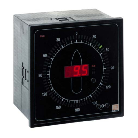
Wind Indicator LED
Instruction for Use 4.3223.xx.x50
1. General Information
The Wind Indicator LED is a state-of-the-art indicator unit which displays both the wind direction and the
wind speed parameters. It is extremely reliable, flexible and offers optimal display.
Thanks to its compact construction and a system of integrated self-test functions, the Wind Indicator unit is
very reliable - an important quality. Moreover, its flexibility is guaranteed owing to the versatile connection
possibilities available on it to transmit the wind parameters; different wind transmitters can be connected or
the wind parameters can be transmitted over an optional serial interface.
Displayed are the True or the Relative Wind. The data for both wind values are received by serial telegrams
(NMEA-format).
Calculated and displayed are the instantaneous values of the wind speed and the wind direction. Moreover,
you can choose between 3 other modes of displaying the wind direction and its variation (see chapter 3.
Setting the Wind Indicator LED on page 7.
There are 3 different units for wind speed: m/s, kn , Beaufort (Bft). You can control the brightness of the
displays manually or automatically in a wide range.
Table of contents
1.
General Information
1.1
1.2
2
2.1
2.2
2.3
3
4
4.1
4.2
4.3
4.4
4.5
4.6
4.7
4.8
5
6
1- 18
021229/07/01
Advertisement
Table of Contents

Related Manuals for Thies CLIMA 4.3223.50 Series


Summary of Contents for Thies CLIMA 4.3223.50 Series
-
Page 1: Table Of Contents
Wind Indicator LED Instruction for Use 4.3223.xx.x50 Table of contents General Information Versions of the Indicator Elements of the Indicator Installation Power supply Wind transmitter input Serial interface Setting the Wind Indicator LED Operating the Wind Indicator LED Selecting the units Controlling the brightness Testing the LED’s (Soft reset) Remote control... -
Page 2: Versions Of The Indicator
1.1 Versions of the Indicator figure 1 In this (ship-) version of the Wind Indicator LED the display of the wind direction is scaled linear from 0 degrees at north over east (starboardside) to 180 degrees at south with green LED's and in the same way over west (portside) to 180 degrees at south with red LED's. -
Page 3: Elements Of The Indicator
4.3223.1x.xxx In this version the Wind Indicator LED is equipped with one terminal strip for wind transmitters (see in figure on page 5). 4.3223.2x.xxx In this version the Wind Indicator LED is equipped with two terminal strips for one wind transmitter and ad- ditional Wind Indicators LED. -
Page 4: Installation
2. Installation The electrical connections are located on the back panel of the display. Fuse DIP-switch Changeover switch 230V/115V 3 pole Option 2 terminal strip 12 pole power supply terminal strip 12 pole Option 1 terminal strip 9 pole D plug transmitter input Size of the opening: 138 mm x 138 mm figure 2... -
Page 5: Wind Transmitter Input
2.1 Power supply Terminal Strip: 230V / 115V AC 24V DC at 4.3223.x0.xxx at 4.3223.x2.xxx mark Function Function phase null not connected The Wind Indicator LED 4.3223.x0.000 operates from a 230 VAC as well as 115 VAC 50 Hz or 60 Hz mains supply. -
Page 6: Serial Interface
2.3 Serial interface (4.322x.xx.1xx or 4.322x.xx.2xx) For the different versions of the Wind Indicator LED with a serial interface see chapter Versions of the Indicator on page 2. The electrical connection for the serial interface is a 9-pole D-plug (male, see figure on page 4): Function RX (RS232) TX (RS232) -
Page 7: Setting The Wind Indicator Led
3. Setting the Wind Indicator LED The Wind Indicator LED has a number of different routine functions and different instrument versions which can be set on the back panel of the instrument by means of a DIP-switch. DIP-switch: 1 2 3 4 5 6 7 8 switches S1 - S8 Wind Indicator version Land version... - Page 8 life-zero error control error control on error control off The life-zero error control is switched off through the switch-function S5 = OFF for all wind sensor models. Therefore no error information E03, E04, E05. S6 switches two functions: the master/slave modus and the serial data input/output. Master / Slave Modus Serial data input Slave...
-
Page 9: Operating The Wind Indicator Led
4. Operating the Wind Indicator LED The Wind Indicator LED is operated from the front with optical sensor keys. These keys are located behind the front pane. This pane of glass protects the instrument from dust. The sensor keys respond to the contrast between the reflected and the direct radiation resulting when the surface of the sensor is touched. -
Page 10: Selecting The Units
4.1 Selecting the units The unit of wind speed can be switched as desired by touching the optical sensor key OSK 3 (see figure3) with your fingers. The unit switches once a second as long as the sensor key remains activated. After switching on the indicator (hard reset) or the LED test (soft reset), you will get the unit selected at last. -
Page 11: Remote Control
4.4 Remote control The Wind Indicator LED can be operated from an external point. The precondition for this is that no 8 bit or 6 bit parallel wind transmitter has been connected (see chapt. 3. Setting the Wind Indicator LED on page 7). The following pins on the terminal strip can be used for the operation: Terminal Strip Function... -
Page 12: Serial Protocol
4.6 Serial protocol (4.322x.xx.1xx , 4.322x.xx.2xx) Standard Adjustment : Receive: 1200…9600Bd **1 ** The eighth recieving bit will not be evaluated. 1 stopbit Therefore, the following receipt is possible: 8N1, 7E1, 7O1, 7M1 The baud rate can be selected in the following operation modes of the wind indicator LED: Dip-Switch Input Wind Data seriell Wind Transmitter... -
Page 13: Specification Nmea Protocol
4.7.1 Specification NMEA Protocol Receive of the NMEA-Protocol: greatest receivable length between “$” and <CR>: 26 characters between the 2 possible telegrams (true/relative) should be a time gap of at least 50ms $WIMWV,XXX.X,R,XXX.X,N,A*HL<CR><LF> Checksum (see 4.8) Status: A= Data valid; a=data valid and display relation;V=error * Unit WS: N = kn;... -
Page 14: Troubleshooting
5. Troubleshooting The Wind Indicator LED has a number of error control routines which are automatically carried out during the switch on phase of the instrument i.e. while the instrument is in operation. If an error occurs, this is indicated on the wind speed display in the form of an error code. - Page 15 Error code Error Cause / Remedy Remark track E,F,G,H (x=1,2,4,8) internal error (return instrument) V cc (wind transmitter) error internal error (return instrument) U ref error internal error (return instrument) watch-dog error internal error (return instrument) WD = Wind direction WS = Wind speed Remarks: 1.
-
Page 16: Technical Data
6. Technical Data • two colour LED's (red, green) for the wind direction Display: • size of LED 2 x 5 mm • 3-digit 7-segment display for the wind speed • height of digits 15 mm • text fields for the units (m/s, kn, Beaufort) •... - Page 17 • identification of a break in the supply line by measurement of the supply Test functions: current of the wind transmitters • identification of a break in the line for parallel wind direction transmitters by "life-zero“ signal • identification of a break in the line for synchronous-serial wind direction transmitters by software •...
- Page 18 ADOLF THIES GmbH & Co. KG Hauptstraße 76 37083 Göttingen Germany P.O. Box 3536 + 3541 37025 Göttingen Phone ++551 79001-0 Fax ++551 79001-65 www.thiesclima.com info@thiesclima.com - Alterations reserved - 18- 18 021229/07/01...
Need help?
Do you have a question about the 4.3223.50 Series and is the answer not in the manual?
Questions and answers