Table of Contents
Advertisement
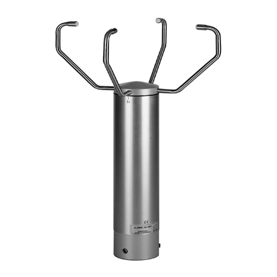
Ultrasonic Anemometer 2D
Operating Instructions 4.3800.00.940
1. Range of Application
The Ultrasonic Anemometer 2D is designed to detect the horizontal components of wind speed and wind
direction in two dimensions as well as the virtual temperature. Due to its very short measurement intervals,
the instrument is ideal for the inertia-free measurement of gusts and peak values.
In certain weather situations the accuracy of the air temperature measurement (virtual-temperature)
surpasses that one of the classic method where the temperature transmitter is used in a weather and thermal
radiation shield.
The measured data are available as analogue signals and as a data telegram via a serial interface.
The ultrasonic transducers as well as its carrying arms are automatically heated so that the measuring
results, in case of critical ambient temperatures, are not affected by icing rain or snow.
2. Mode of Operation
The Ultrasonic Anemometer 2D consists of 4 ultrasonic transducers, in pairs of 2 which are opposite each
other at a distance of 200 mm.
The two measurement paths thus formed are vertical to each other.
The transformers act both as acoustic transmitters and acoustic receivers.
The respective measurement paths and their measurement direction are selected via the electronic control.
When a measurement starts, a sequence of 4 individual measurements in all 4 directions of the
measurement paths is carried out at maximum possible speed.
The measurement directions (acoustic propagation directions) rotate clockwise, first from south to north, then
from west to east, from north to south and finally from east to west.
The mean values are formed from the 4 individual measurements of the path directions and used for further
calculations.
A measurement sequence takes approx. 10 msec at +20°C.
1 -12
021235/10/01
Advertisement
Table of Contents

Subscribe to Our Youtube Channel
Related Manuals for Thies CLIMA Ultrasonic Anemometer 2D


Summary of Contents for Thies CLIMA Ultrasonic Anemometer 2D
- Page 1 2. Mode of Operation The Ultrasonic Anemometer 2D consists of 4 ultrasonic transducers, in pairs of 2 which are opposite each other at a distance of 200 mm.
-
Page 2: Measurement Principle
3. Measurement Principle 3.1 Wind speed and direction The speed of propagation of the sound in calm air is superposed by the speed components of an air flow in Wind from NNE wind direction. A wind speed component in the direction of the propagation of the sound supports the speed of propagation, thus leading to an increase in the speed. -
Page 3: Technical Data
4. Technical Data Wind Speed Meas. range 0...65 m/s, the analogue outputs are scaled to 60 m/s ! ± 0.1 m/s , at the range 0 ... 5 m/s Accuracy resp. ± 2 % rms from meas. value , at > 5 m/s Resolution 0.1 m/s Meas. - Page 4 5.1 Remarks concerning Power Supply of Instrument: The connecting cables for the heating (13 u. 14; 15 u. 16) must be bridged on the supply side in order to guarantee the complete heating power! The electronics is additionally supplied uncoupled via diodes through the heating connections 13,14, and 15, If the heating voltage exceeds the supply voltage the heating voltage takes on the supply of the electronics.
- Page 5 6.1.3 Telegram V4DT (STX)xxx.x xxx xxx.x x xx*xx(CR)(ETX) Z. NR. FUNCTION STX (HEX 02) Wind speed Wind speed Wind speed (HEX 2E) Decimal point Wind speed Spare (HEX 20) Wind direction Wind direction Wind direction Space (HEX 20) + or - Sign Temperature Temperature (HEX 2E) Decimal point...
- Page 6 6.2 Definition of Checksum and Status byte 6.2.1 Forming of Checksum The checksum is the result of the byte-wise EXOR-combination of the bytes output in the telegram. The EXOR-combination comprises all bytes between the telegram start sign „STX”, or “$” within the NMEA- telegram, and the byte “*”...
- Page 7 7. Averaging Procedure: The Ultrasonic 2D forms the gliding mean value through a FIFO-memory the capacity of which comprises up to 600 values. In the free running measurement mode the measurement data rate is exactly 10 Hz or 100msec, and forms, at the same time, the updating rate for the averaging memory (FIFO-memory).
- Page 8 8. Bus-Ability, Synchronisation of the Measurement on the Query Telegram: 8.1 Duplex-Mode The Ultrasonic supports absolutely any operation at an RS485/RS422 data bus in co-operation with further instruments (bus operation). Supported are both semi-duplex bus-topologies and full duplex bus-systems. In the semi- and full duplex operation the line drivers of the Ultrasonic are active only for the time of data transmission.
-
Page 9: List Of Commands
9. List of control commands The Anemometer 2D can be controlled via its serial data interface using the commands in the following list. Any standard terminal program such as “procomm“ , “telix“ or a Windows terminal program (e.g. “Hyper Terminal” ) can be used. All adjustments are stored in a E²ROM so that the adjusted parameters cannot get lost after switching off or failure of power supply. -
Page 10: Command Input
Due to the compatibility the telegrams VD and VDT supply the wind speed in 3 digits form In order to avoid that the measuring range is exceeded the telegrams deliver the wind speed exclusively in the unit of m/s (meters per second)! 9.2 Command Input Please find your ID (identifier-number) in the works certificate included in the delivery. -
Page 11: Preparation For Use
10. Preparation for Use 10.1 Selecting the Site As already described above the ultrasonic anemometer transmits sonic bursts which are necessary for the measurement of the propagation speed. If these sonic bursts hit a well sonic-reflecting surface they are reflected as echo and might cause error measurements – under unfavourable conditions. It is, therefore, advisable to install the US-anemometer with a minimum distance of 1 meter to objects in the measurement area. -
Page 12: Maintenance
12. Maintenance As the instrument has no moving parts i.e. operates without wear or tear, only minimal maintenance is required. As the sensor surface is permanently washed up by the falling rain it is only occasionally necessary to clean the surface with non-aggressive cleansing agent and soft cloth. These cleansing activities can be carried out –...
Need help?
Do you have a question about the Ultrasonic Anemometer 2D and is the answer not in the manual?
Questions and answers