Table of Contents
Advertisement
Quick Links
Advertisement
Table of Contents

Related Manuals for Thies CLIMA 9.2750.xx.90 Series


Summary of Contents for Thies CLIMA 9.2750.xx.90 Series
- Page 1 Operating Instructions 021503/10/07 Weather Display LED 9.2750.xx.90x ADOLF THIES GmbH & Co. KG Hauptstraße 76 37083 Göttingen Germany Box 3536 + 3541 37025 Göttingen Phone ++551 79001-0 Fax ++551 79001-65 www.thiesclima.com info@thiesclima.com...
-
Page 2: Table Of Contents
Contents Device Versions ......................... 3 Application ..........................3 View ............................5 Mode of Operation ........................5 Calculation of sliding mean and extreme values: ..............5 Calculation of Sums ......................6 Elevation Input to the Air Pressure (Function only with instrument 9.2750.1x.901) .... 6 Acquisition of measured values................... -
Page 3: Device Versions
1 Device Versions Operating Designation Order No. Equipment voltage Weather Display 9.2750.00.90 Input/output 1 x RS422 230 V AC; 24 V AC; 12…35 V DC Weather Display 9.2750.01.90 Input/output 1 x RS422 115 V AC; 24 V AC; 12…35 V DC Weather Display 9.2750.00.90 Input/output 1 x RS422... - Page 4 The device version 9.2750.xx.901 also has an analog interface. This provides for the connection of measured value transmitters with an analog output. The device version 9.2750.1x.901 is additionally equipped with an integrated pressure sensor for the acquisition of barometric air pressure data. Equipment with device 9.2750.0x.900: •...
-
Page 5: View
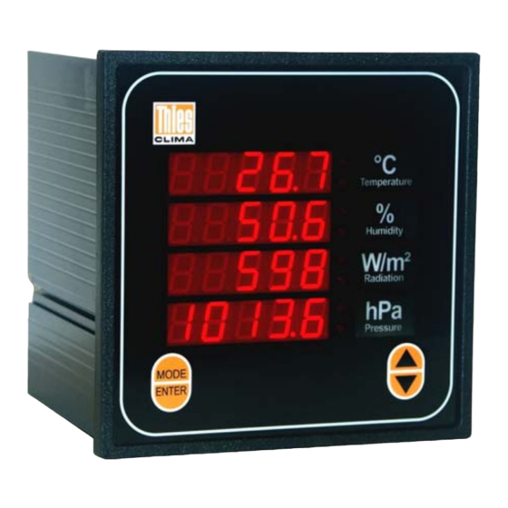
3 View 4 x 5-digit Min/Max LEDs LED displays Button "INFO & RESET" "Dimension" Button "UP" Button "MODE" Button Button "DOWN" 4 Mode of Operation 4.1 Calculation of sliding mean and extreme values: To process the sliding measured values two ring buffers with a depth of 60 single values are available for each measured value. -
Page 6: Calculation Of Sums
The ring buffers are initialised whenever the Weather Display is started up. The first valid measured value is written to the ring buffers so that a measured value appears in the display at once. A regular extreme or mean value is then available after the time selected. The times selected are not synchronised to the clock time. -
Page 7: Acquisition Of Measured Values
4.4 Acquisition of measured values The acquisition of measured values is carried out via the serial interface (RS422) or optionally the analog inputs. The parameters required are filtered out of the data protocol received or the analog values and assigned to the relevant LED displays. Configuration of the Weather Display LED is carried out at the factory. -
Page 8: Recommendation For Selection Of Site
If no telegram is received, the following message will appear after 10 sec "E09" =Time out E 0 9 E 0 9 E 0 9 5 Recommendation for Selection of Site The device is designed for indoor installation. When used outdoors, an additional external housing including the appropriate type of protection is required. -
Page 9: Electrical Installation / Connections
6.2 Electrical installation / connections: All connections are at the rear (see Fig. 1 and 2). No function Windsensor AC-Power Pulse X7 Termination In (RS422) Down Data Clock Enter Mode Remote control Res. X8 Termination Out Power Supply TX - 230V 1A TX + 115V 2A... -
Page 10: Connection Of Serial Interface Rs422
6.2.1 Connection of serial interface RS422 • The Weather Display LED is equipped with 1x RS422 Input / Output. Weather Display LED Input Output COM 1, COM COM 1, COM 1’ 1’ The baud rate for the interface is set using the buttons on the front of the Weather Display LED (see Section 8). -
Page 11: Fig. 3: Example Of Connection
Windsensor ocit Pulse ecti Data Clock Jumper TX - Rear panel TX + Weather Display-LED RX - RX + TX - TX + RX - RX + Transmitter e.g. data logger Jumper Fig. 3: Example of connection Information for RS422: Faults on long cables may affect serial transmission may affect serial transmission, with the serial interface possibly being destroyed by over voltages. -
Page 12: Connection Of Analog Inputs (9.2750.Xx.901)
6.2.2 Connection of analog inputs (9.2750.xx.901) • For external measured value transmitters with analog output for acquisition of weather parameters: Clamping plug: Analog input Clamping plug: Temp Des. Des. (weather parameters) (temperature) CH1+ V, mA CH1- V, mA Pt100 in 4-wire circuit CH2+ V, mA CH2-... -
Page 13: Connection Of Power Supply
6.2.5 Connection of power supply • For Weather Display 9.2750.x0.900 / 901 Clamping plug: Clamping plug: Des. Des. AC-Power low voltage Power Protective conductor 24V AC/DC 230V AC 24V AC/DC 230V AC • For Weather Display 9.2750.x1.900 / 901 Clamping plug: Clamping plug: Des. -
Page 14: Data Output Protocol
7 Data Output Protocol The output protocol contains all four display parameters. They are output in the display sequence 1 ... 4 and in the display format. e.g. Weather Display protocol: (STX)xxx.x xxx.x xxx.x xxxxx*HL(CR)(ETX) - ' ' is used as a separator - Erroneous parameters are replaced by "???.."... -
Page 15: Operation
8 Operation The display is operated using the buttons on the front (s. Fig. 4). Whenever a button is pressed, this is acknowledged by an acoustic signal. The Table of operating functions summarises the operations possible. The MODE button is used to navigate through the 3 operator control levels (Mode 0-2). - Page 16 Input menu Display Digits Real-time clock (h) rtc h Real-time clock (m) rtc n Real-time clock (s) rtc S Baro station height ALtI The menus are displayed in levels 1 & 2. e.g. b A u d 1 2 0 0 Menu structure: The Weather Display LED has 3 operating modes: Mode 0 (Display mode):...
- Page 17 Mode 1 & Mode 2 (Programming mode): Mode 1&2 are accessed by pressing the button "MODE" for over 3 sec. Modes 1&2 differ from each other as follows: Mode 1: Select menus of preset parameters Mode 2: Editing of parameters Each level can be assigned one or more select or input menus, which are accessed using the button "MODE"...
- Page 18 Level 1..4 Mode2: Input baro- station height Menu x Table of operating functions: Mod 0 Mod 1 Mod 2 Button Function ▲▼ Dim display Save brightness value Max ▲ & ENTER ▼ & ENTER Save brightness value Min Call up brightness value Max ▲...
- Page 19 Functions of MIN and MAX LEDs: The display status of the MIN & MAX LEDs is listed below as a function of the operating mode: Operating mode LED MIN ▼ LED MAX ▲ Function / Status Display of instantaneous value Display of MIN value Display mode Display of MAX value...
- Page 20 5. Selection of the Display Line (Totals Formation) Press button „ MODE“ and hold it until this procedure is acknowledged by an “acoustic signal” (approx. 3sec.). Selective menu 1 (bAudr) appears in the display. Press button „ MODE“ as often until the selective menu 5 (Su) appears in the display. Press button “▲”(UP) until „...
- Page 21 Press button "ENTER" and select parameter to be changed. r t c h The first digit flashes and can now be changed with button "▲" button "▼" Press button "MODE" once and the second digit flashes. Use button "▲" button "▼" to change the digit.
- Page 22 Table: Device parameters Device parameters Display Software Version No. (e.g.) r 1.1 Baud rate 1200 2400 4800 9600 19200 b192 57600 b576 COM profile Sliding extreme value time 1min Et 1n 10min Et10n 30min Et30n Et 1h Et 2h Et 6h Et12h Et24h Sliding mean value time...
-
Page 23: Functional Test
9 Functional Test When the device is started up or the button INFO & RESET pressed (see Section 8), the Weather Display LED executes a number of test procedures. In the event of an error an error code appears in the display (see Section 10). Testing serial interface: When started up, the Weather Display LED transmits a single test protocol. -
Page 24: Error Messages
10 Error Messages If an error is detected in operation, an error code will be shown in the display for at least 3 seconds or as long as the error is present. Error Error Comment/Action code Internal Vcc 5V Device defective: Send in 1. -
Page 25: Maintenance
11 Maintenance The Weather Display LED is maintenance-free. Cleaning To clean the face plate and housing a dampened cloth should be used without chemical cleaning agents. Storage The Weather Display LED must be stored in a dry room free of dust at temperatures between -20.. + 50°C. -
Page 26: Technical Data
12 Technical Data Description Display Type LED, red Display 4 x 5-digit LED, height 14mm 4 x Min/Max identifiers (LED – arrow) Display range - 9.999 ...+ 99999 Interfaces Serial interface 1 serial interface (EN 61162-1) Type RS422 Data format Output 7E1, 8N1, 7O1 Input... - Page 27 RTC (Clock) Puffer time ca. 2h Accuracy ±20 ppm Aging max. ±5 ppm/year Instrument functions Extreme value time 1min, 10min, 30min, 1h, 2h, 6h, 12h, 24h Mean value time no, 1min, 10min, 30min, 1h, 2h, 6h, 12h, 24h no, display-Z.1, display-Z.2, display-Z.3, display-Z.4 General Mains...
-
Page 28: Dimension Drawing
13 Dimension Drawing Control panel cut-out nach DIN x 138 Terminals 2 fixing brackets on right and left Slid into housing/rear panel at rear and screwed into place 28 - 30 021503/10/07... -
Page 29: Ec-Declaration Of Conformity
14 EC-Declaration of Conformity Document-No.: 002005 Month: 11 Year: 07 A D O L F T H I E S G m b H & C o. K G Manufacturer: Hauptstr. 76 D-37083 Göttingen Tel.: (0551) 79001-0 Fax: (0551) 79001-65 email: Info@ThiesClima.com Description of Product: Weather Display LED Article No. - Page 30 ADOLF THIES GmbH & Co. KG Hauptstraße 76 37083 Göttingen Germany P.O. Box 3536 + 3541 37025 Göttingen Phone ++551 79001-0 Fax ++551 79001-65 www.thiesclima.com info@thiesclima.com - Alterations reserved - 30 - 30 021503/10/07...
Need help?
Do you have a question about the 9.2750.xx.90 Series and is the answer not in the manual?
Questions and answers