Table of Contents
Advertisement
Quick Links
Instruction for Use
021546/12/17
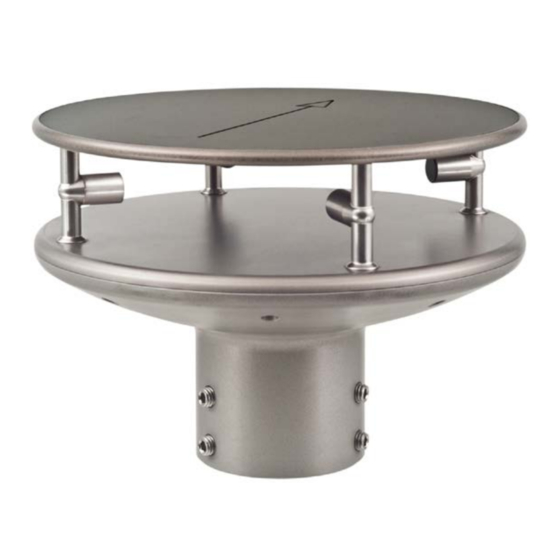
Ultrasonic Anemometer 2D compact
4.387x.xx.xxx
from software version V3.11
Status: 10/2017
ADOLF THIES GmbH & Co. KG
Hauptstraße 76
37083 Göttingen Germany
Box 3536 + 3541
37025 Göttingen
Phone +49 551 79001-0
Fax +49 551 79001-65
www.thiesclima.com
info@thiesclima.com
Advertisement
Table of Contents

Subscribe to Our Youtube Channel
Related Manuals for Thies CLIMA 4.387 Series


Summary of Contents for Thies CLIMA 4.387 Series
- Page 1 Instruction for Use 021546/12/17 Ultrasonic Anemometer 2D compact 4.387x.xx.xxx from software version V3.11 Status: 10/2017 ADOLF THIES GmbH & Co. KG Hauptstraße 76 37083 Göttingen Germany Box 3536 + 3541 37025 Göttingen Phone +49 551 79001-0 Fax +49 551 79001-65 www.thiesclima.com info@thiesclima.com...
- Page 2 Safety Instructions • Before operating with or at the device/product, read through the operating instructions. This manual contains instructions, which should be followed on mounting, start-up, and operation. A non-observance might cause: - failure of important functions - Endangering of persons by electrical or mechanic effect - Damages at objects •...
- Page 3 Patent Protection This instrument is patent-protected Patent No.: EP 1 448 966 B1 Patent No.: US 7,149,151 B2 Operating Instructions These operating instructions describe all possible applications and settings of the instrument. The Ultrasonic Anemometer 2D compact is factory-set. Identification for the factory setting derives from the order No. and the respective "Factory Setting" Order number and Setting see supplementary sheet "Factory Setting"...
-
Page 4: Table Of Contents
Contents Models available ......................6 Application ........................7 Mode of Operation ......................8 Measuring Principle: Wind velocity and direction ..............8 Measuring principle: Acoustic virtual temperature ............... 9 Measuring principle: Air pressure (optional) ................ 9 Heating ..........................9 Preparation for operation ..................... 10 Selection of installation site .................... - Page 5 Behaviour in Case of Error....................29 8.6.1 Behaviour of analogue outputs ................... 29 8.6.2 Behaviour of telegram output ..................29 Output of all system parameters ..................30 Enquiry about software version ..................30 Forcing a restart ....................... 30 8.10 Energy-saving mode ......................30 8.11 Plausibility ........................
-
Page 6: Models Available
Table 8 : MODBUS Frame ......................49 Table 9 : MODBUS Exceptions ..................... 49 Table 10 : MODBUS Input Register ....................52 Table 11 : List of commands MODBUS RTU Interpreter ..............53 1 Models available Description Article- No. * Parameter Output / Interface/ Equipment 4.3875.0X.XXX... -
Page 7: Application
2 Application The Ultrasonic Anemometer 2D compact is used to detect the horizontal components of wind velocity and wind direction in 2 dimensions in particular sturdy design. In addition, the virtual temperature is measured. Optionally, the measurement of the “atmospheric air pressure (absolute)” is possible. The instrument is especially suited for application in the fields of •... -
Page 8: Mode Of Operation
3 Mode of Operation The Ultrasonic Anemometer 2D compact consists of 4 ultrasonic transformers, in pairs of two facing each other at a distance of 200 mm. The two resulting measurement paths are vertical to each other. The transformers function both as acoustic transmitters and receivers. The electronic control system is used to select the respective measurement path and its measuring direction. -
Page 9: Measuring Principle: Acoustic Virtual Temperature
3.2 Measuring principle: Acoustic virtual temperature The thermodynamic interrelationship between the propagation velocity of sound and the absolute temperature of the air is defined by a root function. The sound velocity is also more or less independent of the air pressure and only depends on the absolute air humidity to a minor extent. This physical interrelationship between sound velocity and temperature is ideal when measuring the air temperature as long as the chemical composition is known and constant. -
Page 10: Preparation For Operation
Thus, icing is safely avoided, for example, at a temperature of -20 °C up to a wind velocity of 10 m/s. Functionality: Heating foils and transistors are activated by a temperature sensor at an appropriate position inside the housing via a two-level-controller, thus providing for a constant temperature at the outside surfaces of approx. -
Page 11: Installation Of Anemometer
In general, wind meters should register wind conditions over a wide area. To obtain comparable values when measuring the ground wind, measurement should be performed at a height of 10 metres above even and undisrupted terrain. Undisrupted terrain means that the distance between the wind transmitter and the obstruction should be at least ten times the height of the obstruction (s. -
Page 12: Alignment To North / Positioning
4.3 Alignment to north / Positioning North Alignment (Positioning) of the Anemometer at a Weather Station For the accurate determination of the wind direction, the anemometer must be positioned to the north. Procedure: 1. „Position“ the ultrasonic anemometer by rotating on the mast tube until the ... -
Page 13: Electrical Installation For Ultrasonic Anemometer
Positioning of an Anemometer on a Wind Power Plant For the exact determination of the wind direction the anemometer must be mounted in alignment with the generator hub. Procedure (at generator hub north): 1. „Position“ the ultrasonic anemometer by rotating on the mast tube, until the orientation arrow (in parallel to the generator axis) indicates towards the generator-hub. -
Page 14: Cables, Cable Preparation, Connector Installation
4.4.1 Cables, Cable preparation, Connector Installation For pin assignment please refer to supplement „factory settings“. Examples see chapter 3.4.2. The cable must have the following properties: 8 cores; 0.5 … 0.75 mm² core cross-section for supply ; min. 0.14 mm² core cross-section for data communications ;... -
Page 15: Connector Pin Assignment (Examples Of Function)
4.4.2 Connector Pin Assignment (Examples of Function) Remark: - For exact allocation of function please refer to supplement “Factory Settings” - The pins 1 – 6 (incl.) are galvanically isolated from the supply voltage and from housing. • View of solder terminal Serial Interface, Full-duplex of coupling socket Pin Allocation... -
Page 16: Maintenance
5 Maintenance As the instrument does not have moving parts, i.e. is not subject to wear during operation, only minimal servicing is required. The instrument is subject to natural pollution, the level of pollution depends on the location. If necessary the instrument and the sensor surfaces can be cleaned from soil Cleaning can be carried out as required using non-aggressive cleaning agents in water and a soft cloth during routine checks. -
Page 17: Functional Description
8 Functional description The functioning of the ULTRASONIC instrument is described below. Due to the limited number of plug connections some functions exclude the simultaneous operation with other functions. Such dependency is described in each case. There are also restrictions regarding the functional definition of the cable connector. -
Page 18: Response Delay
A half-duplex-mode can be selected via the Command DM (duplex mode). With this mode, on principle, the line-transmitter is switched on only when sending. For the full-duplex-operation there are two modes: one for bus operation (RS485), where the line-transmitter is controlled as in half- duplex mode, and another one (RS422), where the line-transmitter remains active even in case of reception. -
Page 19: Saving Of The Ultrasonic Parameters
Examples: 1. Telegram number 2 shall be queried. The respective command is: 00TR2<cr> <cr> stands for Carriage Return (enter button) alternatively also: 00TR00002<cr> can be entered. 2. Query of baud rate with the command: 00BR<cr> <cr> stands for Carriage Return (enter button) the selected data record for the baud rate is returned. -
Page 20: Access Mode
8.1.6 Access Mode For configuration the ULTRASONIC has a set of commands, which determine behaviour in terms of the propagation time. The commands are broken down into three levels: • Query Mode • User mode • Configuration mode Enquiry mode (“READ ONLY“): This mode comprises commands, which do not influence the parameters of the ULTRASONIC. -
Page 21: Baud Rate
Example: 00KY1 switch into „USER ACCESS“ mode !00KY00001 response from ULTRASONIC Setting rights -> USER response from ULTRASONIC 00AV5 command for changing averaging time frame !00AV00005 response from ULTRASONIC New Averaging time frame: response from ULTRASONIC 00KY0 command for the „READ ONLY“ mode !00KY00000 response from ULTRASONIC Setting rights ->... -
Page 22: Bus Mode
Example: 00KY4711 Command for access allowance !00KY04711 response from ULTRASONIC Setting rights -> ADMIN response from ULTRASONIC 00ID00004 Changing of IC into address 4 !00ID00004 response from ULTRASONIC The ULTRASONIC responds now to the now ID ‚04’. For permanent ID changing see chapter 8.1.4. 04AV Query of the averaging time by new ID !04AV00005... -
Page 23: Scaling Of Analogue Wind Velocity
8.2.1 Scaling of analogue wind velocity With the analogue wind velocity the user has the option of specifying the velocity for the terminal value of the measuring range with the command AR. In the preset value the scaling is 0..60m/s: Command AR. -
Page 24: Serial Data Output
The Ultrasonic 2D compact incorporates two different practical procedures for averaging: • one procedure for generating vectorial mean values and • one procedure for generating scalar mean values These different procedures can be selected for averaging wind velocity as well as wind direction depending on the actual application. -
Page 25: Independent Telegram Output
8.4.2 Independent telegram output Independent telegram output is selected using the command TT. After a valid telegram type has been input, the ULTRASONIC independently transmits the data telegram selected. The transmission interval is set in ms using the command OR. The telegram is transmitted every 100ms as standard. -
Page 26: Generation Of Check Sum
8.4.4 Generation of check sum The check sum is the result of the byte wise EXOR link of the bytes output in the telegram. The EXOR link encompasses all bytes between the telegram start character "STX", or "$" with the NMEA telegram and the byte "* "... - Page 27 1: Buffer 1/8 < x ≤ 1/8 filled Bit 11 2: Buffer 1/8 < x ≤ 3/16 filled 3: Buffer 3/16 < x ≤ 1/4 filled 4: Buffer 1/4< x ≤ 5/16 filled 5: Buffer 5/16 < x ≤ 3/8 filled 6: Buffer 3/8 <...
- Page 28 8.4.5.2 THIES Status The THIES status is structured bit wise. The individual bits in the status value have the following meanings: Bit number Function Description Bit 0 General Averaging time < 30 s An error is output when no new measured malfunction preset see „ET“...
-
Page 29: Behaviour Of Instrument Under Extreme Conditions Of Measurement Value Acquisition
8.4.5.4 Voltage Supply Monitoring Byte The Sonic Voltage is calculated in the following way: Byte Range(Hex): 00…ff Vsupply = Value * 0.25 V Example: Voltage Byte = 64(hex) Vsupply = 100 * 0.25 V = 25.0 V Note: At AC supply the peak value will be shown, not RMS. 8.5 Behaviour of Instrument under extreme Conditions of Measurement Value Acquisition The ULTRASONIC is equipped with a highly effective internal fault detection and correction system. -
Page 30: Output Of All System Parameters
8.7 Output of all system parameters Most parameters of the ULTRASONIC are stored internally in an EEPROM. The command SS can be used to output all stored parameters. Before amending parameters it is recommended making a backup copy of existing settings and storing them in a text file: see also Command SS. -
Page 31: Online Help
8.12 Online help For a short description of commands the ULTRASONIC contains an Online help, which provides information about individual commands. The Help text for the command is returned by inputting the command and a '?'. The help text for all commands is output when: 00?? <cr>... -
Page 32: Thies Command Interpreter
10 Thies Command Interpreter 10.1 List of Commands Thies Interpreter Command Description Command AD <id>AD<para5> Setting the delay time of individual measurement (Acquisition Delay) Command AM <id>AM<para5> Setting of average mode. Command AO <id>AO<para5> Analogue output mode Command AR <id>AR<para5> Scaling of analogue wind velocity output (Analogue Range) Command AS <id>AS<para5>... -
Page 33: Command And Description
10.2 Command and description Command AD <id>AD<para5> Setting the delay time of individual measurement (Acquisition Delay) Access: Configuration mode (ADMIN) Description: This command sets the time period from the beginning of a propagation time Measurement (TOF) up to the following TOF (repetition rate of TOF measurements) Value range: 2 ... - Page 34 Command AR <id>AR<para5> Scaling of analogue wind velocity output (Analogue Range) Access: Configuration mode (ADMIN) Description: Determines the end of measuring range for the output of the analogue wind velocity. The standard ULTRASONIC scales the wind velocity as follows: 0 ... 10 V (2 ... 10 V) correspond to 0 ... 60 m/s It might also be reasonable to scale the wind velocity from 0 ...
- Page 35 The averaging memory is designed as a sliding memory. On start-up the data of the averaging memory are instantly valid. Averaging is performed immediately using the measured values available. Value range: 0 ... 1200 Initial value: Command BP <id>BP<para5> Defines the parity of the interface baud rate (Baud rate Parity) Access: Configuration mode (ADMIN) Description:...
- Page 36 Command BT <id>BT<para5> Bus termination Access: Configuration mode (ADMIN) Description: Command for connecting a terminating resistor of approx. 120 ohm on the RS485 lines. Parameter description: bus termination off. bus termination on. Initial value: depending on instrument Command CI <id>CI<para5> Selection of the Command Interpreters Access: Configuration mode (ADMIN)
- Page 37 It is only possible to switch from half duplex to full duplex mode with the following prerequisites: • The PINs WG/RXD- and WR/RXD+ must not be selected as analogue outputs Command AO Parameter description: Half duplex mode (RS485, transmission drivers are switched off if no data sent.
- Page 38 Command ET <id>ET<para5> Time in s, until the generic error bit is set (Error Timeout). Access: Configuration mode (ADMIN) Description: Determines after which time the generic error bit is set. The static error bit is set always when the generic error exists more than 60 s. Special case: with output rates (OR) <...
- Page 39 Command HP <id>HP<para5> Heating Power Access: Configuration mode (ADMIN) Description: With this command the maximum heating power can be pre-set. This command is only effective when the heating control is on (see command HT). Parameter description: Full heating power of all system heating, nominally 240 W. Alternating heating: cover plate + sensor receiving socket alternating to base plate, nominally 120 Reduced heating power:...
- Page 40 Switch-on temperature raised to +45 °C, is deactivated by control line to “high” level. Switch-on temperature raised to +45 °C, is deactivated by control line to “low” level Value range: 0 ... 8 Initial value: Command ID <id>ID<para5> ULTRASONIC ID Access: Configuration mode (ADMIN) Description:...
- Page 41 The user key protects parameters, which influence the behaviour of the ULTRASONIC, e.g. averaging period and baud rate. The user can change these parameters but he must realise that a change of the parameter will alter the behaviour of the ULTRASONIC. Before every change it is recommended using the command SS to output and save the current configuration.
- Page 42 Command OS <id>OS<para5> Scaling of wind velocity output (Output Scale) Access: Configuration mode (ADMIN) Description: This command is used to specify in which unit of measurement the wind velocity is output in the serial telegram. Different units of measurement are available for this purpose.
- Page 43 Command RS <id>RS<para5> Restart ULTRASONIC (Reset) Access: Configuration mode (ADMIN) Description: With transmission of this command the ULTRASONIC is restarted by the watchdog.. Parameter description: The ULTRASONIC performs a warm start. It behaves as after connection of the supply voltage. The ULTRASONIC does no longer operate the watchdog.
- Page 44 Command SH <id>SH<para5> Station height for calculation of the air pressure on mean sea level Access: Configuration mode (ADMIN) Description: Entry of station height in meters above sea level for conversion of air pressure on sea level. Parameter description: 0 ... 9000: Station height in meters (basis for the conversion of air pressure on sea level) This parameter is used only with the Ultrasonic Compact 4.3875.2X.XXX !
- Page 45 Command SS <id>SS<para5> System status (System Status) Access: Query mode Description: Outputs the selected parameters of all commands. All parameters stored in the EEPROM are output here. Before parameters of the ULTRASONIC are changed, this command should be used to generate and save a list of the selected parameters, e.g. by copying parameters to a text file.
- Page 46 Command TG <id>TG<para5> Trigger characteristic of the control line (TriGger) Access: Configuration mode (ADMIN) Description: Definition of the necessary voltage status for controlling the telegram output via the sensor control line, see also Command PU. When using the trigger for the telegram output, first the requested telegram should be selected by means of “TT”, and afterwards the output rate (parameter “OR”) must be reset, so that the telegram is output only in case of a trigger event.
- Page 47 Command TR <id>TR<para5> Telegram Request (Telegram request) Access: Query mode Description: The command TR is used to specifically request a telegram from the ULTRASONIC. After interpretation the ULTRASONIC sends back the requested telegram. The instrument specifies a series of predefined telegrams, as well as option for the user to configure his own telegram: see Fixed telegram formats, User-specific telegram.
- Page 48 Command WW <id>WD<UUULLL> Wind Warning Access: Configuration mode (ADMIN) Description: It specifies the Pull Up on/off criterion of the control pin, see PU. UUULLL -> 'UUU' upper and 'LLL' lower threshold of velocity criterion in steps of 0.1m/s Rising wind speed exceeding upper threshold enables the criterion and descending wind speed below lower threshold disables the criterion.
-
Page 49: Modbus Rtu Command Interpreter
11 MODBUS RTU Command Interpreter In the MODBUS RTU command interpreter the transmitted bytes are interpreted acc. to the MODBUS specification (http://www.modbus.org/). The Ultrasonic is a MODBUS Slave instrument. The data transmission is carried out in packages, so-called frames, with a max. length of 256 bytes. Each package includes a 16bit CRC check-sum (initial value: 0xFFFF). -
Page 50: Command Description
11.2 Command Description The commands of the Ultrasonic occupy 32bit, i.e. 2 MODBUS register addresses, and stand for unsigned integral numbers. The following example shows the changing of baud rate to 19200 baud with subsequent permanent storing of the parameter. 1. - Page 51 30803 Relative air pressure value / 100 referred to mean sea 0x7853 (2 decimal places, e.g. level 105000=1050.00 hPa) 34601 Date Wert 0x8729 (no decimal place, JJJJMMTT, e.g. 20121210=10.12.2012) 34603 Time value (no decimal place, 0x872B HHMMSS, e.g. 121035=12:10:35) 34811 Sensor status see sensor status chapter 6.2.4...
- Page 52 35019 Time value 0x88CB (34603) (no decimal place, HHMMSS, e.g. 121035=12:10:35) 35021 Sensor status see sensor status chapter 6.2.4 0x88CD (34811) 35023 Sensor supply (34995) value /10 0x88CF (1 decimal place, e.g. 241=24.1 V) Live Counter 35025 value (34997) 0x88D1 (no decimal place, internal ms counter) 35027...
-
Page 53: Commands (Holding Register)
11.4 Commands (Holding Register) The following table shows the commands available with the appropriate passwords for writing. Command MODBUS Description Password Register address/ reading writing Protocol address Command AV 40015 / 14 Averaging interval for wind velocity and wind without Admin direction. -
Page 54: Appendix 1 Predefined Data Telegrams
12 Appendix 1 Predefined data telegrams 12.1 Telegram 1 Wind speed and wind direction Command: TR1 Command: TT1 Construction of telegram: VD (STX)xx.x xxx*xx(CR)(ETX) CH. NO. Function STX (HEX 02) wind velocity wind velocity decimal point (HEX 2E) wind velocity Blank character (HEX 20) wind direction wind direction... -
Page 55: Telegram 2 Vdt
12.2 Telegram 2 Wind speed, wind direction, acoustic-virtual temperature Command: TR2 command: TT2 Construction of telegram: (STX)xx.x xxx xxx.x xx*xx(CR)(ETX) CH. NO. FUNCTION STX (HEX 02) wind velocity wind velocity decimal point (HEX 2E) wind velocity Blank character (HEX 20) wind direction wind direction wind direction... -
Page 56: Telegram 3 Vd2
12.3 Telegram 3 Wind speed, wind direction with higher resolution Command TR3 Command: TT3 Construction of telegram: (STX)xxx.xx xxx.x*xx(CR)(ETX) CH. NO. FUNCTION STX (HEX 02) wind velocity wind velocity wind velocity decimal point (HEX 2E) wind velocity wind velocity Blank character (HEX 20) wind direction wind direction wind direction... -
Page 57: Telegram 00004 Nmea
12.4 Telegram 00004 NMEA NMEA V 2.0 Command: TR4 Command TT4 Construction of telegram: $WIMWV,xxx.x,R,xxx.x,N,A*xx(CR)(LF) CH. NO. FUNCTION (HEX 24) dollar (HEX 57) (HEX 49) (HEX 4D) (HEX 57) (HEX 56) (HEX 2C) comma wind direction wind direction wind direction (HEX 2E) decimal point wind direction (HEX 2C) -
Page 58: Telegram 7 Vx, Vy, Vt
12.5 Telegram 7 Vx, Vy, VT Wind velocity components Vx und Vy Command: TR7 Command: TT7 Construction of telegram: (STX)xxx.x;xxx.x;xxx.x;xx;xx(CR)(ETX) CH. NO. FUNCTION (HEX 02) + or - sign wind velocity X wind velocity X (HEX 2E) decimal point wind velocity X ;... -
Page 59: Telegram 8 Vdm
; (Semicolon) High Byte status byte Low Byte status byte ; (Semicolon) High Byte Check sum in HEX (1 ... 22) Low Byte Check sum in HEX (1 ... 22) CR (HEX 0D) Carriage Return ETX (HEX 03) 12.6 Telegram 8 Wind speed, wind direction with higher resolution and supply voltage monitor Command: TR8 Command: TT8... -
Page 60: Telegram 9 Vdpm
Decimal Point (HEX 2E) Blank Character (HEX 20) Decimal Point (HEX 2E) Blank Character (HEX 20) Status Byte (High Byte) Status Byte (Low Byte) Blank Character (HEX 20) Supply Voltage Monitor (HEX High Byte) Supply Voltage Monitor (HEX Low Byte) * (HEX 2A) checksum identifier High byte checksum in HEX (2 ... - Page 61 Supply-voltage-monitor (HEX High Byte) Supply-voltage-monitor (HEX Low Byte) * (HEX 2A) Checksum identifier High byte Checksum in HEX (2 ... 29) Low byte Checksum in HEX (2 ... 29) CR (HEX 0D) Carriage return ETX (HEX 03) Telegram output in case of error CH.
-
Page 62: Telegram 11 Pbt
12.8 Telegram 11 PBT Wind velocity, wind direction and acoustic-virtual temperature Command: TR11 Command: TT11 Telegram construction: (STX)xx.x xxx xxx.x xx*xx(CR)(ETX) Character No. Normal function Output in error case PBT (3 Bytes HEX 50 42 54) PBT as normal function Wind velocity in 1/10 m/s (2 byte binary) 0xFFFF (binary Low-Byte High-Byte) Wind direction in °... -
Page 63: Technical Data
13 Technical Data Wind velocity Measuring range 0.01 ... 75 m/s Scaling of analogue output freely selectable ≤5 m/s: ±0.2 m/s (rms, mean over 360 °) Accuracy 5 … 60 m/s: ±2 % of meas. value (rms- mean over 360 °) 60 …... - Page 64 Temperature Operating temperature –50 ... +80 °C heated range –30 ... +80 °C unheated Storing –50 ... +80 °C Measuring operation possible with heating up to -75 °C Operating voltage Supply U: 8 ... 60 V DC oder w/o heating 12 ...
-
Page 65: Dimension Drawing
14 Dimension Drawing Schraube / screw 4 x M8; 120° Positions- Bohrung / position drilling Ø:5mm; T:8mm Orientierungspfeil / orientation arrow 65 - 68 021546/12/17... -
Page 66: Accessories (Available As Optional Features)
15 Accessories (available as optional features) Connecting cable, complete 507751 15 m cable (Type: PUR/C/PP 4x0,75+2x2x0,14) with socket outlet on transmitter side. The other end of the cable is equipped with core identification rings PC-Program Meteo-Online 9.1700.98.000 For graphical display of measured values on a PC Interface converter 9.1702.xx.000 For RS 422 signal conversion in RS 232... -
Page 67: Ec-Declaration Of Conformity
16 EC-Declaration of Conformity Document-No.: 000607 Month: 12 Year: 17 A D O L F T H I E S G m b H & C o. K G Manufacturer: Hauptstr. 76 D-37083 Göttingen Tel.: (0551) 79001-0 Fax: (0551) 79001-65 email: Info@ThiesClima.com This declaration of conformity is issued under the sole responsibility of the manufacturer... - Page 68 ADOLF THIES GmbH & Co. KG Hauptstraße 76 37083 Göttingen Germany P.O. Box 3536 + 3541 37025 Göttingen Phone +49 551 79001-0 Fax +49 551 79001-65 www.thiesclima.com info@thiesclima.com - Alterations reserved- 68 - 68 021546/12/17...
Need help?
Do you have a question about the 4.387 Series and is the answer not in the manual?
Questions and answers