Advertisement
5.4.2
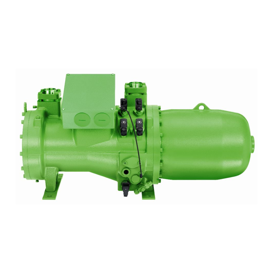
CM-SW-01
Standard for all CSW105 compressors
The compressor module integrates the entire electronic
periphery of the compressor: It allows monitoring the
essential operating parameters of the compressor: mo-
tor and discharge gas temperature, phase and rotation
direction monitoring, oil supply and application limits
and thus protects the compressor from operation under
ИНСТРУКЦИЯ ПО ЭКСПЛУАТАЦИИ
critical conditions. For further information, see Tech-
nical Information ST-150.
NOTICE
!
!
The compressor module may be damaged or
fail!
Never apply any voltage to the terminals of CN7
to CN12 – not even for test purposes!
The voltage applied to the terminals of CN13
Semi-hermetic compact screw compressors
must not exceed 10 V!
Translation of the original Operating Instructions
The voltage applied to terminal 3 of CN14 must
English.......................................................................................................................................................
not exceed 24 V! Do no apply voltage to the
other terminals!
Halbhermetische Kompaktschraubenverdichter
Originalbetriebsanleitung
The following components are completely installed and
Deutsch .....................................................................................................................................................
wired in the state of delivery:
Compresseurs à vis compacts hermétiques accessibles
Полугерметичные компактные винтовые компрессоры
• Slider position indicator.
Traduction des instructions de service d'origine
Перевод оригинальной инструкции по эксплуатации
• Oil monitoring (OLC-D1).
Français.....................................................................................................................................................
Русский ................................................................................................................................
• Solenoid valves for capacity control and V
• Discharge gas temperature sensor.
• Low pressure and high pressure transmitter.
Modification to these components or their wiring is not
CSH6553-35Y .. CSH6593-60Y
required and should not be done without consulting
CSH7553-50Y .. CSH7593-110(Y)
BITZER.
CSH8553-80Y .. CSH8593-180(Y)
The following components are not installed and wired in
the state of delivery and need to be connected:
CSH9553-180(Y) .. CSH95113-320Y
• Motor temperature monitoring (PTC sensor in motor
winding).
CSH7673-70Y .. CSH7693-90Y
• Phase monitoring (in case of a phase failure or inad-
CSH8673-110Y .. CSH8693-140Y
missibly high phase asymmetry).
CSH9663-160Y .. CSH96113-320Y
The compressor module internally supplies voltage to
the peripheral devices (solenoid valves, oil monitoring
device and slider position indicator) and to the terminal
CSK6151-50 .. CSK6161-60
strips CN7 to CN12.
Please refer to the Technical Information ST-150 for in-
formation on all connections.
SB-170-9
SB-170-9 RUS
5.4.3
SE-i1
This protection device with extended monitoring func-
tions can be used as an option for all HS.53 .. HS.85
compressors and CSH and CSW compressors.
Monitoring functions:
• Temperature monitoring.
• Monitoring of the PTC control circuit to detect any
short-circuit or line break/sensor failure.
• Rotation direction monitoring.
• Monitoring of phase failure and asymmetry.
• Monitoring of the maximum cycling rate.
For further information, see Technical Information
CT-110.
5.4.4
SE-E2
Optional protection device for operation with frequency
inverter and soft starter (for a ramp time shorter than
1 s).
• Dimensions and integration in the control identical to
SE-E1.
• Suitable for all CS. compressors.
• Monitoring functions are basically identical to those
of SE-E1. However, the SE-E2 monitors phase fail-
.
ure during the entire running time of the compressor.
i
For further information, see Technical Information
ST-122.
CSW6583-40Y .. CSW6593-60(Y)
5.4.5
Monitoring of the oil circuit
CSW7571-60Y .. CSW7593-90(Y)
• For short circuits without liquid injection (LI) for addi-
CSW8573-90Y .. CSW8593-140(Y)
tional cooling and for small system volume and small
refrigerant charge: Indirect monitoring with oil tem-
CSW9563-140Y .. CSW95113-320(Y)
perature sensor (standard)
CSW10593-400Y
NOTICE
!
!
Lack of oil leads to a too high increase in tem-
perature.
Risk of damage to the compressor!
• For circuits with liquid injection (LI) for additional
cooling and / or for great system volume as well as
parallel compounding: Monitor oil level directly with
opto-electronic oil level monitoring (option), see
chapter Opto-electronic oil level monitoring OLC-D1-
S, page 26. The connection is on the compressor
housing, see chapter Connections and dimensional
drawings, page 14, position 8.
SB-170-9 RUS
SB-170-9
2
35
68
68
Document for installers
Dokument für Monteure
Document pour des monteurs
Для монтажников
25
1
Advertisement
Chapters

Related Manuals for Bitzer CSH6553-35Y


Summary of Contents for Bitzer CSH6553-35Y
- Page 1 For further information, see Technical Information • Low pressure and high pressure transmitter. ST-122. Modification to these components or their wiring is not CSH6553-35Y .. CSH6593-60Y CSW6583-40Y .. CSW6593-60(Y) required and should not be done without consulting 5.4.5 Monitoring of the oil circuit CSH7553-50Y ..
-
Page 2: Table Of Contents
5.1 Raccordements réseau Table of contents Tenir compte absolument de l’ordre des bobinages par- tiels ! Lors du dimensionnement des contacteurs du moteur, 1 Introduction................................ 4 des conduites d'amenée et des fusibles : • 1er bobinage partiel (contacteur K1) : Raccords 1 / 1.1 Also observe the following technical documents .................. 4 2 / 3. - Page 3 5.4.5 Monitoring of the oil circuit BITZER. • For short circuits without liquid injection (LI) for addi- The following components are not installed and wired in tional cooling and for small system volume and small...
-
Page 4: Also Observe The Following Technical Documents
5.1 Raccordements réseau 1 Introduction 2.3 Safety references Tenir compte absolument de l’ordre des bobinages par- tiels ! Lors du dimensionnement des contacteurs du moteur, These refrigeration compressors are intended for incor- are instructions intended to prevent hazards. Safety ref- des conduites d'amenée et des fusibles : poration into refrigeration systems in accordance with •... -
Page 5: Application Ranges
5.4.5 Monitoring of the oil circuit Application limits CSH: see brochure SP-171 and BITZER SOFTWARE BITZER. • For short circuits without liquid injection (LI) for addi- CSW: see brochure SP-172 and BITZER SOFTWARE... -
Page 6: Vice Max
5.1 Raccordements réseau 3.1 Economiser and additional cooling Tenir compte absolument de l’ordre des bobinages par- R1234yf and R1234ze(E). They are considered as tiels ! technically tight. No ignition source assessment is Lors du dimensionnement des contacteurs du moteur, Compressors of the series CSH65 to CSH95 are available for other refrigerants of the A2L safety group. -
Page 7: Centres Of Gravity And Weights
Centre of gravity X (mm) Centre of gravity Y (mm) BITZER. • For short circuits without liquid injection (LI) for addi- CSH6553-35Y The following components are not installed and wired in tional cooling and for small system volume and small CSH6553-50(Y) -
Page 8: Seur D'un Côté Et, De L'autre, La Commutation Entre
5.1 Raccordements réseau Tenir compte absolument de l’ordre des bobinages par- CSH compressors Weight (kg) Centre of gravity X (mm) Centre of gravity Y (mm) tiels ! CSH7583-100(Y) Lors du dimensionnement des contacteurs du moteur, des conduites d'amenée et des fusibles : •... - Page 9 4.2.2 Marine application formation on all connections. chapter Opto-electronic oil level monitoring OLC-D1- side temperatures, etc.). Consultation with BITZER is S, page 26. The connection is on the compressor recommended. With regard to marine applications, defined diagonal housing, see chapter Connections and dimensional mounting on the longitudinal axis of the ship can be ne- drawings, page 14, position 8.
- Page 10 5.1 Raccordements réseau Mount the compressor in parallel to the longitudinal Tenir compte absolument de l’ordre des bobinages par- Installa- Inclination in the Inclination in the axis of the ship and tiels ! tion longitudinal direction transversal direction Lors du dimensionnement des contacteurs du moteur, static dynamic static...
-
Page 11: Connecting The Pipelines
5.4.5 Monitoring of the oil circuit NOTICE Cool the valve body and the brazing adapter BITZER. For systems with rather long pipelines or for • For short circuits without liquid injection (LI) for addi- during and after the brazing operation. -
Page 12: Moteurs À Bobinage Partiel (Pw) Méthodes De Démarrage
5.1 Raccordements réseau Additional connections for evacuation Mount pipelines in such a way that the compressor is Tenir compte absolument de l’ordre des bobinages par- protected from flooding with oil or liquid refrigerant dur- tiels ! Lors du dimensionnement des contacteurs du moteur, For an optimal evacuation capacity, it is recommended ing standstill. - Page 13 In part-load operation, the application ranges CAP ⇑ • Discharge gas temperature sensor. are limited! See manual SH-170 or BITZER For further information, see Technical Information CAP min. 50% ⇓ SOFTWARE.
-
Page 14: Connections And Dimensional Drawings
Ø12 / 1/2'') Effectuer correctement les raccordements ! Une erreur Risque d'endommagement de l'isolant et de dé- Fig. 8: Dimensional drawing CSH6553-35Y .. CSH6593-60Y, CSK6151 .. CSK6161 d’arrangement des raccords électriques aboutit à des faillance du moteur ! champs tournants contraires ou à l’angle de phase dé- Il ne faut surtout pas répéter l'essai de haute... - Page 15 Modification to these components or their wiring is not required and should not be done without consulting 5.4.5 Monitoring of the oil circuit BITZER. • For short circuits without liquid injection (LI) for addi- M22x1,5 2x 1 1/4-12 UNF 1/8-27 NPTF Ø22 (7/8'')
- Page 16 5.1 Raccordements réseau Tenir compte absolument de l’ordre des bobinages par- 3 (LP) tiels ! 1/8-27 NPTF Lors du dimensionnement des contacteurs du moteur, 1540 des conduites d'amenée et des fusibles : • 1er bobinage partiel (contacteur K1) : Raccords 1 / 2 / 3. •...
- Page 17 5.4.5 Monitoring of the oil circuit BITZER. • For short circuits without liquid injection (LI) for addi- The following components are not installed and wired in tional cooling and for small system volume and small...
- Page 18 5.1 Raccordements réseau CSW6583 .. CSW10593, CSH7673 .. CSH96113 Tenir compte absolument de l’ordre des bobinages par- tiels ! Lors du dimensionnement des contacteurs du moteur, des conduites d'amenée et des fusibles : • 1er bobinage partiel (contacteur K1) : Raccords 1 / 3 (LP) 1/8-27 NPTF 1/8-27 NPTF 2 / 3.
- Page 19 5.4.5 Monitoring of the oil circuit Fig. 13: Dimensional drawing CSW7573-60Y .. CSW7593-90(Y), CSH7673-70Y .. CSH7693-90Y BITZER. • For short circuits without liquid injection (LI) for addi- The following components are not installed and wired in tional cooling and for small system volume and small...
- Page 20 5.1 Raccordements réseau Tenir compte absolument de l’ordre des bobinages par- 3 (LP) tiels ! 7/16-20 UNF Lors du dimensionnement des contacteurs du moteur, 1540 des conduites d'amenée et des fusibles : • 1er bobinage partiel (contacteur K1) : Raccords 1 / 3 (LP) 2 / 3.
- Page 21 Modification to these components or their wiring is not required and should not be done without consulting 5.4.5 Monitoring of the oil circuit BITZER. • For short circuits without liquid injection (LI) for addi- M26x1,5 Ø35 (1 3/8'') (Adaptor connection:...
- Page 22 5.1 Raccordements réseau Tenir compte absolument de l’ordre des bobinages par- 3a ( tiels ! 1054 1/8-27 NPTF Lors du dimensionnement des contacteurs du moteur, 2254 des conduites d'amenée et des fusibles : • 1er bobinage partiel (contacteur K1) : Raccords 1 / 1448 2 / 3.
-
Page 23: Electrical Connection
5.4.5 Monitoring of the oil circuit Risk of electric shock! Inlet/return from the oil cooler BITZER. Also earth the compressor housing! • For short circuits without liquid injection (LI) for addi- Oil temperature sensor The following components are not installed and wired in tional cooling and for small system volume and small CS.105: connected to the compressor... -
Page 24: Démarrage Direct
5.1 Raccordements réseau 5.2 Motor versions 5.3 High potential test (insulation strength test) Tenir compte absolument de l’ordre des bobinages par- tiels ! Lors du dimensionnement des contacteurs du moteur, The compressors were already submitted to a high po- NOTICE des conduites d'amenée et des fusibles : •... -
Page 25: Se-E1
5.4.5 5.4.5 Monitoring of the oil circuit Monitoring of the oil circuit BITZER. BITZER. • For short circuits without liquid injection (LI) for addi- • For short circuits without liquid injection (LI) for addi- The following components are not installed and wired in... -
Page 26: Boîte De Raccordement Conformément Aux Instructions
5.1 Raccordements réseau Opto-electronic oil level monitoring OLC-D1-S 5.4.7 Oil heater Tenir compte absolument de l’ordre des bobinages par- tiels ! Lors du dimensionnement des contacteurs du moteur, The OLC-D1-S is an opto-electronic proximity sensor The oil heater ensures the lubricity of the oil even after des conduites d'amenée et des fusibles : that monitors the oil level with infrared light. -
Page 27: Checking Pressure Strength
Monitoring of the oil circuit the high-pressure side. a solid liquid. BITZER. • For short circuits without liquid injection (LI) for addi- With the vacuum pump shut off, a "standing vacuum" • After commissioning, it may be necessary to add re-... -
Page 28: Checks Prior To Compressor Start
5.1 Raccordements réseau 6.5 Checks prior to compressor start 6.6 Compressor start Tenir compte absolument de l’ordre des bobinages par- tiels ! Lors du dimensionnement des contacteurs du moteur, • Oil level (between the middle of the lower sight glass des conduites d'amenée et des fusibles : and the upper area of the upper sight glass). -
Page 29: Lubrication/Oil Level Monitoring
• Prepare data protocol. Modification to these components or their wiring is not 6.6.4 Set the condenser pressure Application limits, see BITZER SOFTWARE, manual required and should not be done without consulting 5.4.5 Monitoring of the oil circuit SH-170 and brochure SP-171 (CSH) / SP-172 (CSW). -
Page 30: Control Logic Requirements
5.1 Raccordements réseau 6.6.7 Control logic requirements Tenir compte absolument de l’ordre des bobinages par- – Ensure sufficiently high suction gas superheat, tiels ! while also taking into account the minimum dis- Lors du dimensionnement des contacteurs du moteur, NOTICE charge gas temperatures. des conduites d'amenée et des fusibles : •... -
Page 31: This Protection Device With Extended Monitoring Func- Tions Can Be Used As An Option For All
Monitoring of the oil circuit 8 Maintenance (5) and the oil filter flange (18). BITZER. • For short circuits without liquid injection (LI) for addi- Observe the manufacturer’s documentation of the com- • Drain oil and dispose of it properly. -
Page 32: Standstill
5.1 Raccordements réseau NOTICE 9 Decommissioning Tenir compte absolument de l’ordre des bobinages par- Risk of damage to the compressor. tiels ! Lors du dimensionnement des contacteurs du moteur, Tighten screws and nuts only to the prescribed des conduites d'amenée et des fusibles : •... -
Page 33: Tightening Torques For Screwed Connections
5.4.5 Monitoring of the oil circuit 9 Nm 16 Nm BITZER. 23 Nm 40 Nm • For short circuits without liquid injection (LI) for addi- Sealing nuts with O-ring The following components are not installed and wired in... -
Page 34: Screws Inside The Compressor
5.1 Raccordements réseau Screws for shut-off valves and counter flanges 10.4 Screwed joints of electrical contacts in the Tenir compte absolument de l’ordre des bobinages par- tiels ! terminal box Lors du dimensionnement des contacteurs du moteur, Size Case C Case D des conduites d'amenée et des fusibles : •... - Page 35 5.4.5 Monitoring of the oil circuit 5.1 Netzanschlüsse ............................ 56 BITZER. • For short circuits without liquid injection (LI) for addi- 5.2 Motorausführungen............................ 57 The following components are not installed and wired in tional cooling and for small system volume and small 5.3 Hochspannungsprüfung (Isolationsfestigkeitsprüfung)................ 57...
- Page 36 5.1 Raccordements réseau 6.6 Verdichteranlauf............................ 61 Tenir compte absolument de l’ordre des bobinages par- 6.6.1 Drehrichtung prüfen ......................... 61 tiels ! Lors du dimensionnement des contacteurs du moteur, 6.6.2 Schmierung / Ölkontrolle........................ 62 des conduites d'amenée et des fusibles : • 1er bobinage partiel (contacteur K1) : Raccords 1 / 6.6.3 Hoch- und Niederdruckschalter einstellen (HP + LP) ..............
-
Page 37: Monitoring Of The Oil Circuit
5.4.5 Monitoring of the oil circuit gelten die jeweils landesüblichen Vorschriften und BITZER. Richtlinien. • For short circuits without liquid injection (LI) for addi- VORSICHT The following components are not installed and wired in tional cooling and for small system volume and small Der Verdichter ist mit Schutzgas gefüllt: Über-... -
Page 38: Anwendungsbereiche
Les compresseurs ont déjà été soumis avant leur sortie rant de démarrage. Einsatzgrenzen CSH: siehe Prospekt SP-171 und BITZER SOFTWARE d’usine à un essai de haute tension conformément à la • Démarrage direct. norme EN12693 ou conformément aux normes UL984 CSW: siehe Prospekt SP-172 und BITZER SOFTWARE ou UL60335-2-34 pour la version UL. -
Page 39: Einsatz Von Brennbaren Kältemitteln Der Sicherheitsgruppe A2L (Z. B. R1234Yf)
5.4.5 Monitoring of the oil circuit satz von Kältemitteln der Sicherheitsklasse A2L ausge- BITZER. 4.1 Verdichter transportieren • For short circuits without liquid injection (LI) for addi- henden zusätzlichen Restrisiken und gibt Erläuterun-... - Page 40 CSH-Verdichter Gewicht (kg) Schwerpunkt X (mm) Schwerpunkt Y (mm) • Démarrage direct. norme EN12693 ou conformément aux normes UL984 CSH6553-35Y ou UL60335-2-34 pour la version UL. Retard de temps avant l’allumage du 2ème bobinage CSH6553-50(Y) partiel : 0,5 s max. ! AVIS CSH6563-40Y Effectuer correctement les raccordements ! Une erreur...
- Page 41 5.4.5 Monitoring of the oil circuit CSH9593-240Y 1350 BITZER. CSH9593-300(Y) 1380 • For short circuits without liquid injection (LI) for addi- The following components are not installed and wired in tional cooling and for small system volume and small...
-
Page 42: Schiffsanwendung
4.2.2 Schiffsanwendung mosphäre, niedrige Außentemperaturen u. a.) geeigne- te Maßnahmen treffen. Ggf. empfiehlt sich Rückspra- Im Falle von Schiffsanwendungen kann ein definierter che mit BITZER. Schrägeinbau in Schiffs-Längsachse erforderlich wer- den, siehe Abbildung 3, Seite 43. SB-170-9 SB-170-9 SB-170-9 RUS... -
Page 43: 1 S)
5.4.5 Monitoring of the oil circuit BITZER. • For short circuits without liquid injection (LI) for addi- The following components are not installed and wired in tional cooling and for small system volume and small... -
Page 44: Absperrventile
5.1 Raccordements réseau 4.3 Rohrleitungen anschließen Tenir compte absolument de l’ordre des bobinages par- Falls Absperrventile gedreht oder neu montiert werden: tiels ! Lors du dimensionnement des contacteurs du moteur, WARNUNG HINWEIS des conduites d'amenée et des fusibles : • 1er bobinage partiel (contacteur K1) : Raccords 1 / Verdichter steht unter Druck! Beschädigungen des Verdichters möglich. -
Page 45: Solenoid Valves For Capacity Control And
5.4.5 Monitoring of the oil circuit (SU) BITZER. Abb. 6: Rohrführung für Kältemitteleinspritzung (LI) mit Kältemittelein- • For short circuits without liquid injection (LI) for addi- Die CS.Modelle sind standardmäßig mit einer "Dualen... -
Page 46: Magnetventile Und Steuerungssequenzen
Risque de défaillance de compresseur ! gungen und Verdichterausführung. Daten können mit Moteur à étoile-triangle N'utiliser le compresseur que dans le sens de der BITZER SOFTWARE ermittelt werden. Abb. 7: Anordnung Magnetventile rotation prescrit ! Le retard de temps entre la mise en route du compres- seur d’un côté... -
Page 47: For Further Information, See Technical Information
Ø12 / 1/2'') Ø12 / 1/2'') perature sensor (standard) • Motor temperature monitoring (PTC sensor in motor Abb. 8: Maßzeichnung CSH6553-35Y .. CSH6593-60Y, CSK6151 .. CSK6161 winding). NOTICE • Phase monitoring (in case of a phase failure or inad- Lack of oil leads to a too high increase in tem- missibly high phase asymmetry). - Page 48 5.1 Raccordements réseau Tenir compte absolument de l’ordre des bobinages par- 3 (LP) tiels ! 7/16-20 UNF Lors du dimensionnement des contacteurs du moteur, des conduites d'amenée et des fusibles : • 1er bobinage partiel (contacteur K1) : Raccords 1 / 3 (LP) 2 / 3. 1/8-27 NPTF •...
- Page 49 5.4.5 Monitoring of the oil circuit BITZER. • For short circuits without liquid injection (LI) for addi- The following components are not installed and wired in tional cooling and for small system volume and small...
- Page 50 5.1 Raccordements réseau Tenir compte absolument de l’ordre des bobinages par- 3 (LP) tiels ! 1/8-27 NPTF Lors du dimensionnement des contacteurs du moteur, des conduites d'amenée et des fusibles : • 1er bobinage partiel (contacteur K1) : Raccords 1 / 2 / 3. •...
- Page 51 Monitoring of the oil circuit M12x1,75 Ø22 (7/8'') M22x1,5 (Adaptor connection: BITZER. Ø16 / 5/8'') • For short circuits without liquid injection (LI) for addi- The following components are not installed and wired in tional cooling and for small system volume and small Abb. 12: Maßzeichnung CSW6583-40Y ..
- Page 52 5.1 Raccordements réseau Tenir compte absolument de l’ordre des bobinages par- 3 (LP) tiels ! 1/8-27 NPTF Lors du dimensionnement des contacteurs du moteur, 1353 des conduites d'amenée et des fusibles : • 1er bobinage partiel (contacteur K1) : Raccords 1 / 2 / 3. •...
- Page 53 Modification to these components or their wiring is not required and should not be done without consulting 5.4.5 Monitoring of the oil circuit BITZER. Ø28 (1 1/8'') M26x1,5 • For short circuits without liquid injection (LI) for addi- (Adaptor connection:...
- Page 54 5.1 Raccordements réseau Tenir compte absolument de l’ordre des bobinages par- 3 (LP) tiels ! 1/8-27 NPTF Lors du dimensionnement des contacteurs du moteur, des conduites d'amenée et des fusibles : • 1er bobinage partiel (contacteur K1) : Raccords 1 / 2 / 3. •...
- Page 55 Modification to these components or their wiring is not required and should not be done without consulting 5.4.5 Monitoring of the oil circuit BITZER. M48x1,5 M48x1,5 • For short circuits without liquid injection (LI) for addi- The following components are not installed and wired in...
- Page 56 5.1 Raccordements réseau Tenir compte absolument de l’ordre des bobinages par- Anschlusspositionen Anschlusspositionen tiels ! Hochdruckanschluss (HP) Sauggasleitung Lors du dimensionnement des contacteurs du moteur, des conduites d'amenée et des fusibles : • 1er bobinage partiel (contacteur K1) : Raccords 1 / Zusätzlicher Hochdruckanschluss (HP) Druckgasleitung 2 / 3.
- Page 57 5.4.5 Monitoring of the oil circuit • 1. Teilwicklung (Schütz K1): Anschlüsse 1 / 2 / 3. BITZER. • For short circuits without liquid injection (LI) for addi- • 2. Teilwicklung (Schütz K2): Anschlüsse 7 / 8 / 9. 5.4.1...
-
Page 58: Überwachung Des Ölkreislaufs
Rück- Les compresseurs ont déjà été soumis avant leur sortie rant de démarrage. Weitere Informationen siehe Technische Information sprache mit BITZER ausgeführt werden. d’usine à un essai de haute tension conformément à la ST-122. • Démarrage direct. -
Page 59: Notice
5.4.5 Monitoring of the oil circuit geschraubt und elektrisch angeschlossen werden (sie- BITZER. he dazu Technische Information ST-130). Die nach- • For short circuits without liquid injection (LI) for addi- trägliche Prüfung auf Dichtheit ist in diesem Fall nicht... -
Page 60: Druckfestigkeit Prüfen
5.1 Raccordements réseau 6 In Betrieb nehmen Tenir compte absolument de l’ordre des bobinages par- Prüfdrücke und Sicherheitshinweis beachten, siehe Ka- tiels ! pitel Druckfestigkeit prüfen, Seite 60. Lors du dimensionnement des contacteurs du moteur, Der Verdichter ist ab Werk sorgfältig getrocknet, auf des conduites d'amenée et des fusibles : Dichtheit geprüft und mit Schutzgas (N ) befüllt. -
Page 61: Drawings, Page 14, Position 8
5.4.5 Monitoring of the oil circuit Drehrichtungstest ohne Saugabsperrventil: HINWEIS BITZER. • For short circuits without liquid injection (LI) for addi- Bei größeren Ölmengen im Kältekreislauf: Ge- • Magnetventile an Verdampfer und Economiser The following components are not installed and wired in tional cooling and for small system volume and small fahr von Flüssigkeitsschlägen beim Verdichter-... - Page 62 étoile et celle en triangle ne doit pas dé- HINWEIS CSH76 et CSH86 sont équipées de série de moteurs à passer les 2 s. Einsatzgrenzen siehe BITZER SOFTWARE, Handbuch Gefahr von Verdichterausfall durch Flüssigkeits- bobinage partiel (Part Winding, « PW ») avec Effectuer correctement les raccordements ! SH-170 und Prospekte SP-171 (CSH) / SP-172 (CSW).
- Page 63 5.4.5 Monitoring of the oil circuit den Flüssigkeitsunterkühler. ter etc.). BITZER. • For short circuits without liquid injection (LI) for addi- • Kältemittelverlagerung von der Hoch- zur Nieder- • Elektrische Kabelverbindungen und Verschraubun- The following components are not installed and wired in...
- Page 64 5.1 Raccordements réseau 8 Wartung Tenir compte absolument de l’ordre des bobinages par- • Ölfilterflansch öffnen und nach vorne abziehen. tiels ! Lors du dimensionnement des contacteurs du moteur, Herstellerdokumentation der eingesetzten Bauteile be- Der integrierte Ölfilter ist auf der Rückseite des Flan- des conduites d'amenée et des fusibles : achten! •...
- Page 65 5.4.5 Monitoring of the oil circuit Größe Fall A Fall B BITZER. 9.3 Verdichter entsorgen • For short circuits without liquid injection (LI) for addi- 7 Nm The following components are not installed and wired in tional cooling and for small system volume and small Öl am Verdichter ablassen.
- Page 66 5.1 Raccordements réseau 10.2 Spezielle Schraubverbindungen Schrauben für Absperrventile und Gegenflansche Tenir compte absolument de l’ordre des bobinages par- tiels ! Lors du dimensionnement des contacteurs du moteur, Verschlussstopfen ohne Dichtung Größe Fall C Fall D des conduites d'amenée et des fusibles : •...
- Page 67 5.4.5 Monitoring of the oil circuit BITZER. • For short circuits without liquid injection (LI) for addi- The following components are not installed and wired in tional cooling and for small system volume and small...
- Page 68 5.1 Raccordements réseau Sommaire Содержание Tenir compte absolument de l’ordre des bobinages par- tiels ! Lors du dimensionnement des contacteurs du moteur, 1 Introduction................................ 70 1 Введение ............................... 70 des conduites d'amenée et des fusibles : • 1er bobinage partiel (contacteur K1) : Raccords 1 / 1.1 Veuillez également tenir compte de la documentation technique suivante .......... 70 1.1 Также...
- Page 69 5.4.5 Monitoring of the oil circuit BITZER. • For short circuits without liquid injection (LI) for addi- The following components are not installed and wired in tional cooling and for small system volume and small...
-
Page 70: Введение
2.3 Указания по технике безопасности 1 Введение 1 Introduction 2.3 Indications de sécurité 5.1 Raccordements réseau Tenir compte absolument de l’ordre des bobinages par- 1 Introduction tiels ! 2.3 Safety references 1 Introduction 1 Introduction 2.3 Safety references 2.3 Safety references Ces compresseurs frigorifiques sont prévus pour un это... -
Page 71: Области Применения
• Solenoid valves for capacity control and V Tab. 1: Application ranges of CS. compressors Limites d’application (other refrigerants on request) CSH: Voir le prospectus SP-171 et BITZER SOFTWARE CSW95: R134a, R450A, CSW65 .. CSW95, ure during the entire running time of the compressor. -
Page 72: Экономайзер И Дополнительное Охлаждение
tional cooling. For production reasons, the CSK6151 and CSK6161 compressors are equipped with connections for ECO and LI, which are not approved for use. These connections will no longer be available in the near future. Refrigera 3.1 Экономайзер и дополнительное охлаждение источников... -
Page 73: Seur D'un Côté Et, De L'autre, La Commutation Entre 4.1.1 Центры Тяжести И Массы
Вес (kg) Вес (kg) Центр тяжести X (mm) Центр тяжести X (mm) Центр тяжести Y (mm) Центр тяжести Y (mm) BITZER. • For short circuits without liquid injection (LI) for addi- CSH6553-35Y CSH6553-35Y CSH6553-35Y CSH6553-35Y CSH6553-35Y CSH6553-35Y CSH6553-35Y CSH6553-35Y The following components are not installed and wired in... - Page 74 5.1 Raccordements réseau Tenir compte absolument de l’ordre des bobinages par- CSH компрессоры Compresseurs CSH Compresseurs CSH Compresseurs CSH Compresseurs CSH Compresseurs CSH Вес (kg) Poids (kg) Poids (kg) Poids (kg) Poids (kg) Poids (kg) Центр тяжести X (mm) Centre de gravité X (mm) Centre de gravité...
-
Page 75: Installer Le Compresseur
En cas d’application maritime, un montage diagonal dé- En cas d’application maritime, un montage diagonal dé- S, page 26. The connection is on the compressor conseillé de consulter BITZER. conseillé de consulter BITZER. окружающей среды и т.д.) должны быть приняты... -
Page 76: Виброопоры
5.1 Raccordements réseau Monter le compresseur parallèlement à l’axe longitudi- Tenir compte absolument de l’ordre des bobinages par- Установите компрессор параллельно продольной оси Монтаж Наклон в Наклон в поперечном Installa- Inclinaison en direc- Inclinaison en direc- продольном направлении nal du bateau et tiels ! судна... -
Page 77: Raccordements De Tuyauterie
Do not overheat the shut-off valves! Cool the valve body and the brazing adapter NOTICE NOTICE BITZER. Maximum brazing temperature 700°C! For systems with rather long pipelines or for during and after the brazing operation. Refroidir les vannes et l'adaptateur de brasage tions during the strength pressure test. -
Page 78: Присоединение Для Масла
Mount pipelines in such a way that the compressor is Additional connections for evacuation For an optimal evacuation capacity, it is recommended Mount pipelines in such a way that the compressor is Additional connections for evacuation protected from flooding with oil or liquid refrigerant dur- ing standstill. -
Page 79: Электромагнитные Клапаны И Последовательность Управления
применения ограничены! Смотрите руководство Start / Stop sont limités ! Se reporter au manuel SH-170 ou Start / Stop are limited! See manual SH-170 or BITZER 1 s). CAP ⇑ sont limités ! Se reporter au manuel SH-170 ou sont limités ! Se reporter au manuel SH-170 ou CAP min. -
Page 80: Raccords Et Croquis Coté
Effectuer correctement les raccordements ! Une erreur Risque d'endommagement de l'isolant et de dé- Fig. 8: Croquis coté CSH6553-35Y .. CSH6593-60Y, CSK6151 .. CSK6161 Рис. 8: Чертежи с указанием размеров для компрессоров CSH6553-35Y .. CSH6593-60Y, CSK6151 .. CSK6161 d’arrangement des raccords électriques aboutit à des faillance du moteur ! champs tournants contraires ou à... - Page 81 Modification to these components or their wiring is not required and should not be done without consulting 5.4.5 Monitoring of the oil circuit BITZER. • For short circuits without liquid injection (LI) for addi- M22x1,5 2x 1 1/4-12 UNF 1/8-27 NPTF Ø22 (7/8'')
- Page 82 5.1 Raccordements réseau Tenir compte absolument de l’ordre des bobinages par- 3 (LP) tiels ! 1/8-27 NPTF Lors du dimensionnement des contacteurs du moteur, 1540 des conduites d'amenée et des fusibles : • 1er bobinage partiel (contacteur K1) : Raccords 1 / 2 / 3. •...
- Page 83 5.4.5 Monitoring of the oil circuit BITZER. • For short circuits without liquid injection (LI) for addi- The following components are not installed and wired in tional cooling and for small system volume and small...
- Page 84 5.1 Raccordements réseau CSW6583 .. CSW10593, CSH7673 .. CSH96113 Tenir compte absolument de l’ordre des bobinages par- tiels ! Lors du dimensionnement des contacteurs du moteur, des conduites d'amenée et des fusibles : • 1er bobinage partiel (contacteur K1) : Raccords 1 / 3 (LP) 1/8-27 NPTF 1/8-27 NPTF 2 / 3.
- Page 85 Рис. 13: Чертежи с указанием размеров для компрессоров CSW7573-60Y .. CSW7593-90(Y), CSH7673-70Y .. CSH7693-90Y Fig. 13: Croquis coté CSW7573-60Y .. CSW7593-90(Y), CSH7673-70Y .. CSH7693-90Y BITZER. • For short circuits without liquid injection (LI) for addi- The following components are not installed and wired in...
- Page 86 5.1 Raccordements réseau Tenir compte absolument de l’ordre des bobinages par- 3 (LP) tiels ! 7/16-20 UNF Lors du dimensionnement des contacteurs du moteur, 1540 des conduites d'amenée et des fusibles : • 1er bobinage partiel (contacteur K1) : Raccords 1 / 3 (LP) 2 / 3.
- Page 87 Modification to these components or their wiring is not required and should not be done without consulting 5.4.5 Monitoring of the oil circuit BITZER. • For short circuits without liquid injection (LI) for addi- M26x1,5 Ø35 (1 3/8'') (Присоединение для...
- Page 88 5.1 Raccordements réseau Tenir compte absolument de l’ordre des bobinages par- 3a ( 3a ( tiels ! 1054 1054 1/8-27 NPTF 1/8-27 NPTF Lors du dimensionnement des contacteurs du moteur, 2254 2254 des conduites d'amenée et des fusibles : • 1er bobinage partiel (contacteur K1) : Raccords 1 / 1448 1448 2 / 3.
-
Page 89: Электрическое Подключение
Raccord pour transmetteur de basse pres- Connection for high pressure transmitter Discharge gas line Tab. 8: Connection positions Connection for high pressure transmitter компрессорам BITZER и содержат информацию о Discharge gas line CS.105: connected to the compressor (HP) nical Information ST-150. -
Page 90: Основные Подключения
the termi n • Direct start. – 1st contactor (PW 1): 60% of the max. operati n g Strictly observe the order of the part windings! tight seat. CSH, CS The cables and terminals of the PTC control cir- Time delay until switch-on of the 2nd part winding: max. •... -
Page 91: Dispositifs De Protection
Ce dispositif de protection est incorporé de série dans blages ne sont pas nécessaires et ne doivent pas être • F консультации с BITZER. la boîte de raccordement de tous les compresseurs la boîte de raccordement de tous les compresseurs effectuées sans avoir consulté... -
Page 92: Risque D'endommagement De L'isolant Et De Dé
5.1 Raccordements réseau 5.4.3 5.4.3 SE-i1 SE-i1 • В контурах с впрыском жидкого хладагента Tenir compte absolument de l’ordre des bobinages par- • Pour les circuits avec injection de liquide (LI) permet- tiels ! (LI) для дополнительного охлаждения и/или в tant un refroidissement additionnel et/ou pour les vo- Lors du dimensionnement des contacteurs du moteur, Ce dispositif de protection avec fonctions de contrôle Данное... -
Page 93: Un Nouvel Essai De Haute Tension Ne Doit Être Réalisé 5.4.6 Защитные Устройства Для Ограничения Давления (Hp И Lp)
высокого давления во время останова (например, équivalente également valable. Le compresseur a déjà Испытайте смонтированный холодильный контур BITZER. Check the refrigerant circuit (assembly) according to • For short circuits without liquid injection (LI) for addi- site une isolation additionnelle du séparateur d'huile. -
Page 94: Contrôler L'étanchéité
27. If you still wish to perform a strength pressure test due to hydraulic excess pressure while feeding ards). The compressor had been already tested in the The pressure applied during the test must never for the entire assembly: liquid. factory for strength pressure. - Page 95 Durant la phase de démarrage, de la mousse d'huile glasses. • В первые часы работы компрессора проверьте glasses. BITZER. AVIS peut se former, mais cela devrait diminuer en condi- • Check the oil level repeatedly within the first hours of ust be at •...
- Page 96 • 2ème bobinage partiel (contacteur K2) : Raccords 7 / 6.6.4 Настройка давления конденсации Границы области применения смотрите в Pour les limites d'application, se reporter à BITZER 8 / 9. • Choisir des contacteurs de la catégorie d'utilisation BITZER SOFTWARE, руководстве SH-170 или...
- Page 97 • Dispositifs de protection et toutes les pièces servant относится ко всем применениям). • Защитные устройства и все компоненты, BITZER. les applications. • For short circuits without liquid injection (LI) for addi- à contrôler le compresseur (clapets de retenue, limi- При...
- Page 98 7.2 Verrouiller les dispositifs de protection et de Remplacer l'huile contrôle 7.2 Verrouiller les dispositifs de protection et de 7.2 Блокировка устройств защиты и контроля Замена масла Remplacer l'huile 5.1 Raccordements réseau 7.2 Verrouiller les dispositifs de protection et de Remplacer l'huile Tenir compte absolument de l’ordre des bobinages par- AVERTISSEMENT...
- Page 99 Mounting position: in discharge gas outlet flange below the discharge shut-off valve or pipe connection. Re- contain refrigerant. BITZER. 9.3 Disposing of the compressor the discharge shut-off valve or pipe connection. Re- the discharge shut-off valve or pipe connection. Re- •...
- Page 100 5.1 Raccordements réseau 9.3 Éliminer le compresseur 10.1 Assemblages vissés normals Tenir compte absolument de l’ordre des bobinages par- 9.3 Утилизация компрессора 10.1 Нормальные резьбовые соединения tiels ! Lors du dimensionnement des contacteurs du moteur, Vidanger l'huile du compresseur. L'huile usée devra Слейте...
- Page 101 Do not use a pneumatic spanner to indicated torque. Do not use a pneumatic Taille Taille Taille BITZER. • Serrer les voyants seulement avec une clé dynamo- помощью динамометрического гаечного ключа с impact wrench. impact wrench.
- Page 102 5.1 Raccordements réseau Notes Tenir compte absolument de l’ordre des bobinages par- tiels ! Lors du dimensionnement des contacteurs du moteur, des conduites d'amenée et des fusibles : • 1er bobinage partiel (contacteur K1) : Raccords 1 / 2 / 3. • Prendre en considération le courant de service maxi- mal ou la puissance absorbée maximale du moteur.
- Page 103 5.4.5 Monitoring of the oil circuit BITZER. • For short circuits without liquid injection (LI) for addi- The following components are not installed and wired in tional cooling and for small system volume and small...
- Page 104 Subject to change Änderungen vorbehalten Toutes modifications réservées Изменения возможны BITZER Kühlmaschinenbau GmbH Eschenbrünnlestraße 15 // 71065 Sindelfingen // Germany Tel +49 (0)70 31 932-0 // Fax +49 (0)70 31 932-147 bitzer@bitzer.de // www.bitzer.de Änderungen vorbehalten // Subject to change // Änderungen vorbehalten // Toutes modifications réservées80440806 // 02.2018...
Need help?
Do you have a question about the CSH6553-35Y and is the answer not in the manual?
Questions and answers