
Related Manuals for Phoenix Contact EV Charge Control Basic


Summary of Contents for Phoenix Contact EV Charge Control Basic
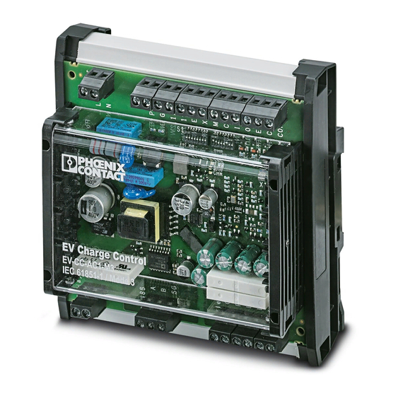
- Page 1 EV Charge Control Basic Installing and starting up the charging controller User manual...
- Page 2 Installing and starting up the charging controller UM EN EV-CC-AC1-M3-C, Revision 05 2021-03-24 This user manual is valid for: Designation Version Order No. EV-CC-AC1-M3-CBC-SER-HS 1622452 EV-CC-AC1-M3-CBC-SER-PCB 1622453 EV-CC-AC1-M3-CC-SER-HS 1622459 EV-CC-AC1-M3-CC-SER-PCB 1622460 PHOENIX CONTACT GmbH & Co. KG • Flachsmarktstraße 8 • 32825 Blomberg • Germany phoenixcontact.com...
-
Page 3: Table Of Contents
Charging cable connection (case B and C) ............25 Vehicle status (status A - F) ................. 26 Typical charging sequence.................. 27 Simplified charging sequence................29 Activation mode....................30 Wiring the outputs and inputs ....................31 Outputs........................ 31 Inputs........................33 3 / 68 PHOENIX CONTACT 106377_en_05... - Page 4 EV Charge Control Basic Connection examples ......................35 Charging enabled with local release..............35 Charging enabled with local release and status indication via external LEDs ..36 Charging enabled with local release and charging current reduction....37 Charging enabled with local release and locking ..........38 Charging enabled via Modbus................
-
Page 5: Properties Of The Charging Controller
Properties of the charging controller Properties of the charging controller The EV Charge Control Basic charging controller is exclusively used to control and monitor the charging of electric vehicles on the 3-phase AC power grid in charging mode 3 accord- ing to IEC 61851-1, AC level 2 according to SAE J1772, and mode 3 according to GB/T 18487.1. -
Page 6: Ordering Data
EV Charge Control Basic Ordering data Charging controller Description Type Order No. Pcs. / Pkt. Charging controller for connection of case B and C, with EV-CC-AC1-M3-CBC-SER- 1622452 housing for DIN rail mounting Charging controller for connection of case B and C, as... - Page 7 0.25 mm ... 1.5 mm tic sleeve Stranded conductor cross section with ferrule with plastic 0.25 mm ... 1.5 mm sleeve Conductor cross section AWG 24 ... 14 AWG/kcmil 7 / 68 PHOENIX CONTACT 106377_en_04...
- Page 8 EV Charge Control Basic Order number 1622452 1622453 1622459 1622460 EV-CC-AC1-M3- CBC-SER-HS CBC-SER-PCB CC-SER-HS CC-SER-PCB AWG according to UL/CUL AWG 30 ... 12 Conformance/approvals CE-compliant √ Low-voltage directive 2006/95/EC Safety test IEC 61010-1 Function test IEC 61851-1, Appendix A Air clearances and creepage...
-
Page 9: Connections, Indicators, Configuration Switches
Error or status E or status F Charging Digital output, can be configured Default: set when the charging contactor is actuated Connect Digital output, can be configured Default: set when a vehicle is connected to the charging controller 9 / 68 PHOENIX CONTACT 106377_en_04... - Page 10 EV Charge Control Basic Table 2-1 Connections [...] No. Name Meaning Description Locking Control of the locking actuator † Lock Detection Digital input, for connecting the locking confirmation, can be configured † Proximity Plug Test signal Current carrying capacity of the connected †...
-
Page 11: Diagnostic And Status Indicators
Error Error Flashing Errors that originate at the vehicle or charging cable (1 Hz) Charging Blue Charging contactor closed Flashing Vehicle connected, charging current ready, PWM signal switched (1 Hz) on, charging contactor open 11 / 68 PHOENIX CONTACT 106377_en_04... -
Page 12: Configuration Switches S1 + S2
EV Charge Control Basic Configuration switches S1 + S2 WARNING: Dangerous contact voltage Electrical shock from unprotected live parts. Only set the configuration switches when the device is disconnected from the mains. Figure 2-3 Configuration switches S1 + S2 12 / 68... - Page 13 1, 1, 1, 1, 0 = Modbus address 30 1, 1, 1, 1, 1 = reserved 7 + 8 Reserved for future expansions Not for EV-CC-AC1-M3-CC-... For additional information, please refer to “Flow charts for the charging process” on page 13 / 68 PHOENIX CONTACT 106377_en_04...
- Page 14 EV Charge Control Basic 14 / 68 PHOENIX CONTACT 106377_en_04...
-
Page 15: For Your Safety
The device contains components that can be damaged or destroyed by electrostatic dis- charge. When handling the device, observe the necessary safety precautions against elec- trostatic discharge (ESD) according to IEC 61340-5-1. Observe these safety precautions, specifically for device EV-CC-...-PCB. 15 / 68 PHOENIX CONTACT 106377_en_04... -
Page 16: Maintenance And Disposal
EV Charge Control Basic Operation in a clean and dry environment only The degree of protection of the device is designed for an environment with a maximum pol- lution degree of 2 according to IEC 60664-1. Product Degree of protection EV-CC-...-PCB... -
Page 17: Startup
The device contains components that can be damaged or destroyed by electrostatic discharge. When handling the device, observe the necessary safety precautions against electrostatic discharge (ESD) in accordance with IEC 61340-5-1. Dimensions Figure 4-1 Dimensions of EV-CC-...-PCB Ø4 20,6 Figure 4-2 Dimensions of EV-CC-...-HS 17 / 68 PHOENIX CONTACT 106377_en_04... -
Page 18: Mounting The Pcb (Ev-Cc
EV Charge Control Basic Mounting the PCB (EV-CC-...-PCB only) WARNING: Dangerous contact voltage Electrical shock from unprotected live parts. Only mount the PCB when the device is disconnected from the mains. Only operate the device in a charging station housing that corresponds to the applica- ble requirements for charging stations. -
Page 19: Fitting The Covering Hood
For assembly, proceed as follows: Fit the covering hood so that it engages with a click. To latch the lateral elements, push the four safety elements into the PCB. Recommended tool: prong ø 3 mm 19 / 68 PHOENIX CONTACT 106377_en_04... -
Page 20: Mounting On The Din Rail
EV Charge Control Basic Mounting on the DIN rail Figure 4-6 Mounting/removal The device can be mounted in any position on the DIN rail. Mounting on a DIN rail (A) Place the device onto the DIN rail from above. Push the front of the device toward the mounting surface until it engages with a click. -
Page 21: Connecting The Supply Voltage
C1 - C2. The charging contactor is connected using a relay that can be loaded up to 250 V/6 A, maximum. For the relevant connection examples, please refer to Figure 7-1 on page 21 / 68 PHOENIX CONTACT 106377_en_04... -
Page 22: Locking The Infrastructure Socket Outlet (Ev-Cc
Modbus. For the relevant parameters, please refer to Section 9, “Modbus description”. For connection examples of an Infrastructure Socket Outlets from Phoenix Contact, please refer toFigure 7-1 on page Configuration The charging controller is basically configured using configuration switches S1 and S2. -
Page 23: Signal Contacts And Charging Sequences
According to GB/T 18487.1, a charging connector is detected when S1/DIP 7 is set to ON, and a resistance value of 0 Ω is detected on the Proximity Plug. According to GB/T 18487.1, coding of the current carrying capacity on the charging station is not provided. 23 / 68 PHOENIX CONTACT 106377_en_04... -
Page 24: Control Pilot Signal (Cp)
EV Charge Control Basic Control Pilot signal (CP) Figure 5-2 Control Pilot wiring Control Pilot 12 V Via the CP signal (Control Pilot), the device specifies the permissible charging current value to the vehicle which is coded as a PWM signal. The vehicle indicates the current vehicle sta- tus via the voltage value Va. -
Page 25: Charging Cable Connection (Case B And C)
Observe the connection methods according to IEC 61851-1 for each product: – Charging controller for connection of case B and case C for EV-CC-AC1-M3- CBC-... products – Charging controller for connection of case C for EV-CC-AC1-M3-CC-... product 25 / 68 PHOENIX CONTACT 106377_en_04... -
Page 26: Vehicle Status (Status A - F)
EVSE not available available Switch S2 (see “Control Pilot wiring” on page † Va = measured voltage in the EV Charge Control Basic ‡ Vb = measured voltage in the vehicle EVSE = Electric Vehicle Supply Equipment (charging station) ††... -
Page 27: Typical Charging Sequence
Charging in status D can be supported using a configuration. When configuring a digital output for the “status D” event, an exter- nal ventilation can be connected. This ventilation is not monitored. The ventilation must be monitored using suitable measures. 27 / 68 PHOENIX CONTACT 106377_en_04... - Page 28 EV Charge Control Basic Table 5-4 Charging sequence according to the vehicle status Vehicle Status Description Signal CP status Charging stopped The charging process can be aborted via the charging station or via the vehicle. Switching off via the charging station: The charging station switches off the PWM signal and indicates the end of the charging process.
-
Page 29: Simplified Charging Sequence
10 A. Resistance value R corresponds to the parallel connection of resistors R2 and R3 from “Control Pilot wiring” on page Status C or D can be reached with the simplified charging sequence. 29 / 68 PHOENIX CONTACT 106377_en_04... -
Page 30: Activation Mode
EV Charge Control Basic Activation mode Figure 5-7 Typical curve of signal CP in activation mode -12V 30 s If the connected vehicle switches from status B1 (9 V DC) to status B2 (9 V PWM) and the vehicle does not enter status C or D within 30 seconds, the charging controller simulates the disconnection of the vehicle from the charging station. -
Page 31: Wiring The Outputs And Inputs
The outputs are not short circuit proof or protected against overload. The function of the outputs can be configured. For details, please refer to the Modbus register description in Section Figure 6-1 Transistor wiring of the outputs V 12a 31 / 68 PHOENIX CONTACT 106377_en_04... -
Page 32: Output Circuit With Lamps
EV Charge Control Basic Connection of high-power loads (e.g., lamps) – The output stages are supplied with the required voltage of 5 V DC to 30 V DC maxi- mum via voltage input 12Va. – In status 0 (OFF), the outputs are connected to GND and in status 1 (ON,) they are con- nected to the potential of 12Va. -
Page 33: Inputs
12 V outputs. Here too, GND is used as the common reference point. Figure 6-5 Inputs at switches with internal supply Figure 6-6 Inputs at switches with external supply 12 V DC 33 / 68 PHOENIX CONTACT 106377_en_04... - Page 34 EV Charge Control Basic 34 / 68 PHOENIX CONTACT 106377_en_04...
-
Page 35: Connection Examples
The charging process starts if the locking feedback is available, switch k1 is closed, and status C is present. Figure 7-1 Connection example 1 EV-CC-AC1-M3-CBC-..., connection of case B 20 A 32 A 230 V L, L1-L3 EV-T2M3SE12-3AC... 35 / 68 PHOENIX CONTACT 106377_en_04... -
Page 36: Charging Enabled With Local Release And Status Indication Via External Leds
EV Charge Control Basic Charging enabled with local release and status in- dication via external LEDs S1/DIP 1 = ON Charging station with Vehicle Connector Status indication via external LEDs The charging process starts if switch k1 is closed and status C is present. -
Page 37: Charging Enabled With Local Release And Charging Current Reduction
If switch k2 is closed, the charging current (PWM signal) is reduced during this time (see Table 2-3 on page 13). Figure 7-3 Connection example 3 EV-CC-AC1-M3-CBC-..., connection of case B 32 A 230 V L, L1-L3 EV-T2M3SE12-3AC... 37 / 68 PHOENIX CONTACT 106377_en_04... -
Page 38: Charging Enabled With Local Release And Locking
EV Charge Control Basic Charging enabled with local release and locking S1/DIP 1 = OFF Charging station with Infrastructure Socket Outlet S1/DIP 3 = ON Connection locking upon signal at digital input ML Locking is carried out if switch k1 is closed and a charging connector is detected. -
Page 39: Charging Enabled Via Modbus
MAC Addr.: xx.xx.xx.xx AUTOMATIONWORX MRESET SG B A STOP RUN / PROG RESET 230 V L, L1-L3 EV-T2M3SE12-3AC... Please observe that the RS-485 cable must be terminated at one point with a 120 Ω resistor. 39 / 68 PHOENIX CONTACT 106377_en_04... -
Page 40: Charging Current Control Via Analog Ccr Signal
EV Charge Control Basic Charging current control via analog CCR signal The digital CCR input can be reconfigured to function as an analog input (see Table 9-2 “Register assignment”). S1/DIP 1 = OFF Charging station with Infrastructure Socket Outlet S1/DIP 5 = ON Charging current preset to 32 A Locking is carried out if a vehicle is detected. - Page 41 Update time of charging current output Table 7-1 shows an example of how the Modbus registers can be configured in order to con- trol the charging current via the CCR function at the analog output. 41 / 68 PHOENIX CONTACT 106377_en_04...
-
Page 42: Charging Contactor Monitoring
EV Charge Control Basic Charging contactor monitoring S1/DIP 1 = OFF Charging station with Infrastructure Socket Outlet Locking is carried out if a vehicle is detected. The charging process starts if the locking feedback is available and status C is present. - Page 43 To do so, one of the OUT, ERR, CHG, or CON outputs must be config- ured to value “35” via the associated registers 5500 to 5503 (value “35” = “Charging contac- tor monitoring triggered” (see Table 9-3). 43 / 68 PHOENIX CONTACT 106377_en_04...
-
Page 44: Connection To A Residual Current Monitoring Device
EV Charge Control Basic Connection to a residual current monitoring de- vice As of firmware version 1.2.0 S1/DIP 1 = OFF Charging station with Infrastructure Socket Outlet S1/DIP 2 = OFF The XR input is evaluated in a modified way according to Modbus register 4011 (see Table 7-3 on page 45). - Page 45 The device test can also be carried out manually or from a higher-level controller. Table 7-4 Device configuration example for connecting the EV-RCM residual current monitoring device Address Value Unit Explanation 5500 – Triggering of EV-RCM device test activated at output OUT 45 / 68 PHOENIX CONTACT 106377_en_04...
- Page 46 EV Charge Control Basic 46 / 68 PHOENIX CONTACT 106377_en_04...
-
Page 47: Flow Charts For The Charging Process
S1/DIP 1 = OFF 1 2 3 4 5 S1/DIP 5 = OFF (20 A) 32 A S1/DIP 6 = ON EV Charge Control Basic EV Charge Control basic IEC 61 Mode 3 1 2 3 4 5 S1/DIP 5 = ON... -
Page 48: Charging Sequence 2
EV Charge Control Basic Charging sequence 2 Charging sequence according to connection example 7.2, “Charging enabled with local release and status indication via external LEDs” Figure 8-2 Charging sequence 2 S1/DIP 1 = ON EV Charge Control Basic EV Charge Control basic... -
Page 49: Charging Sequence 3
Figure 8-3 Charging sequence 3 32 A S1/DIP 1 = OFF S1/DIP 5 = ON EV Charge Control Basic EV Charge Control basic (32 A) 1 2 3 4 5 S1/DIP 6 = OFF IEC 61... -
Page 50: Charging Sequence 4
EV Charge Control Basic Charging sequence 4 Charging sequence according to connection example 7.4, “Charging enabled with local release and locking” Figure 8-4 Charging sequence 4 S1/DIP 1 = OFF S1/DIP 3 = ON EV Charge Control Basic EV Charge Control basic... -
Page 51: Charging Sequence 5
The charging sequence shows an availability test via the XR input and the charging enabled status via the EN input. Figure 8-5 Charging sequence 5 S1/DIP 1 = OFF S1/DIP 2 = ON EV Charge Control Basic EV Charge Control basic 1 2 3 4 5 IEC 61 Mode 3 -12V PP[ Ω... -
Page 52: Charging Sequence 6
EV Charge Control Basic Charging sequence 6 Charging sequence according to connection example 7.6, “Charging current control via analog CCR signal”. Figure 8-6 Charging sequence 6 32 A S1/DIP 1 = OFF S1/DIP 5 = ON EV Charge Control Basic... -
Page 53: Modbus Description
Modbus register types Modbus/RTU supports three register types which are used as follows. Table 9-1 Modbus registers Modbus register type Value Access Input 16 bits Read Holding 16 bits Read/write Coils 1 bit Read/write 53 / 68 PHOENIX CONTACT 106377_en_04... -
Page 54: Register Assignment
EV Charge Control Basic Register assignment The following table shows how the device registers are assigned to addresses that can be accessed via Modbus/RTU. Unless otherwise specified, the numerical values are decimal values. Table 9-2 Register assignment Type Address Value... - Page 55 1: Available if XR = ON, status F if XR = OFF (Default, if S1/DIP 2 = ON) 2: Available if value 1 is written to register 20001. Status F if value 0 is written to register 20001. 55 / 68 PHOENIX CONTACT 106377_en_04...
- Page 56 EV Charge Control Basic Table 9-2 Register assignment Type Address Value Access Memory Function Coding Hold- 4002 16 bits Read/write Retentive Activating the locking function Integer Charging connector in the In- If S1/DIP 3 = OFF: frastructure Socket Outlet 0: Locking is performed automat-...
- Page 57 4013 16 bits Read/write Retentive Threshold value for switching Integer in mV off (0 A) or switching on (6 A) Default = 0 mV the charging process, with an- alog evaluation of input CCR 57 / 68 PHOENIX CONTACT 106377_en_04...
- Page 58 EV Charge Control Basic Table 9-2 Register assignment Type Address Value Access Memory Function Coding Hold- 4014 16 bits Read/write Retentive Threshold value for maximum Integer in mV charging current (S1/DIP Default = 10,000 mV switches 5 + 6), with analog...
- Page 59 Dimming the on-board LED Integer, 1 x 16 bits Percentage, pulse duty factor 0% … 100% 7503 16 bits Read/write Retentive Dimming the on-board LED Integer, 1 x 16 bits Percentage, pulse duty factor 0% … 100% 59 / 68 PHOENIX CONTACT 106377_en_04...
- Page 60 EV Charge Control Basic Table 9-2 Register assignment Type Address Value Access Memory Function Coding Coils 20000 1 bit Read/write Volatile Enabling the charging process 1 bit Switching on the PWM signal 0 = charging process not enabled if all other conditions required 1 = charging process enabled are met.
- Page 61 Status of digital inputs 16 bits Bit 0 – bit 4: EN, XR, ML, CCR, 24005 16 bits Read Volatile Status of digital outputs 16 bits Bit 0 – bit 3: OUT, ERR, CHG, 61 / 68 PHOENIX CONTACT 106377_en_04...
- Page 62 EV Charge Control Basic Table 9-2 Register assignment Type Address Value Access Memory Function Coding Hold- 24017 16 bits Read Volatile Minutes counter and seconds Integer, 2 x 8 bits counter in status C and D, mm:ss reset condition via status A...
-
Page 63: Function Assignment Of Output Registers
Charging controller has detected a 20 A connector at PP Charging controller has detected a 32 A connector at PP Charging controller has detected a 63 A connector at PP Charging controller has detected a 13 A or 20 A connector at PP 63 / 68 PHOENIX CONTACT 106377_en_04... - Page 64 EV Charge Control Basic Table 9-3 Function assignment of output registers for the digital outputs Value Function Charging controller has detected a 13 A or 20 A connector at PP Insufficient current carrying capacity of the charging cable Charging controller switches the charging contactor ON...
-
Page 65: Appendixes
Output circuit with LEDs ..............32 Figure 6-4: Assignment of the logic states to the voltages ........33 Figure 6-5: Inputs at switches with internal supply ..........33 Figure 6-6: Inputs at switches with external supply ..........33 65 / 68 PHOENIX CONTACT 106377_en_05... - Page 66 EV Charge Control Basic Section 7 Figure 7-1: Connection example 1 ................ 35 Figure 7-2: Connection example 2 ................ 36 Figure 7-3: Connection example 3 ................ 37 Figure 7-4: Connection example 4 ................ 38 Figure 7-5: Connection example 5 ................ 39 Figure 7-6: Connection example 6 ................
- Page 67 The receipt of technical documentation (in particular user documentation) does not constitute any further duty on the part of Phoenix Contact to furnish information on modifications to products and/or technical documentation. You are responsible to verify the suitability and intended use of the products in your specific application, in particular with regard to observing the applicable standards and regulations.
- Page 68 Should you have any suggestions or recommendations for improvement of the contents and layout of our manuals, please send your comments to: tecdoc@phoenixcontact.com 68 / 68 PHOENIX CONTACT GmbH & Co. KG • Flachsmarktstraße 8 • 32825 Blomberg • Germany phoenixcontact.com...
- Page 70 PHOENIX CONTACT GmbH & Co. KG Flachsmarktstraße 8 32825 Blomberg, Germany Phone: +49 5235 3-00 Fax: +49 5235 3-41200 E-mail: info@phoenixcontact.com phoenixcontact.com...
Need help?
Do you have a question about the EV Charge Control Basic and is the answer not in the manual?
Questions and answers