Phoenix Contact AXC 1050, 2700988 - Controller Installation Notes For Electricians
- User manual (162 pages)
Advertisement
- 1 Safety notes
- 2 Components of the controller
- 3 Structure of an Axioline F station
- 4 Installing the bus base module
- 5 Snapping on the controller
- 6 Removing the controller
- 7 Connecting Ethernet
- 8 Removing the supply connector
- 9 Inserting supply connector
- 10 Connecting cables
- 11 Removing the cable
- 12 Terminal point assignment
- 13 Inserting the parameterization memory
- 14 Removing the parameterization memory
- 15 Programming interface PROG (USB)
- 16 Display elements
- 17 Documents / Resources
Safety notes

NOTE:
Observe the necessary safety precautions when handling components that are vulnerable to electrostatic discharge (EN 61340-5-1 and IEC 61340-5-1).

Also strictly observe the additional information in the user manual and the Axioline F system manual at phoenixcontact.net/products.

The controller is automatically grounded (FE) when it is snapped onto a grounded DIN rail.
The rear of the controller provides two FE springs that contact the DIN rail when the controller is placed on the DIN rail.
Before working on the station, controller or module, disconnect the station from the power!
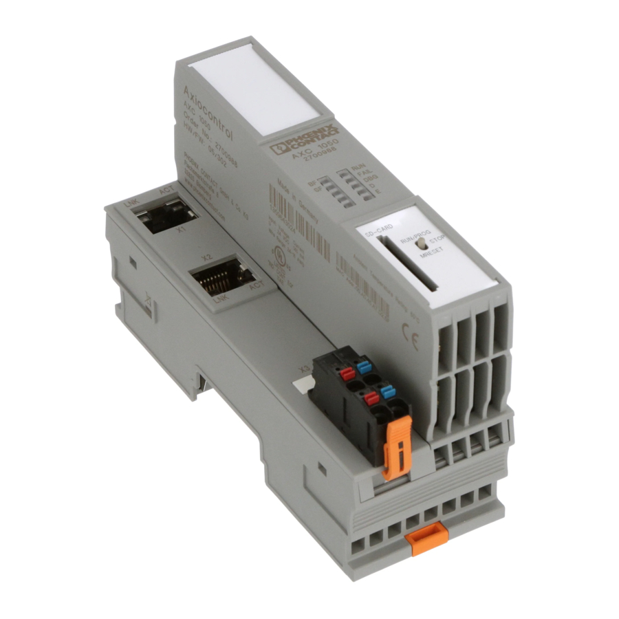
Components of the controller

- Bus base module
- Reset button
- Programming interface
- Electronics module
- Ethernet interfaces (X1, X2)
- FE tabs (X3); 2.8 mm for optional connection to functional earth ground
- Connector for connecting the supply voltage
- Slot for the parameterization memory
- Mode selector switch
- Diagnostic and status indicators
Structure of an Axioline F station

- DIN rail
- End clamp (e.g., CLIPFIX 35-5, Order No. 3022276)
- Controller AXC 1050
- Input/output modules corresponding to the application
- Bus base module
Installing the bus base module

First install the bus base module for the controller and all bus base modules necessary for the station onto the DIN rail (A). Push each subsequent bus base module into the connection of the previous bus base module (B).
Snapping on the controller

Place the controller vertically on the first bus base module and the DIN rail until it snaps into place with a click.
Make sure that the device connector for the bus base connection is situated above the corresponding socket on the bus base module.
Removing the controller

Insert a suitable tool, (e.g., flat-bladed screwdriver) into the upper and lower snap-on mechanism (base latches) of the controller one after the other and release it (A). The base latches are locked in place in the open position.
Remove the controller perpendicular to the DIN rail (B).
Connecting Ethernet

Connect the Ethernet network to the RJ45 socket.
Removing the supply connector

Release the locking latch (A), tip the connector slightly upwards (B), and remove it from the module (C).
Inserting supply connector

Place the connector vertically in its position and press firmly. Make sure that the latching lock snaps in.
Connecting cables
Strip 8 mm of insulation from the end of the wire. If required, fit a ferrule to the wire (see user manual).
Rigid wire/ferrule

Insert the wire into the terminal point. The wire is clamped automatically.
Flexible wire

Open the spring by pressing a screwdriver onto the spring lever (A). Insert the wire in the terminal point (B). Remove the screwdriver to secure the wire.
Recommended: flat-bladed screwdriver, 2.5 mm blade width (e. g., SZS 0.4x2.5 Order No. 1205037)
Removing the cable

Open the spring by pressing a screwdriver onto the spring lever (A).
Remove the cable (B).
Terminal point assignment

| Terminal point | Color | Assignment |
| a1, a2 | Red | 24 V DC (UL) |
| b1, b2 | Blue | GND |
UL Supply of the logic voltage (internally jumpered)
GND Reference potential of the supply voltage (internally jumpered)
Inserting the parameterization memory

Lightly push the parameterization memory into the slot until it naps into the holder.
Removing the parameterization memory

Lightly push the parameterization memory far enough into the slot until the snap-on mechanism releases and partially ejects it from the slot. Remove the parameterization memory.
Programming interface PROG (USB)
")
A PC with the PC Worx / PC Worx Express software can be connected via the programming interface.
The programming interface (2) is located beneath the labeling field (1) on the controller.

You can order a suitable USB cable with the designation CAB-USB A/MICRO USB B/2,0M (Order No. 2701626).
Display elements

| PLC | ||
| RUN | Green | Controller state/controller in RUN state |
| FAIL | Red | Error |
| DBG | Yellow | Debug mode (troubleshooting) |
| PWR | ||
| UL | Green | ULogic |
| AXC | ||
| D | Red/yellow/green Axioline F diagnostics | |
| E | Red/yellow | Axioline F device: Error/Warning |
| PN | ||
| BF | Red | Communication error (BusFail) |
| SF | Red | System error (SystemFail) |
| ETH | ||
| LNK | Green | Connection active |
| ACT | Yellow | Data transmission active |

Documents / ResourcesDownload manual
Here you can download full pdf version of manual, it may contain additional safety instructions, warranty information, FCC rules, etc.
Download Phoenix Contact AXC 1050, 2700988 - Controller Installation Notes For Electricians
Advertisement


Need help?
Do you have a question about the AXC 1050 and is the answer not in the manual?
Questions and answers