
Related Manuals for Phoenix Contact AXC F 1152


Summary of Contents for Phoenix Contact AXC F 1152
- Page 1 Installing, starting up, and operating the AXC F 1152, AXC F 2152 and AXC F 3152 controllers User manual...
-
Page 2: Axc F 2152
User manual Installing, starting up, and operating the AXC F 1152, AXC F 2152 and AXC F 3152 controllers UM EN AXC F X152, Revision 08 2020-09-30 This user manual is valid for: Designation As of version (HW) As of version (FW) Order No. -
Page 3: Table Of Contents
Connection and operating elements ............ 22 3.8.2 Printing ....................24 Diagnostic and status indicators ................26 3.10 Mode selector switch (AXC F 3152) ..............30 3.11 Reset button ......................31 3.12 Parameterization memory..................33 3.13 SD card (optional)....................33 3 / 112 107708_en_08 PHOENIX CONTACT... - Page 4 Transferring variable values to PROFICLOUD .................64 System variables and status information ..................65 General information ..................... 65 Data structures ....................65 System time......................67 Power supplies ....................67 TCP_SOCKET, UDP_SOCKET, and TLS_SOCKET function blocks....67 4 / 112 PHOENIX CONTACT 107708_en_08...
- Page 5 14 Ordering data and technical data .....................91 14.1 Ordering data ...................... 91 14.2 Overview of documentation ................. 92 14.3 Technical data of the AXC F 1152 and AXC F 2152 ..........93 14.4 AXC F 3152 technical data .................. 98 5 / 112 107708_en_08 PHOENIX CONTACT...
- Page 6 Shell commands for controlling the firmware ............. 102 Replacing the HTTPS certificate................ 102 Use of the AXC F 2152 controller under extreme ambient conditions....103 Appendix for document lists....................104 List of figures ..................... 104 List of tables ...................... 107 Index........................109 6 / 112 PHOENIX CONTACT 107708_en_08...
-
Page 7: For Your Safety
– Qualified application programmers and software engineers. The users must be familiar with the relevant safety concepts of automation technology as well as applicable stan- dards and other regulations. 7 / 112 107708_en_08 PHOENIX CONTACT... -
Page 8: Field Of Application Of The Product
1.3.1 Intended use The AXC F 1152 and AXC F 2152 controllers are modular small-scale controllers. The AXC F 3152 is a modular controller that can be used for smaller and medium-sized applica- tions. The devices comply with the IP20 protection class and are designed for use in closed control cabinets or control boxes (terminal boxes) with an IP54 degree of protection or higher. -
Page 9: Security In The Network
Phoenix Contact GmbH & Co. KG, Flachsmarktstraße 8, 32825 Blomberg, Germany in accordance with §§ 15 ff AktG (German Stock Corporation Act), hereinafter collectively referred to as “Phoenix Contact”, from all third-party claims made due to improper use. For the protection of networks for remote maintenance via VPN, Phoenix Contact offers the mGuard product range of security appliances, a description of which you will find in the latest Phoenix Contact catalog (phoenixcontact.net/products). -
Page 10: Ul Warning Notes
AXC F X152 UL warning notes Valid for AXC F 1152 and AXC F 2152 If the device is not used in the specified manner, the protection provided by the device may be impaired. SELV - Limited energy according UL/IEC/EN 61010-1 or NEC Class 2... -
Page 11: Temperature Derating Of The Axc F 2152 Depending On The Alti
Temperature derating of the AXC F 2152 depending on the altitude Altitude (above sea level) Maximum ambient temperature (supply via bus base module) Up to 2000 m 55°C 2000 m ... 3000 m 49°C 11 / 112 107708_en_08 PHOENIX CONTACT... -
Page 12: Transport, Storage, And Unpacking
NOTE: Property damage due to noncompliance with ESD notes If the ESD notes are not observed during unpacking and packaging, the device may be- come damaged. • Observe the ESD notes during unpacking and packaging. 12 / 112 PHOENIX CONTACT 107708_en_08... - Page 13 Damaged packaging is an indicator of potential damage to the device that may have oc- curred during transport. This could result in a malfunction. • Submit claims for any transport damage immediately, and inform Phoenix Contact or your supplier as well as the shipping company without delay. •...
-
Page 14: Description Of The Controllers
, etc.). These programs or program parts must then be imported into PLCnext Engineer as a library. Integrated Ethernet The AXC F 1152 and AXC F 2152 controllers feature two switched Ethernet interfaces for interfaces TCP/IP / UDP/IP communication within the Ethernet network. -
Page 15: Axioline F Extension Module
AXC F 3152 using the supplied AXC BS L 30 bus base module. Connection of the left- alignable AXC F XT ETH 1TX Ethernet interface is not supported yet. – Axioline F extension modules cannot be aligned to the left of the AXC F 1152. The following left-alignable Axioline F extension modules are currently available: –... - Page 16 Phoenix Contact controllers of the PLCnext Control product family. If you format the SD card, certain information on the SD card that is required for use with Phoenix Contact de- vices will be lost. After formatting, you can no longer use the SD card to operate the con- troller.
-
Page 17: Licensing Information Regarding Open-Source Software
You can request the source code of these software components in the form of a CD or DVD- ROM for a processing fee of 50 euros within three years after delivery of the controller. To do so, contact the Phoenix Contact After Sales Service in writing at the following ad- dress: PHOENIX CONTACT GmbH &... -
Page 18: Using Sftp To Access The File System
MRESET PLCnext Technology Designed by PHOENIX CONTACT BF-C BF-C FAIL BOOT BF-C BF-C FAIL BOOT password: 12345678 AXC F 1152 and AXC F 2152 AXC F 3152 Figure 3-2 Administrator password on the controller 18 / 112 PHOENIX CONTACT 107708_en_08... -
Page 19: Firewall
(1 A at an ambient temperature ≤55°C). If the current consumption exceeds the maximum current, use the AXL F PWR 1H power module. Ethernet Figure 3-3 Example: Axioline F station with AXC F 2152 controller 19 / 112 107708_en_08 PHOENIX CONTACT... -
Page 20: The Controller As A Profinet Controller In A Profinet Network
Figure 3-4 Example: AXC F 3152 controller as PROFINETcontroller Key: PROFINET controller (AXC F 1152, AXC F 2152 or AXC F 3152) PROFINET device and switch (in the example: controller with connected Axioline F I/O modules) For additional information on how to integrate the controller as a PROFINET controller into a PROFINET network, please refer to the PLCnext Engineer online help. -
Page 21: The Controller As A Profinet Device In A Profinet Network
PROFINET controller (in the example: RFC 4072S) Managed switch (in the example: FL SWITCH SMCS ...) PROFINET device (AXC F 1152, AXC F 2152 or AXC F 3152) For additional information on how to integrate the controller as a PROFINET device into a PROFINET network, please refer to the PLCnext Engineer online help. -
Page 22: Components Of The Controller
3.8.1 Connection and operating elements AXC F 1152 and AXC F 2152 Figure 3-6 Connection and operating elements of the AXC F 1152 and AXC F 2152 controllers The controller consists of the following components: Bus base module Electronics module... -
Page 23: Connection And Operating Elements Of The Axc F 3152 Control
Please refer to the ordering data in Section “Ordering data” on page Mode selector switch Service interface (X4) Ethernet interfaces (X1, X2, X3) Supply connector (connector for connecting the supply voltage (communications volt- age U 23 / 112 107708_en_08 PHOENIX CONTACT... -
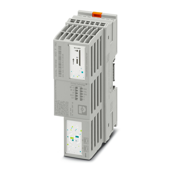
Page 24: Printing
AXC F X152 3.8.2 Printing AXC F 1152 and AXC F 2152 controller printing Order number and order designation SD-CARD MAC address QR code for UUID Administrator password QR code for connecting to the PLC- next Community PLCnext T echnology... - Page 25 In the PLCnext Community, you will find: – Information on PLCnext Technology – Information on PLCnext Engineer – Information on programming the controller with C++ – Operating instructions – Tutorials – Example projects – FAQs 25 / 112 107708_en_08 PHOENIX CONTACT...
-
Page 26: Diagnostic And Status Indicators
The diagnostic and status indicators are used for quick local error diagnostics. BF-C PN/AXC/ BF-D FAIL BOOT BF-C BF-D FAIL BOOT PN/AXC/ AXC F 1152 and AXC F 2152 AXC F 3152 Figure 3-10 Diagnostic and status indicators Table 3-1 Controller diagnostic and status indicators Desig- Color Meaning State Description... - Page 27 (troubleshooting) The status of the RUN LED is not affected. Device firmware is faulty. Device firmware Flashing Device firmware is being loaded (boot process). BOOT loading status (2 Hz) Device firmware running. 27 / 112 107708_en_08 PHOENIX CONTACT...
- Page 28 Power down: Local bus device is in (power) reset Yellow on I/O warning at a local bus device Yel- Error/warning low/red Red on I/O error at a local bus device 28 / 112 PHOENIX CONTACT 107708_en_08...
- Page 29 On/flashing sending or receiving data. Please note: On the AXC F 1152, the EXT LED is without function as Axioline F extension modules cannot be aligned to the left. Special case: firmware update During a firmware update, the RUN LED first flashes, and then stops. Upon a successful controller restart, the RUN LED lights up again permanently.
-
Page 30: Mode Selector Switch (Axc F 3152)
Hold the mode selector switch in the MRESET position for three seconds. • Release the mode selector switch for less than three seconds. • Hold the mode selector switch in the MRESET position for three seconds. 30 / 112 PHOENIX CONTACT 107708_en_08... -
Page 31: Reset Button
Description of the controllers 3.11 Reset button AXC F 1152 and AXC F 2152 AXC F 3152 Figure 3-12 Reset button (1) The reset button on the controller can only be operated with a pointed object, such as a pin, and is therefore protected against accidental activation. -
Page 32: Sequence When Resetting To Default Setting Type 1, And Led Indicators
Release the reset button. The controller is reset to default setting type 2. BF-C FAIL BF-D FAIL 30 s BOOT Power on Reset Figure 3-14 Sequence when resetting to default setting type 2, and LED indicators 32 / 112 PHOENIX CONTACT 107708_en_08... -
Page 33: Parameterization Memory
On the internal controller parameterization memory, the following data quantities are avail- able for user-specific data and the overlay file system: – 512 Mbyte on the AXC F 1152 and AXC F 2152 controllers – 1 GB on the AXC F 3152 controller 3.13... - Page 34 Phoenix Contact controllers of the PLCnext Control product family. If you format the SD card, certain information on the SD card that is required for use with Phoenix Contact de- vices will be lost. After formatting, you can no longer use the SD card to operate the con- troller.
- Page 35 Section “Diagnostic and status indicators” on page 26 for the LED blink codes in the event of unauthorized removal of the SD card during operation. • Only use an SD card provided by Phoenix Contact, see Section “Ordering data” on page Please note: The SD card can be read with a conventional SD card reader at any time.
-
Page 36: Internal Basic Circuit Diagram
LNK ACT Reset μC Extension Local Bus 3.3 V 24 V 24 V Figure 3-15 Internal basic circuit diagram for AXC F 1152 and AXC F 2152 Key: μC Microprocessor Transmitter Service interface Reset button Real-time clock RJ45 3.3 V... -
Page 37: Internal Basic Circuit Diagram Axc F 3152
Chipset Chipset Local bus Extension Left-aligned Axioline F extension modules Axioline F local bus Processor Fan connection The colored areas in the basic circuit diagram represent electrically isolated areas: Logic Ethernet interface Functional ground 37 / 112 107708_en_08 PHOENIX CONTACT... -
Page 38: Communication Paths
AXC F X152 3.15 Communication paths The following communication paths are available on the controllers: AXC F 1152 and AXC F 2152 2 x Ethernet X1/X2: 10/100 BASE-T(X) (switched internally) Service interface No function at present Figure 3-17 Communication paths: (1) Ethernet, (2) service interface... -
Page 39: Ethernet
Table 3-3 Terminal point assignment of the supply connector Terminal point Color Assignment a1, a2 24 V DC (U b1, b2 Blue Key: Communications voltage feed-in (bridged internally) Supply voltage reference potential (bridged internally) 39 / 112 107708_en_08 PHOENIX CONTACT... -
Page 40: Bus Base Module
Bus base modules carry the communications voltage and the bus signals from the controller module through the Axioline F station (local bus). The AXL BS BK bus base module is supplied with the AXC F 1152 and AXC F 2152 controllers. Figure 3-20 Structure of the AXL BS BK bus base module... -
Page 41: Structure Of The Axc Bs L 30 Bus Base Module
Connection to the bus base module of a left-alignable Axioline F extension module Bus base module Connection of the extension bus to the controller Connection of the local bus to the controller Connection to the bus base module of the local bus 41 / 112 107708_en_08 PHOENIX CONTACT... -
Page 42: Mounting Hardware
DIN rail. There are two FE springs on the back of the controller that make contact with the DIN rail when the controller is placed on the DIN rail. Figure 4-1 Placing the module vertically 42 / 112 PHOENIX CONTACT 107708_en_08... -
Page 43: Basic Information
Mount end brackets on both sides of the Axioline F station. The end brackets ensure that the Axioline F station is correctly mounted. End brackets secure the station on both sides and keep it from moving from side to side on the DIN rail. Phoenix Contact recommends the following end brackets:... -
Page 44: Example: Axc F 2152 In Horizontal (A) And Vertical (B) Installa
Figure 4-2 Example: AXC F 2152 in horizontal (A) and vertical (B) installation position Note the ambient temperatures and any other special features (e.g., derating) specified in the device/module-specific documentation for the Axioline F devices. 44 / 112 PHOENIX CONTACT 107708_en_08... -
Page 45: Structure Of An Axioline F Station
AXC F 3152 using the supplied AXC BS L 30 bus base module. Connection of the left- alignable AXC F XT ETH 1TX Ethernet interface is not supported yet. – Axioline F extension modules cannot be aligned to the left of the AXC F 1152. 45 / 112 107708_en_08... -
Page 46: Example: Axioline F Station With Axc F 3152 And Left-Aligned
DIN rail End bracket (e.g., CLIPFIX 35-5; Order No. 3022276) Left-alignable Axioline F AXC F XT IB extension module AXC F 3152 controller I/O modules (Axioline F devices) corresponding to the application Bus base module 46 / 112 PHOENIX CONTACT 107708_en_08... -
Page 47: Structure Of A Plcnext Inline Station
E), “Firmware Services and Error Messages” (IBS SYS FW G4 UM E), and “For diagnos- tics in Generation 4 controller boards” (IBS SYS DIAG DSC UM E). The documents can be downloaded at phoenixcontact.net/product/1020304. 47 / 112 107708_en_08 PHOENIX CONTACT... -
Page 48: Mounting The Controller
• Push each subsequent bus base module into the connection of the previous bus base module (B in Figure 4-6). AXC F 1152 and AXC F 2152 AXC F 3152 Figure 4-6 Mounting the bus base modules Snapping the controller •... -
Page 49: Inserting The Sd Card
Disconnect the Axioline F station from the power supply. The controller has an SD card holder with push/push technology. • On the AXC F 1152 and AXC F 2152, remove the upper marking field of the controller (item 1 in Figure 4-8). -
Page 50: Mounting A Left-Alignable Axioline F Extension Module
Gently push the SD card into the SD card holder until it engages with a click in the SD card holder (see Figure 4-9, “Click”). >Click< >Click< AXC F 1152 and AXC F 2152 AXC F 3152 Figure 4-9 Inserting the SD card Mounting a left-alignable Axioline F extension module •... -
Page 51: Connecting And Wiring Hardware
[ ] V [ ] A 1.1 x I 2.4 x I 1.5 x I Figure 5-1 Overload range with fall-back characteristic Figure 5-2 Overload range without fall-back curve characteristic curve 51 / 112 107708_en_08 PHOENIX CONTACT... -
Page 52: Connecting The Power Supply
Insert the conductor into the terminal point (B in Figure 5-4). • Remove the screwdriver to secure the conductor (recommended: bladed screwdriver, blade width 2.5 mm (e.g., SZS 0,4 x 2,5 VDE, Order No. 1205037) Figure 5-4 Connecting a flexible conductor 52 / 112 PHOENIX CONTACT 107708_en_08... -
Page 53: Connecting The Supply Connector
• Place the supply connector vertically into its position and press down firmly. Make sure connector that the locking latch snaps into place. AXC F 1152 and AXC F 2152 AXC F 3152 Figure 5-5 Connecting the supply connector Supply the controller via external 24 V DC sources. The permissible voltage range is 19.2 V DC to 30 V DC (ripple included). -
Page 54: Connecting Ethernet
AXC F X152 Connecting Ethernet • Connect the Ethernet network to the RJ45 jack. AXC F 1152 and AXC F 2152 AXC F 3152 Figure 5-6 Connecting Ethernet 54 / 112 PHOENIX CONTACT 107708_en_08... -
Page 55: Startup
Follow the instructions in the installation wizard. Make sure you install a version of the PLCnext Engineer software that is suitable for your controller: Controller PLCnext Engineer version AXC F 1152 ≥2020.0 AXC F 2152 ≥2020.0 AXC F 3152 ≥2020.3... -
Page 56: User Interface
– Developing program code (“Data Types”, “Programs”, and “Functions & Function Blocks”) – Displaying all devices available for the “PLANT” area and adding them via GSDML or FDCML (“Devices”) – Editing HMI pages (“HMI”) 56 / 112 PHOENIX CONTACT 107708_en_08... -
Page 57: Creating A New Project
Startup – Adding libraries such as firmware libraries, IEC user libraries or libraries provided by Phoenix Contact (“References”) Cross-functional area The cross-functional area contains functions that extend across the entire project. – ERROR LIST: Shows all errors, warnings, and messages for the current project. -
Page 58: Configuring The Ip Settings
• Double-click the “Project (x)” node in the “PLANT” area. The “Project” editor group opens. • Select the “Settings” editor. • Set the desired IP address range and the subnet mask for the project. 58 / 112 PHOENIX CONTACT 107708_en_08... - Page 59 Startup Figure 6-3 Setting the IP address range 59 / 112 107708_en_08 PHOENIX CONTACT...
-
Page 60: Setting The Ip Address
If you are using an SD card, the IP address will be stored there. In the event of a device replacement, the IP address will then be adopted by the new controller when the SD card is inserted. 60 / 112 PHOENIX CONTACT 107708_en_08... -
Page 61: Connecting To The Controller
Assigning online devices If you select the device (“Select online device here”) under “Name of station (Online)”, the controller found in the network (the online device) receives the IP settings of the configured controller. 61 / 112 107708_en_08 PHOENIX CONTACT... -
Page 62: Successful Assignment Of The Configured Controller To An On
Select the “Cockpit” editor. • Click on the button to connect PLCnext Engineer to the controller. The “SECURE DEVICE LOGIN” dialog opens. Figure 6-8 “SECURE DEVICE LOGIN” dialog • Enter your user name and your password. 62 / 112 PHOENIX CONTACT 107708_en_08... - Page 63 “PLANT” area indicates that connection was successful. Figure 6-9 Successful connection to the controller For additional information, please refer to the PLCnext Technology Info Center and the PLCnext Engineer online help. 63 / 112 107708_en_08 PHOENIX CONTACT...
-
Page 64: Transferring Variable Values To Proficloud
Creating variables as OUT ports in PLCnext Engineer – Configuring PROFICLOUD – Enabling the PROFICLOUD connection of the controller – Viewing the metrics overview of a PROFICLOUD device – Displaying the metrics graphically in Grafana 64 / 112 PHOENIX CONTACT 107708_en_08... -
Page 65: System Variables And Status Information
To do this, click on the first column in the row for the system variable organized as a data structure. • Click on the button to open the Init Value Configuration for the system variable or- ganized as a data structure. 65 / 112 107708_en_08 PHOENIX CONTACT... -
Page 66: Example Of Axc F 2152: Init Value Configuration For The Rtc System Variable Organized As A Data Structure
(RTC_TYPE data type) The “Member Name” column in the Init Value Configuration displays all the system variables contained in the system variable which is organized as a data structure. 66 / 112 PHOENIX CONTACT 107708_en_08... -
Page 67: System Time
System variables for the TCP_SOCKET, UDP_SOCKET, and TLS_SOCKET function blocks System variable Type Description IP_ACTIVE_SOCKETS UINT Number of IP sockets opened using the TCP_SOCKET and UDP_SOCKET function blocks TLS_ACTIVE_SOCKETS UINT Number of IP sockets opened using the TLS_SOCKET func- tion block 67 / 112 107708_en_08 PHOENIX CONTACT... -
Page 68: Device Status
Average current utilization of all processor cores (in %) CPU_LOAD_PER_CORE CPU_LOAD_PER_CORE_ Information on the utilization per processor core ARRAY USINT Current utilization of processor core 1 (in %) USINT Current utilization of processor core 2 (in %) 68 / 112 PHOENIX CONTACT 107708_en_08... -
Page 69: Partition
Total memory of the partition in bytes (including reserved blocks) MEM_FREE ULINT Free, available memory in bytes (without reserved blocks) MEM_USED ULINT Occupied memory in bytes (including reserved blocks) MEM_USAGE USINT Used memory in % (without reserved blocks) 69 / 112 107708_en_08 PHOENIX CONTACT... -
Page 70: Task Handling
μs (delay occurs if higher priority tasks are pending at the time of task activation) MIN_ACTIVATION_DELAY LINT Minimum delay time of the task in μs (delay occurs if higher priority tasks are pending at the time of task activation) 70 / 112 PHOENIX CONTACT 107708_en_08... - Page 71 STRING512 Information on the exception that occurred The AXC F 1152 supports only ESM1. The AXC F 1152 supports only 8 tasks. You can set the system variable in the PLCnext Engineer software (“Tasks and Events” editor). 71 / 112...
-
Page 72: Client Connections To A Plcnext Engineer Hmi Web Server
Station ID of the client LAST_REQ LINT Time of the last request from the client to the controller IP_ADDRESS IP_ADDRESS_ARRAY IP address of the client [0] ... [3] BYTE IP address in hexadecimal format (Example: [C0].[A8].[01].[64] ⇒ 192.168.1.100) 72 / 112 PHOENIX CONTACT 107708_en_08... -
Page 73: Hmi_Control System Variable
Information on existing client connections [1] ... [256] HMI_CONTROL_STRUCT Client connections 1 ... 256 DISABLE BOOL • Set this bit to 1 to disconnect the selected client from the PLCnext Engineer HMI web server. 73 / 112 107708_en_08 PHOENIX CONTACT... -
Page 74: Axioline F: Diagnostic Status Register
The Axioline F local bus is ready for operation AXIO_DIAG_STATUS_REG_SYSFAIL BOOL The Axioline F local bus switches to the SYSFAIL state when the controller is in the STOP state or there is no pro- gram present on it. 74 / 112 PHOENIX CONTACT 107708_en_08... -
Page 75: Axioline F: Diagnostic Parameter Register
System variable Type Description AXIO_DIAG_PARAM_REG_HI BYTE Diagnostic parameter register (high byte) AXIO_DIAG_PARAM_REG_LOW BYTE Diagnostic parameter register (low byte) AXIO_DIAG_PARAM_2_REG_HI BYTE Extended diagnostic parameter register (high byte) AXIO_DIAG_PARAM_2_REG_LOW BYTE Extended diagnostic parameter register (low byte) 75 / 112 107708_en_08 PHOENIX CONTACT... -
Page 76: Profinet System Variables
PNIO_CONFIG_STATUS WORD Configuration status of the PROFINET controller PNIO_CONFIG_STATUS_READY BOOL This variable is set if the PROFINET controller has been ini- tialized correctly. No desired configuration has been loaded by PLCnext Engineer yet. 76 / 112 PHOENIX CONTACT 107708_en_08... - Page 77 Information indicating whether a connection exists and cy- clic data is being exchanged between the PROFINET controller and PROFINET device (AXC F 1152 or AXC F 2152), and whether the last frame received con- tained valid data. PND_S1_OUTPUT_STATUS_GOOD...
-
Page 78: Interbus: Master Diagnostic Status Register
IB_DIAG_STATUS_REG_CTRL BOOL INTERBUS master/hardware fault IB_DIAG_STATUS_REG_DTC BOOL Diagnostic routine is active IB_DIAG_STATUS_REG_RUN BOOL Data transmission is active IB_DIAG_STATUS_REG_ACT BOOL Selected configuration is ready for operation IB_DIAG_STATUS_REG_RDY BOOL The INTERBUS master is ready for operation 78 / 112 PHOENIX CONTACT 107708_en_08... -
Page 79: Interbus: Master Diagnostic Parameter Register
Add_Error_Info: PDRL index of the incorrect PDRL entry The master diagnostic parameter register is rewritten whenever a malfunction occurs. If no malfunction has been detected, the master diagnostic parameter register contains the value 79 / 112 107708_en_08 PHOENIX CONTACT... -
Page 80: System Variables Of The Master Diagnostic Parameter Register
IB_DIAG_PARAM_REG_HI BYTE Master diagnostic parameter register, high byte IB_DIAG_PARAM_REG_LOW BYTE Master diagnostic parameter register, low byte IB_DIAG_PARAM_2_REG_HI BYTE Extended master diagnostic parameter register, high byte IB_DIAG_PARAM_2_REG_LOW BYTE Extended master diagnostic parameter register, low byte 80 / 112 PHOENIX CONTACT 107708_en_08... -
Page 81: Web-Based Management (Wbm)
The WBM can be called up via any of the controller‘s Ethernet interfaces. For a description of the web-based management, refer to the PLCnext Technology Info Center. 81 / 112 107708_en_08 PHOENIX CONTACT... -
Page 82: 10 Removing Hardware
During any work on the Axioline F station, the controller or a module, switch off the power supply to the Axioline F station and make sure the supply voltage is protected against unauthorized reactivation. Figure 10-1 Removing the module vertically 82 / 112 PHOENIX CONTACT 107708_en_08... -
Page 83: Removing Cables
10-3), tilt the connector upwards slightly (B in connector Figure 10-3), and remove it from the controller (C in Figure 10-3). AXC F 1152 and AXC F 2152 AXC F 3152 Figure 10-3 Removing the supply connector Removing the Ethernet •... -
Page 84: Removing The Sd Card
SD card and partially ejects the SD card from the SD card holder. • Remove the SD card. >Click< >Click< AXC F 1152 and AXC F 2152 AXC F 3152 Figure 10-4 Removing the SD card 84 / 112... -
Page 85: Removing The Controller
The base latches are locked in place in the open position. • Remove the controller keeping it perpendicular to the DIN rail (B in Figure 10-5). AXC F 1152 and AXC F 2152 AXC F 3152 Figure 10-5 Removing the controller 10.6... -
Page 86: 11 Device Replacement, Device Defects, And Repairs
PROFICLOUD” user manual. • Then reregister the controller in PROFICLOUD and add it as a PROFICLOUD device, as described in Section “Transferring variable values to PROFICLOUD” on page 86 / 112 PHOENIX CONTACT 107708_en_08... -
Page 87: Device Defects And Repair
Device defects and repair Repairs may only be carried out by Phoenix Contact. • Send defective devices back to Phoenix Contact for repair or to receive a replacement device. • We strongly recommend using the original packaging to return the product. -
Page 88: 12 Maintenance, Decommissioning, And Disposal
SD card before disposal. • Physically destroy the SD card, e.g., by cutting up the SD card. • Dispose of the irreparably damaged SD card in accordance with the applicable national regulations. 88 / 112 PHOENIX CONTACT 107708_en_08... -
Page 89: Troubleshooting And Frequently Asked Questions (Faqs)
Troubleshooting and frequently asked questions (FAQs) 13 Troubleshooting and frequently asked questions (FAQs) Information on troubleshooting and answers to frequently asked questions (FAQs) can be found in the PLCnext Community at plcnext-community.net. 89 / 112 107708_en_08 PHOENIX CONTACT... - Page 90 AXC F X152 90 / 112 PHOENIX CONTACT 107708_en_08...
-
Page 91: 14 Ordering Data And Technical Data
With three independent Ethernet interfaces. Complete with connector and bus base module. Accessories Type Order No. Pcs./Pkt. Engineering software platform for Phoenix Contact auto- PLCnext Engineer 1046008 mation controllers. PLCnext Engineer is IEC 61131-3- compliant and its functionality can be extended using add- ins. (Software) -
Page 92: Overview Of Documentation
Pcs./Pkt. Axioline F bus base module for housing type BK AXL BS BK 2701422 (replacement product for AXC F 1152 and AXC F 2152) Axioline F bus base module AXC BS L 30 1138006 (replacement product for AXC F 3152) 14.2... -
Page 93: Technical Data Of The Axc F 1152 And Axc F 2152
Ordering data and technical data 14.3 Technical data of the AXC F 1152 and AXC F 2152 Dimensions (nominal sizes in mm) Width 45 mm Height 126.93 mm Depth 75 mm Note on dimensions The depth applies when a TH 35-7.5 DIN rail is used (in accordance with EN 60715). - Page 94 10g (bump endurance test in accordance with DIN EN 60068-2-27) Processor ® ® Processor Cortex AXC F 2152: 2x 800 MHz AXC F 1152: 1x 800 MHz Connection data Designation Axioline F connector Connection method Push-in connection Conductor cross section rigid/flexible 0.2 mm² ... 1.5 mm²...
- Page 95 The permissible number of devices that can be connected therefore depends on the specific station structure. PROFINET Device function PROFINET controller, PROFINET device Number of supported devices AXC F 1152 Max. 16 (on PROFINET controller) AXC F 2152 Max. 64 (on PROFINET controller) Specification Version 2.3...
- Page 96 Distributed control technology Application interface OPC UA Number of data blocks Depends on mass storage Number of control tasks AXC F 1152 AXC F 2152 32 (16 per processor core) Cycle time AXC F 1152 5 ms (for cyclic task)
- Page 97 SELV circuit of UL/IEC 61010-2-201 and clause 9.4 Limited energy circuit of UL/IEC 61010-1 or NEC Class 2. 97 / 112 107708_en_08 PHOENIX CONTACT...
-
Page 98: Axc F 3152 Technical Data
70 kPa ... 106 kPa (up to 3000 m above sea level) Air pressure (storage/transport) 58 kPa ... 106 kPa (up to 4500 m above sea level) Degree of protection IP20 Protection class III (IEC 61140, EN 61140, VDE 0140-1) Vibration (operation) 98 / 112 PHOENIX CONTACT 107708_en_08... - Page 99 The permissible number of devices that can be connected therefore depends on the specific station structure. PROFINET Device function PROFINET controller, PROFINET device Number of supported devices Max. 128 (on PROFINET controller) Specification Version 2.3 99 / 112 107708_en_08 PHOENIX CONTACT...
- Page 100 14 days at 25°C Error messages to the higher-level controller or computer system None Programming Programming tool PLCnext Engineer (≥2020.3) Eclipse ® ® MATLAB Simulink Supported programming languages Programming in accordance with IEC 61131-3 Java Manufacturer-specific 100 / 112 PHOENIX CONTACT 107708_en_08...
- Page 101 ±1 kV Conducted disturbance variables EN 61000-4-6/ Criterion A, test voltage 10 V IEC 61000-4-6 Noise emission test according to EN 61000-6-3 Class B Approvals For the current approvals, please visit phoenixcontact.net/products. 101 / 112 107708_en_08 PHOENIX CONTACT...
-
Page 102: A Appendix
Replace the two files with the third-party certificate files. Please note: The third-party certificate files must have the same designation as the original files. • If necessary, rename the third-party certificate files to https_cert.pem and https_key.pem. 102 / 113 PHOENIX CONTACT 107708_en_08... -
Page 103: A 4 Use Of The Axc F 2152 Controller Under Extreme Ambient Conditions
The Axioline F station was operated with a maximum of 24.5 V (ensured by using regulated power supply units) 3 h + 30 min (3 0,6) K/min 3 h + 30 min Figure 14-1 Temperature change cycle Temperature in the control cabinet/ambient temperature Cycle 103 / 113 107708_en_08 PHOENIX CONTACT... -
Page 104: B Appendix For Document Lists
Sequence when resetting to default setting type 2, and LED indicators .................... 32 Figure 3-15: Internal basic circuit diagram for AXC F 1152 and AXC F 2152 ..36 Figure 3-16: Internal basic circuit diagram AXC F 3152 .......... 37 Figure 3-17: Communication paths: (1) Ethernet, (2) service interface .... - Page 105 Mounting the bus base modules ............48 Figure 4-7: Snapping the controller into place ............48 Figure 4-8: Removing the upper marking field of the AXC F 1152 and AXC F 2152 ..................49 Figure 4-9: Inserting the SD card ................50...
- Page 106 Removing the cable ................83 Figure 10-3: Removing the supply connector ............83 Figure 10-4: Removing the SD card ................ 84 Figure 10-5: Removing the controller ..............85 Section 14 Figure 14-1: Temperature change cycle ............... 103 106 / 112 PHOENIX CONTACT 107708_en_08...
-
Page 107: B 2 List Of Tables
PROFINET system variables (PROFINET device functionality)... 77 Table 8-13: System variables of the master diagnostic status register ....78 Table 8-14: Example for error code 0A050 hex............... Table 8-15: System variables of the master diagnostic parameter register..... 80 107 / 112 107708_en_08 PHOENIX CONTACT... -
Page 108: Index
Parameterization memory/SD card ......16 Ethernet connection ..........22, 23 PLCnext Engineer Connecting to the controller ........61 IP settings.............. 58 Fall-back characteristic curve........51 New project ............57 FAQs................89 User interface............56 109 / 112 107708_en_08 PHOENIX CONTACT... - Page 109 Inserting ..............49 Removing .............. 84 Security in the network ..........9 Sizing of the power supply .......... 51 Status indicators ............26 Storage ............... 12 Supply connector Connecting ............53 terminal point assignment........39 110 / 112 PHOENIX CONTACT 107708_en_08...
- Page 110 The receipt of technical documentation (in particular user documentation) does not constitute any further duty on the part of Phoenix Contact to furnish information on modifications to products and/or technical documentation. You are responsible to verify the suitability and intended use of the products in your specific application, in particular with regard to observing the applicable standards and regulations.
- Page 111 Should you have any suggestions or recommendations for improvement of the contents and layout of our manuals, please send your comments to: tecdoc@phoenixcontact.com PHOENIX CONTACT GmbH & Co. KG • Flachsmarktstraße 8 • 32825 Blomberg • Germany 112 / 112 phoenixcontact.com...
- Page 113 PHOENIX CONTACT GmbH & Co. KG Flachsmarktstraße 8 32825 Blomberg, Germany Phone: +49 5235 3-00 Fax: +49 5235 3-41200 E-mail: info@phoenixcontact.com phoenixcontact.com...
Need help?
Do you have a question about the AXC F 1152 and is the answer not in the manual?
Questions and answers