
Related Manuals for Phoenix Contact ILC 191 ME/AN


Summary of Contents for Phoenix Contact ILC 191 ME/AN
- Page 1 Installing and operating the ILC 191 ME/AN and ILC 191 ME/INC Inline controllers User manual...
- Page 2 User manual Installing and operating the ILC 191 ME/AN and ILC 191 ME/INC Inline controllers 2014-06-16 Designation: UM EN ILC 191 ME/X Revision: Order No.: — This user manual is valid for: Designation Version or later Version or later Order No.
- Page 3 How to contact us Internet Up-to-date information on Phoenix Contact products and our Terms and Conditions can be found on the Internet at: phoenixcontact.com Make sure you always use the latest documentation.
- Page 4 The receipt of technical documentation (in particular user documentation) does not consti- tute any further duty on the part of Phoenix Contact to furnish information on modifications to products and/or technical documentation. You are responsible to verify the suitability and intended use of the products in your specific application, in particular with regard to observ- ing the applicable standards and regulations.
-
Page 5: Table Of Contents
24 V main voltage ................43 2.14.6 24 V ILC supply ................... 43 2.14.7 Jumpers ....................43 2.15 Digital outputs...................... 44 2.16 Digital inputs ......................46 2.17 Pulse direction outputs and PWM function ............47 2.18 RS-485/RS-422 communication interface ............48 8607_en_03 PHOENIX CONTACT... - Page 6 System variables and status information.................105 General notes ....................105 Status register for local digital inputs and outputs..........105 Status register for local analog inputs and outputs ..........106 4.3.1 Representation of measured values for the local analog inputs ..107 PHOENIX CONTACT 8607_en_03...
- Page 7 Tolerance values for the analog outputs ..........153 Ordering data ....................154 6.2.1 Modules ..................... 154 6.2.2 Accessories ..................154 6.2.3 Software ..................... 154 6.2.4 Documentation ................... 154 Appendix: Service and maintenance ..................155 Error causes and remedies................155 8607_en_03 PHOENIX CONTACT...
- Page 8 ILC 191 ME/X Updating the Inline controller firmware ............. 155 Connecting unshielded cables ................. 156 Connecting the shield ..................157 Appendix for document lists....................159 List of figures ....................159 List of tables ..................... 163 Index......................... 167 PHOENIX CONTACT 8607_en_03...
-
Page 9: Foreword
Foreword Foreword Purpose of this user manual This user manual is intended to help you start up and operate the ILC 191 ME/AN and ILC 191 ME/INC Inline controllers. Hardware and software requirements HW/SW Description Inline controller ILC 191 ME/AN... - Page 10 ILC 191 ME/X PHOENIX CONTACT 8607_en_03...
-
Page 11: Description Of The Inline Controller
The Inline controller is a modular small-scale controller with integrated Ethernet and INTERBUS connections. The ILC 191 ME/AN and ILC 191 ME/INC Inline controllers have the same appearance and numerous identical functions. The main differences between the Inline controllers are connectors 6 (ILC 191 ME/AN: analog inputs, ILC 191 ME/INC: counter inputs) and 7 (ILC 191 ME/AN: analog outputs, ILC 191 ME/INC: incremental encoder inputs), see from page 51 onwards. - Page 12 Only use a parameterization memory provided by Phoenix Contact (for ordering data, see Section “Accessories” on page 154). NOTE: Parameterization memory (SD card) – formatting note The SD card is already formatted and is intended for use with Phoenix Contact devices. Make sure that the SD card is not reformatted. PHOENIX CONTACT...
-
Page 13: Possible Fields Of Application Of The Inline Controller
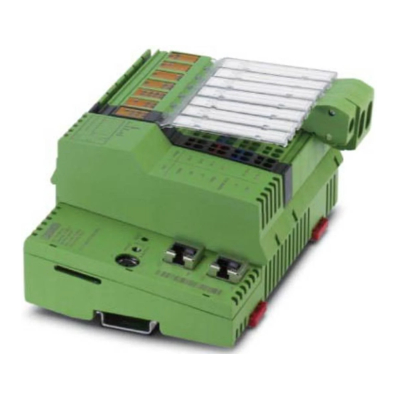
Ethernet system. A single Inline local bus (Figure 2-1) as well as a complete INTERBUS system with a maximum of 4 remote bus levels (Figure 2-2) can be connected to the Inline controller. Inline local bus D-32825 Blomberg ILC 191 ME/AN FAIL Order-No.: 2700074 O1 O2 HW/FW: 00/100 UL FF MAC Addr. -
Page 14: The Inline Controller For Position Control
Inline controller. Analog inputs (ILC 191 ME/AN) are available for the position detection of a tool using a laser measuring system, for example. The ILC 191 ME/INC has digital inputs for incremental en- coders. -
Page 15: The Inline Controller As A Profinet Device In A Profinet Network
Description of the Inline controller 2.2.3 The Inline controller as a PROFINET device in a PROFINET network The following figure shows the example of an ILC 191 ME/AN as a PROFINET device in a PROFINET network. RUN/PROG DISPLAY MRESET RFC 470 PN 3TX L AN1.1... -
Page 16: Applicative System Redundancy Using The Inline Controller
The following figure shows an example of applicative system redundancy. The example shows a PROFINET device with control function (ILC 191 ME/AN) that is connected to a PROFINET network by means of a switch. Identical application programs run on both higher-level PROFINET controllers. -
Page 17: Notes On Using The Inline Controller In Potentially Explosive Areas
Only connect devices to the supply and signal circuits in zone 2 that are suitable for op- eration in potentially explosive areas of zone 2 and for the conditions at the installation location. For reliable operation, the RJ45 connector needs to have a fully functioning locking clip. Repair any damaged connectors immediately. 8607_en_03 PHOENIX CONTACT... -
Page 18: Unpacking The Inline Controller
When handling the Inline controller, observe the necessary safety pre- cautions against electrostatic discharge (ESD) according to EN 61340-5-1 and IEC 61340-5-1. NOTE: To avoid possible damage to the Inline controller, unpack and pack the controller in ac- cordance with the ESD regulations. PHOENIX CONTACT 8607_en_03... -
Page 19: Connection And Operating Elements
R D Y R x D T x D Figure 2-6 Structure of the ILC 191 ME/AN Inline controller The Inline controller consists of the following components: Electronics base Slot for the parameterization memory/card holder (SD card) The SD card is not supplied as standard with the Inline controller. - Page 20 10 Connector 4: connector for PWM outputs 11 Connector 5: connector for RS-485/RS-422 communication 12 Plug 6: plug for counter inputs 13 Connector 7: connector for incremental encoder inputs (asymmetric; channels A, B, and Z) 14 Diagnostic and status indicators 15 End plate PHOENIX CONTACT 8607_en_03...
-
Page 21: Diagnostics And Status Indicators
UM SF FAIL FAIL TxD RxD TxD RxD RS-485 RS-485 Figure 2-8 Diagnostics and status indicators of the ILC 191 ME/AN (A) and the ILC 191 ME/INC (B) Table 2-1 Diagnostic and status indicators Des. Color Status Meaning ETH: state of the Ethernet interface... - Page 22 One or more bus segments in the connected bus switched off Peripheral fault Yellow No peripheral fault on a device in the connected bus Peripheral fault on a device in the connected bus (local bus or remote bus) PHOENIX CONTACT 8607_en_03...
- Page 23 Sending data Communication via RS-485/RS-422 interface Yellow No data being received Flashing Receiving data AI: analog inputs (ILC 191 ME/AN) Sensor supply voltage Green Sensor supply voltage not present/short circuited Sensor supply voltage present AO: analog outputs (ILC 191 ME/AN)
- Page 24 INC: incremental encoder inputs (ILC 191 ME/INC) Level at channel A A1, A2 Yellow 0 signal 1 signal Level at channel B B1, B2 Yellow 0 signal 1 signal Level at channel Z Z1, Z2 Yellow 0 signal 1 signal PHOENIX CONTACT 8607_en_03...
-
Page 25: Mode Selector Switch
Release the switch for less than three seconds. • Set the switch to the MRESET position for three seconds. MRESET FA IL R D Y R xD T xD RUN/PROG Figure 2-9 Mode selector switch of the Inline controller, ILC 191 ME/AN illustrated 8607_en_03 PHOENIX CONTACT... -
Page 26: Reset Button (Concealed)
Only use a parameterization memory provided by Phoenix Contact (for ordering data, see Section “Accessories” on page 154). NOTE: Parameterization memory (SD card) – formatting note The SD card is already formatted and is intended for use with Phoenix Contact devices. Make sure that the SD card is not reformatted. PHOENIX CONTACT... -
Page 27: Inserting/Removing The Parameterization Memory
Figure 2-10 (B) until the snap-on mechanism releases the parameterization memory and partially ejects it from the slot. Remove the parameterization memory. For additional information on the parameterization memory, please refer to Section “Pa- rameterization memory and Internet Explorer” on page 70. 8607_en_03 PHOENIX CONTACT... -
Page 28: Operating The Inline Controller With Or Without Plug-In Parameterization Memory (Sd Card)
The controller therefore does not have an IP ad- dress. When switching on the Inline controller, it automatically sends a Boot_Request, see Sec- tion 3.2 “Assigning the IP address for the controller/BootP server”. PHOENIX CONTACT 8607_en_03... -
Page 29: Internal Basic Circuit Diagram
Q1...4 8 x DI RS-485/ 7,5V RS-422 PWM/ 4 x DO AGND ETH 2TX Figure 2-11 Internal basic circuit diagram of the ILC 191 ME/AN Key: Microprocessor Inverter Protocol chip RS-232 interface Optocoupler Transmitter NPN transistor RJ45 socket Ethernet switch... - Page 30 SD card holder (the SD card is not sup- plied as standard) The gray areas in the basic circuit diagram represent electrically isolated areas: A: Ethernet interface B: Logic C: I/O Other symbols used are explained in the IL SYS INST UM E user manual. PHOENIX CONTACT 8607_en_03...
-
Page 31: Mounting And Removing The Inline Controller
Mount end brackets on both sides of the Inline station. The end brackets ensure that the In- line station is correctly mounted. End brackets secure the Inline station on both sides and keep it from moving from side to side on the DIN rail. Phoenix Contact recommends using CLIPFIX 35-5 end brackets (Order No. 3022276). - Page 32 Then press the top of the connector towards the base until it snaps into the back snap- on mechanism (Figure 2-14, B). Figure 2-13 Snapping on the Inline controller (1) Figure 2-14 Snapping on the Inline controller (2) PHOENIX CONTACT 8607_en_03...
- Page 33 24 V 24 V X2.1 RS485/422 0 - 10 V X2.2 0 - 10 V ILC 191 ME/AN Figure 2-15 Connectors to be removed if terminals are installed next to the Inline con- troller, ILC 191 ME/AN illustrated 8607_en_03 PHOENIX CONTACT...
- Page 34 In particular, make sure that all featherkeys and keyways on adjacent terminals are se- curely interlocked. Observe the following when replacing an Inline controller: Enter the new MAC address when using the BootP server. PHOENIX CONTACT 8607_en_03...
-
Page 35: Communication Paths
The Inline controller cannot be programmed via the RS-232 interface (PRG) or the RS- 485/RS-422 interface. FA IL FA IL FA IL RD Y RD Y RD Y R xD R xD R xD Tx D Tx D Tx D RS-485 Figure 2-18 Communication paths, ILC 191 ME/AN illustrated 8607_en_03 PHOENIX CONTACT... -
Page 36: Ethernet
FA IL R D Y R xD T xD Figure 2-20 Connecting the Ethernet cable to the Inline controller, ILC 191 ME/AN illus- trated The interface is able to switch over the transmitter and receiver automatically (auto cross- over). PHOENIX CONTACT... -
Page 37: Serial Prg Interface (Mini-Din Socket)
The Inline controller cannot be programmed via the RS-232 interface. Assembly instruction FA IL R D Y R x D T x D Figure 2-21 Connecting cable between PC and Inline controller, ILC 191 ME/AN illus- trated 8607_en_03 PHOENIX CONTACT... - Page 38 Communicate with I/O devices (e.g., modem, printer, barcode reader) via function blocks For communication with I/O devices, the PC Worx/PC Worx Express software provides the RS232_INIT, RS232_SEND, and RS232_RECEIVE function blocks, see Section 3.13 on page 81. PHOENIX CONTACT 8607_en_03...
-
Page 39: Interbus
A maximum of 3 branch terminals can be connected to the Inline controller, each of which opens a remote bus (see Figure 2-2 on page 13). 8607_en_03 PHOENIX CONTACT... -
Page 40: Power Supply
Some electronically controlled power supplies have a fall-back characteristic curve (see Figure 2-22). They are not suitable for operation with capacitive loads. A primary-switched power supply (without fall-back characteristic curve) from the QUINT POWER range (see latest catalog from Phoenix Contact) is recommended for Inline controller operation. Overload range... -
Page 41: Connecting The Power Supplies
If the LEDs do not light up or start flashing, there is a serious fault on the Inline controller. In this case, please contact Phoenix Contact. FA IL R D Y UL FF R x D US BF T x D UM SF – – – Figure 2-24 Connecting the supply voltages, ILC 191 ME/AN illustrated 8607_en_03 PHOENIX CONTACT... - Page 42 The Inline controller is grounded when it is snapped onto a grounded DIN rail. Functional earth ground is only used to discharge interfer- ence. NOTE: The maximum total current flowing through the potential jumpers is 8 A. PHOENIX CONTACT 8607_en_03...
-
Page 43: Segment Supply/24 V Main Supply
The rating of the fuse connected upstream must be such that the maximum permissible load current of 2 A is not exceeded. 2.14.7 Jumpers Terminals 1.3 and 2.3 on connector 1 can be jumpered if the communications power and the segment voltage are not to be electrically isolated. 8607_en_03 PHOENIX CONTACT... -
Page 44: Digital Outputs
FA IL R D Y R x D T x D Figure 2-25 Assignment of the terminal points of connector 2, ILC 191 ME/AN illustrated Table 2-3 Assignment of the terminal points of connector 2 Terminal point Assignment Remark Connector 2... - Page 45 Description of the Inline controller Phoenix Contact recommends that connectors for digital 4-channel or 16-channel Inline terminals are used to connect sensors or actuators in 3-wire technology (not supplied as standard, see Section “Accessories” on page 154). The states of the digital outputs are written in PC Worx/PC Worx Express using the corre- sponding system variables, see Section “Status register for local digital inputs and out-...
-
Page 46: Digital Inputs
FA IL R D Y R x D T x D Figure 2-27 Assignment of the terminal points of connector 3, ILC 191 ME/AN illustrated Table 2-4 Assignment of the terminal points of connector 3 Terminal point Assignment Remark Connector 3... -
Page 47: Pulse Direction Outputs And Pwm Function
FA IL R D Y R x D T x D Figure 2-28 Assignment of the terminal points of connector 4, ILC 191 ME/AN illustrated Table 2-5 Assignment of the terminal points of connector 4 Terminal point Assignment Remark Connector 4... -
Page 48: Rs-485/Rs-422 Communication Interface
FA IL R D Y R x D T x D Figure 2-29 Assignment of the terminal points of connector 5, ILC 191 ME/AN illustrated Table 2-6 Assignment of the terminal points of connector 5 Terminal Assignment Full duplex mode... - Page 49 1.1 2.1 1.2 2.2 1.3 2.3 1.4 2.4 Figure 2-30 RS-485/RS-422 interface wiring: full duplex mode FAIL TxD RxD 1.1 2.1 1.2 2.2 1.3 2.3 1.4 2.4 Rx+/ Rx-/ Figure 2-31 RS-485/RS-422 interface wiring: half duplex mode 8607_en_03 PHOENIX CONTACT...
- Page 50 If you use the integrated termination resistor, the polarization of the data cable will also be active. The interface is operated in PC Worx via the RS485_422_INIT, RS485_422_RECEIVE, and RS485_422_SEND function blocks, see Section “Function blocks for RS-485/RS-422 communication” on page 87. PHOENIX CONTACT 8607_en_03...
-
Page 51: Analog Inputs
R D Y R x D T x D Figure 2-33 Assignment of the terminal points of connector 6 on the ILC 191 ME/AN Table 2-7 Assignment of the terminal points of connector 6 on the ILC 191 ME/AN Terminal point Assignment... - Page 52 Differential voltage input with active 3-wire transmitter The states of the local analog inputs can be read using the corresponding system variables in PC Worx, see Section “Status register for local analog inputs and outputs” on page 106. PHOENIX CONTACT 8607_en_03...
-
Page 53: Analog Outputs
R D Y R x D T x D Figure 2-36 Assignment of the terminal points of connector 7 on the ILC 191 ME/AN Table 2-8 Assignment of the terminal points of connector 7 on the ILC 191 ME/AN Terminal point Assignment... -
Page 54: Counter Inputs
Direction input status of channel 1 CI22 Direction input status of channel 2 CI13 Reset input status of channel 1 CI23 Reset input status of channel 2 CI14 Enable input status of channel 1 CI24 Enable input status of channel 2 PHOENIX CONTACT 8607_en_03... - Page 55 2.4) can be used for the evaluation of fast counter pulses. For additional information on the counters, please refer to Section “Function blocks for counter inputs” on page 93. Use shielded cables to ensure interference-free counter operation where possible. Phoenix Contact recommends using the SKS 8-SNS35 shield connection terminal block (Order No. 3062786). 8607_en_03...
-
Page 56: Incremental Encoder Inputs
Input terminal points Channel A, incremental encoder 1 Channel A, incremental encoder 2 Channel B, incremental encoder 1 Channel B, incremental encoder 2 Channel Z, incremental encoder 1 Channel Z, incremental encoder 2 1.4, 2.4 Functional earth ground PHOENIX CONTACT 8607_en_03... - Page 57 Up to two counters for incremental encoders (counter 1: terminal points 1.1 to 1.3; counter 2: terminal points 2.1 to 2.3) can be used for position detection. For additional information on the counters, please refer to Section “Function blocks for incremental encoder inputs” on page 98. 8607_en_03 PHOENIX CONTACT...
- Page 58 ILC 191 ME/X PHOENIX CONTACT 8607_en_03...
-
Page 59: The Inline Controller Under Pc Worx/Pc Worx Express
The PROFINET device function of the controller is not supported by the PC Worx Express software. For information on installing and using PC Worx/PC Worx Express, please refer to the corresponding quick start guide. It can be downloaded at phoenixcontact.net/products and is supplied with the software. 8607_en_03 PHOENIX CONTACT... -
Page 60: Assigning The Ip Address For The Controller/Bootp Server
In an Ethernet network, BootP is used to assign an IP address to a BootP client using a (BootP) BootP server. For this example (ILC 191 ME/AN in the default settings), the ILC 191 ME/AN (BootP client) sends a Boot_Request as a broadcast in the network. The MAC address of the transmitter is sent with the Boot_Request to provide unique identification. - Page 61 Establish an Ethernet connection between your PC and the controller. • In the PC Worx Express menu bar, select the “Extras, BootP/SNMP/TFTP-Configuration...” menu. Figure 3-1 “Extras, BootP/SNMP/TFTP-Configuration...” menu • Activate the “BootP Server active” checkbox. Figure 3-2 “BootP Server active” checkbox 8607_en_03 PHOENIX CONTACT...
- Page 62 ILC 191 ME/X • Switch to the bus configuration workspace. • Select the controller node (in the example: “ILC 191 ME/AN”). • Select the “IP Settings” tab in the “Device Details” window. • Enter the MAC address of the controller (see Figure 3-3 on page 62). It is printed on the device.
-
Page 63: The Inline Controller As A Profinet Device
The PROFINET device function of Inline controllers can also be activated in the PC Worx Express software. This section uses an example to describe how to integrate the ILC 191 ME/AN as a PRO- FINET device. This procedure also applies to the ILC 191 ME/INC. - Page 64 To apply the network settings, you have to reset the controller. • In the “Device Details” window, select the “Ethernet” item under “Extended Settings”. • In the “Activate Network Settings” area, click on the “Reset Control System” button. Figure 3-8 Activate Network Settings: Reset Control System PHOENIX CONTACT 8607_en_03...
- Page 65 Successful execution of the service will be displayed in the status window. Figure 3-10 Activate Network Settings: Service executed successfully Now you can read in the ILC 191 ME/AN as a PROFINET device in a PC Worx project. 8607_en_03 PHOENIX CONTACT...
- Page 66 Subnet mask: 255.255.255.0 – PROFINET device name: ilc-191me-pnd-42-3d-e6 You can read in the ILC 191 ME/AN as a PROFINET device after you have done the follow- ing: – Activated the PROFINET device function of the ILC 191 ME/AN – Installed the PROFINET controller and the PROFINET devices (ILC 191 ME/AN and other PROFINET devices according to your application) –...
- Page 67 Figure 3-12 “Read PROFINET” dialog box • Select the ILC 191 ME/AN and insert it as a PROFINET device by clicking on the “In- sert” button. • Close the dialog box by clicking on the “Close” button.
- Page 68 The process data of the PROFINET device will be displayed on the “Process Data” tab in the “Device Details” window. Figure 3-14 ILC 191 ME/AN as a PROFINET device: Process Data The ILC 191 ME/AN is now available as a PROFINET device in the PC Worx project. PHOENIX CONTACT 8607_en_03...
-
Page 69: Setting The Realtime Clock Under Pc Worx Express
Settings” in the “Device Details” window for the controller in PC Worx Express. To set the realtime clock, proceed as described in the quick start guide for the PC Worx Express version used. Download changes The Inline controller supports the “Download Changes” function. 8607_en_03 PHOENIX CONTACT... -
Page 70: Parameterization Memory And Internet Explorer
FTP functionality” on page 71. • Switch to the bus configuration workspace in PC Worx. • Select the controller, e.g., “ILC 191 ME/AN”, in the “Bus Structure” window. • Select the “Extended Settings” tab in the “Device Details” window. •... -
Page 71: Internet Explorer Ftp Functionality
This setting is restored the next time the Inline controller is rebooted. Value range for the CPU_Set_Value_Request service: Var ID 0172 Value 0000 Deactivate FTP server 0001 Activate FTP server Figure 3-17 Deactivating the FTP server 8607_en_03 PHOENIX CONTACT... -
Page 72: Activating/Deactivating The Http Server
The set HTTP server state is stored retentively and mapped to the ETH_SRV_HTTP_ACTIVE system variable. This setting is restored the next time the Inline controller is rebooted. Value range for the CPU_Set_Value_Request service: Var ID 0173 Value 0000 Deactivate HTTP server 0001 Activate HTTP server PHOENIX CONTACT 8607_en_03... -
Page 73: Activating/Deactivating The Journaling Function
It can be activated or deactivated via the CPU_Set_Value_Request service with Var ID 0194 Value range for the CPU_Set_Value_Request service: Code 02CB Var Count 0001 Var ID 0194 Value 0001 Activate journaling function 0000 Deactivate journaling function Figure 3-18 Activating the journaling function 8607_en_03 PHOENIX CONTACT... -
Page 74: Activating/Deactivating The Mrp Client Function
The Media Redundancy Protocol (MRP) can be used via the Ethernet interfaces of the ILC 191 ME/AN and ILC 191 ME/INC Inline controllers. The controllers support the MRP client function, which can be enabled or disabled via PC Worx as an option. This function is disabled by default. -
Page 75: Function Blocks For Handling Files On The Parameterization Memory
Moves the current file pointer to a new position FILE_NOTIFY Displays files that have recently been created, deleted or modified The function blocks for handling files on the parameterization memory are described in the PC Worx online help. 8607_en_03 PHOENIX CONTACT... -
Page 76: Function Blocks For Ethernet Communication
PCP_READ This block enables data to be read from PCP objects. PCP_SERVER This block enables PCP service indications to be received and responses to be sent. The communication blocks are described in the PC Worx online help. PHOENIX CONTACT 8607_en_03... -
Page 77: Function Blocks For Pulse Width Modulation
If a FALSE signal is present at the REQUEST input, pulse output is stopped. On a new positive edge at the REQUEST input, output of the set pulses starts again. Value range: 0 ... 2 If value 0 is selected for PULSE_CNT, pulses are output continuously. 8607_en_03 PHOENIX CONTACT... -
Page 78: Figure 3-21: Selecting The "Number Of Pulses Reached Px" Event
“Number of pulses reached Px” event must be selected. Figure 3-21 Selecting the “Number of pulses reached Px” event For information on event tasks, please refer to the online help for the PC Worx software. PHOENIX CONTACT 8607_en_03... -
Page 79: Figure 3-22 Signal Curve When The Request Input Is Set To False Too Early (The Done Output Is Only True For One Cycle)
Signal curve when the REQUEST input is set to FALSE too early (the DONE output is only TRUE for one cycle) Key: Signal curve at output P1/P2 (PULSE_CNT parameter = 0) FREQUENCY parameter = 2 FREQUENCY parameter = 4 8607_en_03 PHOENIX CONTACT... -
Page 80: Figure 3-23 Signal Curve When The Output Signal Frequency Is Changed
Output status of the PWM signal (processing carried out) REQUEST DONE Figure 3-25 Signal curve when the output signal frequency is changed and output is continuous (PULSE_CNT = 0) Key: Signal curve at output P1/P2 (PULSE_CNT parameter = 4) PHOENIX CONTACT 8607_en_03... -
Page 81: Function Blocks For Rs-232 Communication
In this case, IP address assignment or work with DIAG+ is only made possible again when: – The RS232_INIT function block is deactivated – Or a new cold restart or warm start is performed for the Inline controller 8607_en_03 PHOENIX CONTACT... - Page 82 Wrong data type applied to PARAMETER input 0x0102 Data type information not available 0x0103 The data type does not correspond to the specification of the T_RS232 data structure 0x0104 The T_RS232 data structure contains an error 0x0105 Multiple instantiation prohibited 0x0160 Unknown protocol PHOENIX CONTACT 8607_en_03...
-
Page 83: Rs232_Send Function Block
Input of the RS232_SEND function block Name Data type Description REQUEST BOOL The function block is executed on a positive edge at this input. The data present at the DATA input is transmitted via the RS-232 interface. 8607_en_03 PHOENIX CONTACT... - Page 84 Multiple instantiation prohibited 0x0107 RS232_INIT not executed successfully 0x0121 No byte array connected to DATA 0x0123 The number of bytes to be sent specified with DATA_COUNT exceeds the internal send buffer 0x0125 The DATA send buffer is full. PHOENIX CONTACT 8607_en_03...
-
Page 85: Rs232_Receive Function Block
BOOL TRUE: There is at least one character left to read in the receive buffer of the RS-232 interface. FALSE: The receive buffer of the RS-232 interface is empty. There are no more characters left to read. 8607_en_03 PHOENIX CONTACT... - Page 86 Status values of the STATUS output (ERROR = TRUE) Value Status 0x0102 Data type information not available 0x0105 Multiple instantiation prohibited 0x0107 RS232_INIT not executed successfully 0x0121 The DATA parameter is not linked 0x0124 Receive buffer does not contain any characters PHOENIX CONTACT 8607_en_03...
-
Page 87: Function Blocks For Rs-485/Rs-422 Communication
Number of stop bits: 1 (default setting), 2 – Hardware flow control: none For the data structure of the T_RS485_422 input parameter, please refer to the online help for the function block in the PC Worx/PC Worx Express software. 8607_en_03 PHOENIX CONTACT... - Page 88 Unknown number of data bits 0x0163 Unknown number of stop bits 0x0164 Unknown flow control 0x020x Incorrect elements in the data type of the T_RS485_422 data structure. x indicates the position of the incorrect element in the PARAMETER pa- rameter. PHOENIX CONTACT 8607_en_03...
-
Page 89: Rs485_422_Send Function Block
Number of characters (still) in the send buffer. DATA_COUNT Number of characters to be written. The number must correspond to the size of the DATA byte array. DATA ARRAY OF Send buffer that contains the characters to be transmitted. BYTE 8607_en_03 PHOENIX CONTACT... -
Page 90: Figure 3-31 Signal Sequence When Request = True
Figure 3-31 Signal sequence when REQUEST = TRUE Key: Data signal when DATA_COUNT parameter = 4 REQUEST = TRUE Positive edge at the DONE output; the four characters to be sent have been sent via the RS-485/RS-422 interface PHOENIX CONTACT 8607_en_03... -
Page 91: Rs485_422_Receive Function Block
BOOL TRUE: There is at least one character left to read in the receive buffer of the RS-485/RS-422 interface. FALSE: The receive buffer of the RS-485/RS-422 interface is empty. There are no more characters left to read. 8607_en_03 PHOENIX CONTACT... -
Page 92: Figure 3-33: Signal Sequence When Receiving A Stream Of Data
The DATA parameter is not linked 0x0124 Receive buffer does not contain any characters Signal sequence diagram REQUEST BUFFER_NOT_EMPTY DONE Figure 3-33 Signal sequence when receiving a stream of data Key: Data signal First two bytes received Last two bytes received PHOENIX CONTACT 8607_en_03... -
Page 93: Function Blocks For Counter Inputs
If the RESET input is set to FALSE, the counting process is continued from the last counter status. FALSE: The counting process is stopped, the counter status is saved. MODE BYTE Operating mode of the counter, see Section 3.15.1 8607_en_03 PHOENIX CONTACT... -
Page 94: Figure 3-35 Selecting The "Event Value Cntx" Event
On a positive edge at this input, the counter status is reset to As long as the input level is set to TRUE, the counter status equals 0. FALSE: The counting process is active, the counter status does not equal 0. PHOENIX CONTACT 8607_en_03... - Page 95 The value at the EDGE input is invalid. 0x10 Invalid instance. An attempt was made to use more than one instance of the function block. If several errors are present, combinations of the status values are output. 8607_en_03 PHOENIX CONTACT...
-
Page 96: Counter Operating Modes
Clock, counting down The counting process (counting direction down) is started when the signal that was previously defined at the EDGE input of the function block is present at the terminal points. The counter counts down. PHOENIX CONTACT 8607_en_03... - Page 97 If a 0 signal is present at the terminal points (MODE 0x02, 0x05, 0x08) or at the input of the function block (MODE 0x00, 0x01, 0x03, 0x04, 0x06, 0x07), the counting process is contin- ued from the last counter status. 8607_en_03 PHOENIX CONTACT...
-
Page 98: Function Blocks For Incremental Encoder Inputs
LOAD_PV input. LOAD_PV BOOL On a positive edge at this input, the current counter status is reset to the preset value that was defined with the PV parameter. PHOENIX CONTACT 8607_en_03... -
Page 99: Figure 3-37 Selecting The "Event Value Inc_Cntx" Event
ERROR BOOL TRUE: An error has occurred. Details are provided by the STATUS output. FALSE: No error. STATUS contains the current value of the internal processing. STATUS WORD Status value of the function block (see Table 3-31) 8607_en_03 PHOENIX CONTACT... -
Page 100: Counter Operating Modes For Incremental Encoders
Counter for incremental encoder and reset function The counting direction at the moment when a positive edge is present at channel A is de- rived from the phase relation of channels A, B, and Z (MODE 0x01 only): PHOENIX CONTACT 8607_en_03... -
Page 101: Figure 3-38: Phase Relation Of Channels For Counting Direction Up
Channel A Channel B Channel Z 8607A002 Figure 3-38 Phase relation of channels for counting direction up Channel A Channel B Channel Z 2 -1 2 -2 8607A003 Figure 3-39 Phase relation of channels for counting direction down 8607_en_03 PHOENIX CONTACT... -
Page 102: Alignment
When inserting padding bytes, observe the memory alignment method of the control- lers used in the application (1-byte, 2-byte or 4-byte alignment). Program example with The following program example shows how data gaps are filled. data gaps Figure 3-40 Example programming PHOENIX CONTACT 8607_en_03... -
Page 103: Figure 3-41: Alignment - Padding Bytes In Data Gaps
Struct3 does not receive any padding bytes as the maximum alignment corresponds to one byte. Due to the padding byte that belongs to the Struct2 structure, the Struct3 structure starts at an even address in Struct4. Array1 receives two padding bytes corresponding to two consecutive Struct2 structures. 8607_en_03 PHOENIX CONTACT... -
Page 104: Figure 3-42 Example Programming With Padding Bytes
The following program shows an example of how to fill data gaps in your application pro- data gaps gram. Fill data gaps, which are to be expected due to the memory alignment, with applica- tion data (padding bytes in Figure 3-42). Figure 3-42 Example programming with padding bytes PHOENIX CONTACT 8607_en_03... -
Page 105: System Variables And Status Information
State of local output OUT1 ONBOARD_OUTPUT_BIT1 BOOL State of local output OUT2 ONBOARD_OUTPUT_BIT2 BOOL State of local output OUT3 ONBOARD_OUTPUT_BIT3 BOOL State of local output OUT4 ONBOARD_OUTPUT_OVERLOAD_0_3 BOOL Overload at at least one of the local outputs 8607_en_03 PHOENIX CONTACT... -
Page 106: Status Register For Local Analog Inputs And Outputs
If the controller is in the STOP state, the set substitute value is output. Exception: the controller is in the STOP state when switched on. In this case the value 0 is output. The analog output is overloaded. The desired voltage cannot be output. PHOENIX CONTACT 8607_en_03... -
Page 107: Representation Of Measured Values For The Local Analog Inputs
4.3.1 Representation of measured values for the local analog in- puts This section applies for the ILC 191 ME/AN. The measured values are depicted in IB IL format. The measured value is represented in bits 14 to 4. An additional bit (bit 15) is available as an error bit. -
Page 108: Representation Of Output Values For The Local Analog Outputs
4.3.2 Representation of output values for the local analog out- puts This section applies for the ILC 191 ME/AN. The output values are depicted in IB IL format. The output value is represented in bits 14 to 0. An additional bit (bit 15) is available as a sign bit. -
Page 109: Status Register For Counter Inputs
Meaning INC_CNT1_A BOOL Counter 1, channel A INC_CNT1_B BOOL Counter 1, channel B INC_CNT1_Z BOOL Counter 1, channel Z INC_CNT2_A BOOL Counter 2, channel A INC_CNT2_B BOOL Counter 2, channel B INC_CNT2_Z BOOL Counter 2, channel Z 8607_en_03 PHOENIX CONTACT... -
Page 110: Diagnostic Status Register
Faulty data cycles MASTER_DIAG_STATUS_REG_WARN BOOL Defined warning time exceeded MASTER_DIAG_STATUS_REG_QUAL BOOL Defined error density exceeded MASTER_DIAG_STATUS_REG_SSINFO BOOL A message is present MASTER_DIAG_STATUS_REG_HI BYTE Master diagnostic status register, high byte MASTER_DIAG_STATUS_REG_LOW BYTE Master diagnostic status register, low byte PHOENIX CONTACT 8607_en_03... -
Page 111: Diagnostic Parameter Register
System variables of the diagnostic parameter register System variable Type Meaning MASTER_DIAG_PARAM_REG_HI BYTE Diagnostic parameter register, high byte MASTER_DIAG_PARAM_REG_LOW BYTE Diagnostic parameter register, low byte MASTER_DIAG_PARAM_2_REG_HI BYTE Extended diagnostic parameter register, high byte MASTER_DIAG_PARAM_2_REG_LOW BYTE Extended diagnostic parameter register, low byte 8607_en_03 PHOENIX CONTACT... -
Page 112: Profinet Register
PROFINET controller. PND_IO_DRIVEN_BY_PLC Applicative system redundancy: Specifies from which higher-level PROFINET controller the data in the PROFINET device originates (see Figure 2-5 on page 16). No PROFINET controller Controller A Controller B PHOENIX CONTACT 8607_en_03... -
Page 113: Iec 61131 Runtime System
If this maximum number is reached, the controller is stopped. PLC_ERRORS DINT Number of “errors, warnings, and logging events” currently entered. PLC_TASK_DEFINED Number of tasks used PLC_TASK_1 Record, Information regarding task 1 elements = 17 PLC_TASK_8 Record, Information regarding task 8 elements = 9 8607_en_03 PHOENIX CONTACT... -
Page 114: Control Processor
The 24 V main power supply is OK. POWER_SUPPLY_INPUTS_OK BOOL The 24 V power supply for the local inputs is OK. POWER_SUPPLY_OUTPUTS_0_3_OK BOOL The 24 V power supply for the local outputs is OK. (Bits 0 to 3) PHOENIX CONTACT 8607_en_03... -
Page 115: Mode Selector Switch
System time Table 4-16 System variables of the system time System variable Type Meaning RTC_HOURS System time (hours) RTC_MINUTES System time (minutes) RTC_SECONDS System time (seconds) RTC_DAY System time (day) RTC_MONTH System time (month) RTC_YEAR System time (year) 8607_en_03 PHOENIX CONTACT... - Page 116 ILC 191 ME/X PHOENIX CONTACT 8607_en_03...
-
Page 117: Easy Motion Function Block Library
Hardware structure of an Easy Motion application with the ILC 191 ME/AN and ILC 191 ME/INC Inline controllers The ILC 191 ME/AN and ILC 191 ME/INC Inline controllers can be used to control step motor drivers. In PC Worx, the connected step motor drivers are controlled via the pulse di- rection outputs of the Inline controller using the blocks of the Easy Motion function block li- brary (ILCME_MCE). -
Page 118: Figure 5-2 Direction Output: Direction Of Rotation Right
8607A005 Figure 5-2 Direction output: direction of rotation right 8607A006 Figure 5-3 Direction output: direction of rotation left 8607A007 Figure 5-4 Pulse output: ratio of frequency to speed PHOENIX CONTACT 8607_en_03... -
Page 119: Characteristics Of One-Dimensional Positioning Axes
The software limit switches are not physical switching ele- ments but are specified in the PC Worx software depend- ing on the application. Home position switch: Specifies a reference point for the limits of the positioning and working ranges. 8607_en_03 PHOENIX CONTACT... -
Page 120: Figure 5-5 Diagram Of An Axis Application
If the axis coordinate of the positioning object does not match the actual position in the application, the desired setpoint positions cannot be approached. This may damage the positioning object and system parts. • Perform homing prior to the initial move. PHOENIX CONTACT 8607_en_03... -
Page 121: Homing (Dynamic Homing)
The reference point is set when the falling edge of the home position switch signal is detected. 6977B017 Figure 5-6 Homing: procedure 1 8607_en_03 PHOENIX CONTACT... -
Page 122: Figure 5-7: Homing: Procedure 2
Homing is started in the positive direction and is also carried out in the positive direction. The homing sequence is the same as for procedure 1, however, travel is started in the pos- itive direction. 6977B019 Figure 5-8 Homing: procedure 3 PHOENIX CONTACT 8607_en_03... -
Page 123: Figure 5-9: Homing: Procedure 4
Homing is started in the positive direction and is carried out in the negative direction. The homing sequence is the same as for procedure 2, however, travel is started in the positive direction. 6977B020 Figure 5-9 Homing: procedure 4 8607_en_03 PHOENIX CONTACT... -
Page 124: Starting Up The Easy Motion Function Block Library
Activate the Execute inputs of blocks M191_Power, M191_HomePARA and M191_Home one after the other in order to activate the function blocks one after the other and to start homing. Please note: When activating the function blocks, it is essential to follow the sequence specified here. PHOENIX CONTACT 8607_en_03... -
Page 125: Function Blocks Of The Easy Motion Function Block Library
This function block should also be used if a move was started but could not be carried out due to an error on the driver block. In this case, the move should be stopped using the M191_Stop block. 8607_en_03 PHOENIX CONTACT... -
Page 126: M191_Drv1 And M191_Drv2 Function Blocks
REAL Maximum permissible deceleration in mm/s xEnableABS1 BOOL Input for connecting the M191_MoveAbsolute function block (function block for performing an absolute move) TRUE: An absolute move is started or already active FALSE: No absolute move is started PHOENIX CONTACT 8607_en_03... - Page 127 Input for connecting a digital input of the Inline controller which is con- nected to the home position switch of the axis TRUE: Home position switch has been reached FALSE: Home position switch has not yet been reached 8607_en_03 PHOENIX CONTACT...
-
Page 128: Table 5-3 Outputs Of The M191_Drv Function Block
M191_DRV driver block. C300 The two hardware limit switches (positive and negative) have been mixed up on the driver block or one of the two hardware limit switches has been reached. PHOENIX CONTACT 8607_en_03... -
Page 129: M191_Power Function Block
The move in a positive direction is enabled. FALSE: The move in a positive direction is not enabled. EnableNegative BOOL TRUE: The move in a negative direction is enabled. FALSE: The move in a negative direction is not enabled. 8607_en_03 PHOENIX CONTACT... -
Page 130: Table 5-7 Outputs Of The M191_Power Function Block
Data structure for data exchange between the function blocks of the Easy Motion library Table 5-9 Error values of the ErrorID output (Error = TRUE) Name Description 0000 No error occurred. 0001 The axis is in the “StandStill” state. PHOENIX CONTACT 8607_en_03... -
Page 131: M191_Homepara Function Block
REAL Home position in mm Absolute position after homing to the desired side of the home position switch (default value: 0 mm (input not connected)) iModeREF Homing procedure, permissible value range: 1 ... 4, see Section 5.2 8607_en_03 PHOENIX CONTACT... -
Page 132: Table 5-11 Outputs Of The M191_Homepara Function Block
Invalid value for rAcceleration (rAcceleration ≤ 0 or rAcceleration > rLimitACC or rLimitACC ≤ 0) 00A1 No homing procedure specified (permissible value range: 1 ... 4) C100 Missing values at at least one of the lrMotorTurnMM, iMotorTurnSteps, lrSoftEndDCC inputs PHOENIX CONTACT 8607_en_03... -
Page 133: M191_Home Function Block
An error has occurred. Details are provided by the ErrorID out- put. FALSE: No error. ErrorID contains the current value of the internal pro- cessing. ErrorID WORD Error value of the error that occurred (see Table 5-17) 8607_en_03 PHOENIX CONTACT... -
Page 134: Table 5-16 Input/Output Of The M191_Home Function Block
Error values of the ErrorID output (Error = TRUE) Name Description 0000 No error occurred. 0001 The axis is not in the “StandStill” state. 0006 Enabling by M191_Power function block is missing. 0061 At least one missing error at the rVelocity, rVelocityREF and rAcceleration inputs PHOENIX CONTACT 8607_en_03... -
Page 135: M191_Moveabsolute Function Block
BOOL TRUE: The function block is executed. FALSE: The function block is not executed or has already been execut- ed successfully. Active BOOL The Active output must be connected to the xEnableABS input of the driver block. 8607_en_03 PHOENIX CONTACT... -
Page 136: Table 5-20 Input/Output Of The M191_Moveabsolute Function Block
Missing values at at least one of the lrMotorTurnMM, iMotorTurnSteps, lrSoftEndDCC inputs C300 The two hardware limit switches (positive and negative) have been mixed up on the driver block or one of the two hardware limit switches has been reached. PHOENIX CONTACT 8607_en_03... -
Page 137: M191_Moverelative Function Block
BOOL TRUE: The function block is executed. FALSE: The function block is not executed or has already been execut- ed successfully. Active BOOL The Active output must be connected to the xEnableREL input of the driver block. 8607_en_03 PHOENIX CONTACT... -
Page 138: Table 5-24 Input/Output Of The M191_Moverelative Function Block
Missing values at at least one of the lrMotorTurnMM, iMotorTurnSteps, lrSoftEndDCC inputs C300 The two hardware limit switches (positive and negative) have been mixed up on the driver block or one of the two hardware limit switches has been reached. PHOENIX CONTACT 8607_en_03... -
Page 139: M191_Movevelocity Function Block
Acceleration in mm/s Permissible value range: 0 < Acceleration ≤ rLimitACC of the driver block Deceleration REAL Deceleration in mm/s Permissible value range: 0 < Deceleration ≤ rLimitDCC of the driver block Direction Moving direction Positive direction Negative direction 8607_en_03 PHOENIX CONTACT... -
Page 140: Table 5-27 Outputs Of The M191_Movevelocity Function Block
Missing values at at least one of the lrMotorTurnMM, iMotorTurn- Steps, lrSoftEndDCC inputs C300 The two hardware limit switches (positive and negative) have been mixed up on the driver block or one of the two hardware limit switches has been reached. PHOENIX CONTACT 8607_en_03... -
Page 141: M191_Reset Function Block
Data structure for data exchange between the function blocks of the Easy Motion library Table 5-33 Error values of the ErrorID output (Error = TRUE) Name Description 0000 No error occurred. 0001 The drive is in the “ErrorStop” state. 8607_en_03 PHOENIX CONTACT... -
Page 142: M191_Stop Function Block
An error has occurred. Details are provided by the ErrorID out- put. FALSE: No error. ErrorID contains the current value of the internal pro- cessing. ErrorID WORD Error value of the error that occurred (see Table 5-37) PHOENIX CONTACT 8607_en_03... -
Page 143: Table 5-36 Input/Output Of The M191_Stop Function Block
Description 0000 No error occurred. 0001 The axis is in the “ErrorStop” state. 0006 Enabling by M191_Power function block is missing. 0009 Invalid value for Deceleration (Deceleration ≤ 0 or Deceleration > rLimitDCC or rLimitDCC ≤ 0) 8607_en_03 PHOENIX CONTACT... -
Page 144: Simple Application Example
M191_HomePARA function block must be activated. Then, the M191_Home function block must be activated in order to start homing. After homing, absolute moves can be performed using the M191_MoveAbsolute function block. Figure 5-19 Application example for performing an absolute move PHOENIX CONTACT 8607_en_03... -
Page 145: Technical Data And Ordering Data
1.5 mm General supply Use a power supply without fall-back characteristic curve (see Section “Sizing of the power supply” on page 40). 24 V main supply U ILC 191 ME/AN ILC 191 ME/INC Connection technology Spring-cage terminal blocks Nominal value... - Page 146 Provide external protection for the 24 V area. The power supply unit must be able to supply 4 times (400%) the nominal current of the external fuse, to ensure that the fuse blows safely in the event of an error. 24 V supply U ILC 191 ME/AN ILC 191 ME/INC Connection technology...
- Page 147 0.5 A DC Protective measures Electric short-circuit protection PROFINET Type PROFINET device Specification Performance class Update rate ≥ 1 ms Number of slots Vendor ID ILC 191 ME/AN 00B0 /176 ILC 191 ME/INC 00B0 /176 Device ID 0096 /150 0097 /151 INTERBUS...
- Page 148 7 mA, typical; 15 mA, maximum Hardware filter times (typical), inputs I1 to I8 Signal change 0 3 ms Signal change 1 3 ms Permissible cable length to the sensor 30 m (to ensure conformance with EMC Directive 2004/108/EC) PHOENIX CONTACT 8607_en_03...
- Page 149 150 kHz RS-485/RS-422 interface Transmission speed 115 kbaud, maximum Operating modes Full duplex, half duplex Electrical isolation Analog inputs (ILC 191 ME/AN only) Number A/D resolution 11 bits Measured value representation 0 V ... 10 V Data formats IB IL...
- Page 150 I1 to I8, E, Q1 to Q4 Supply voltages US, UM, UL PROFINET BF, SF Analog inputs and outputs (ILC 191 ME/AN) UA, O1 to O2 Counter inputs (ILC 191 ME/INC) C11 to C24 Incremental encoder inputs (ILC 191 ME/INC)
- Page 151 4 days Resistance of housing material to termites Resistant Resistance of housing material to fungal decay Resistant Mechanical tests Vibration resistance according to EN 60068-2-6, IEC 60068-2-6 Operation: 5g Shock test according to EN 60068-2-27, IEC 60068-2-27 8607_en_03 PHOENIX CONTACT...
-
Page 152: Tolerance Values For The Analog Inputs
IEC 61000-4-4 Additional tolerances may occur due to the influence of high-frequency electromagnetic in- terference caused by wireless transmission systems in the immediate vicinity. The specified values refer to nominal operation. The components are directly exposed to interference PHOENIX CONTACT 8607_en_03... -
Page 153: Tolerance Values For The Analog Outputs
The tolerances specified above can be reduced through additional shielding measures for the I/O module (e.g., use of a shielded control box/control cabinet, etc.). 8607_en_03 PHOENIX CONTACT... -
Page 154: Ordering Data
6.2.4 Documentation Description Type Order No. Pcs. / Pkt. “Modbus TCP with Phoenix Contact controllers” application note AH EN MODBUS TCP – “Configuring and installing the INTERBUS Inline product range” user manual IB IL SYS PRO UM E – “Automation terminals of the Inline product range” user manual IL SYS INST UM E –... -
Page 155: A Appendix: Service And Maintenance
No firmware update is required for normal system operation. To update the firmware, please proceed as described in the “Firmware update ILC 1.../3..., RFC 4...” application note. It can be downloaded at phoenixcontact.net/products. 8607_en_03 PHOENIX CONTACT... -
Page 156: A 3 Connecting Unshielded Cables
Push a screwdriver into the actuation shaft of the appropriate terminal point (Figure A-1, A) so that you can insert the wire into the spring opening. Phoenix Contact recommends the SFZ 1-0,6x3,5 screwdriver (Order No. 1204517). • Insert the wire (Figure A-1, B). Remove the screwdriver from the opening. This clamps the wire. -
Page 157: Connecting The Shield
Insert the shield connection clamp according to the conductor cross section. Insert the cable (C in Figure A-2). • Close the shield connection (D in Figure A-2). • Fasten the screws of the shield connection tightly using a screwdriver (E in Figure A-2). 8607_en_03 PHOENIX CONTACT... - Page 158 ILC 191 ME/X PHOENIX CONTACT 8607_en_03...
-
Page 159: B Appendix For Document Lists
Remote bus levels ................13 Figure 2-3: The Inline controller for position control ..........14 Figure 2-4: PROFINET device using the ILC 191 ME/AN as an example ..... 15 Figure 2-5: Applicative system redundancy – example ......... 16 Figure 2-6: Structure of the ILC 191 ME/AN Inline controller ......... - Page 160 “Read PROFINET” dialog box ............. 67 Figure 3-13: ILC 191 ME/AN inserted as a PROFINET device ........ 68 Figure 3-14: ILC 191 ME/AN as a PROFINET device: Process Data ...... 68 Figure 3-15: Extended Settings: Open FTP Folder on Device ........ 70 Figure 3-16: Internet Options: Enable folder view for FTP sites ......
- Page 161 Error location in the diagnostic parameter register ......111 Section 5 Figure 5-1: Hardware structure of an Easy Motion application with the ILC 191 ME/AN and ILC 191 ME/INC Inline controllers ....117 Figure 5-2: Direction output: direction of rotation right ........118 Figure 5-3: Direction output: direction of rotation left ...........
- Page 162 M191_Reset function block .............. 141 Figure 5-18: M191_Stop function block ..............142 Figure 5-19: Application example for performing an absolute move ..... 144 Appendix A Figure A-1: Connecting unshielded cables ............156 Figure A-2: Connecting the shield ............... 157 PHOENIX CONTACT 8607_en_03...
-
Page 163: B 2 List Of Tables
Assignment of the terminal points of connector 5 ........ 48 Table 2-7: Assignment of the terminal points of connector 6 on the ILC 191 ME/AN..................51 Table 2-8: Assignment of the terminal points of connector 7 on the ILC 191 ME/AN..................53... - Page 164 System variables of the power storage and realtime clock ....114 Table 4-14: System variables of the power supplies..........114 Table 4-15: System variables of the mode selector switch ........115 Table 4-16: System variables of the system time..........115 PHOENIX CONTACT 8607_en_03...
- Page 165 Error values of the ErrorID output (Error = TRUE)......141 Table 5-34: Inputs of the M191_Stop function block..........142 Table 5-35: Outputs of the M191_Stop function block .......... 142 Table 5-36: Input/output of the M191_Stop function block........143 8607_en_03 PHOENIX CONTACT...
- Page 166 ILC 191 ME/X Table 5-37: Error values of the ErrorID output (Error = TRUE)......143 Appendix A Table A-1: Installation error causes and remedies ..........155 PHOENIX CONTACT 8607_en_03...
-
Page 167: B 3 Index
For counter inputs ..........93 For Ethernet communication ......... 76 Basic circuit diagram For handling files on the parameterization memory 75 ILC 191 ME/AN ............. 29 For incremental encoder inputs ......98 ILC 191 ME/INC ............ 30 For PCP communication........76 Basic wiring of an output .......... - Page 168 PROFINET device ..........63 Reading in PROFINET .......... 66 PWM outputs .............. 47 Realtime clock............. 69 Removal..............31, 33 Replacement............... 34 Reset button..............26 Resetting the Inline controller ........ 26 Resetting the controller ..........64 RS-232 cable .............. 37 PHOENIX CONTACT 8607_en_03...
Need help?
Do you have a question about the ILC 191 ME/AN and is the answer not in the manual?
Questions and answers