
Related Manuals for AGFA Jeti Tauro H3300LED Series


Summary of Contents for AGFA Jeti Tauro H3300LED Series
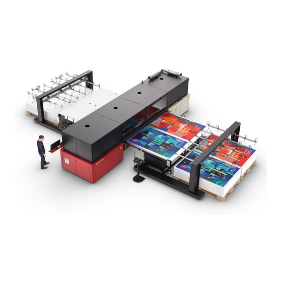
- Page 1 Fig. Tauro H3300led full automation Operator Manual Jeti Tauro H3300 LED HYBRID UV INKJET PRINTER Revision 1.0...
- Page 2 EC Declaration of Conformity Agfa Graphics Revision 1.0...
- Page 3 For more information on Agfa Graphics products, please visit www.agfagraphics.com. Agfa and Agfa Jeti are trademarks of Agfa-Gevaert N.V., Belgium or its affiliates. Tauro is a trademark of Agfa Graphics N.V., Belgium or one of its affiliates. All other trademarks are held by their respective owners and are used in an editorial fashion with no intention of infringement.
- Page 4 It prints to widths as great as 3.34 meters and can accommodate rigid media up to 4.0 meters in length. Driven by Asanti workflow technology and optimized to work with Agfa’s high-pigmented UV-inks, every aspect of the Jeti Tauro is perfectly suited to the quality and productivity demands of high-end sign and display printers.
- Page 5 Document Conventions The following symbols and text conventions are used throughout this document. Icon Indicates Note: A note contains additional information which may be useful to you but which is not vitally important to work safely. Information about actions that could cause damage to the system or equipment.
-
Page 6: Table Of Contents
Table of Content Health & Safety • Safety Labels on the Jeti Tauro H3300LED ..................... 01 • Fire prevention ..............................02 • Ventilation ................................02 • Waste Management ............................02 • Rules for Safe Operation ............................ 03 • Overview of the Safety Mechanisms ....................... 03 Tauro H3300LED ..............................04 Tauro H3300LED RTR ............................05 Tauro H3300LED Full Automation ........................06... - Page 7 Table of Content Operator Maintenance Cabinet ........................21 LED Protection Unit (option) ..........................23 IV. Startup and Shutdown • Chapter Overview ..............................25 • Introduction ................................25 • Startup the Printer .............................. 26 Procedure 1: How to Perform the Daily Start-up ....................26 Purge and Clean ............................
- Page 8 Table of Content Checking Print Quality ............................67 Printing a Test Pattern for Expert Analysis ......................67 VI. GUI Presentation • Overview ................................68 • Graphical User Interface Main Windows ......................69 Main GUI Window - Status Mode ......................69 Engine Status ................................69 Machine Status Overview ............................71 System status overview ............................72 Ink status overview ..............................72...
-
Page 9: Health & Safety
Chapter 1 Health & Safety This section contains information related to the safe operation of the Jeti Tauro H3300LED and to the safe- ty of the user and the persons around the equipment. Anybody who uses the printer must read this chapter carefully before starting the machine. -
Page 10: Fire Prevention
If solvent soaked rags or absorbents must also be disposed of in a closed fireproof container and labeled as hazardous waste. Locate both waste tanks at least 7.6 m (25 Ft.) from the Jeti Tauro H3300LED. Do not discharge waste tanks in sewers. Waste tanks are banned from landfill sight. Agfa Graphics Revision 1.0 Chapter 1... -
Page 11: Rules For Safe Operation
Operators can operate the printer and perform the maintenance tasks listed in this manual. All other maintenance and service actions are reserved (password protected) for Service and/or Agfa service. Failure to comply with these measures of safe operation and maintenance may result in personal injury or machine damage. -
Page 12: Tauro H3300Led
REAR or INPUT LEFT or HOME FRONT or OUTPUT RIGHT or AWAY Fig.1-1: Emergency button (front view) REAR or INPUT LEFT or HOME RIGHT or AWAY Fig.1-2: Emergency button (top view) Tauro H3300LED RTR Agfa Graphics Revision 1.0 Chapter 1... - Page 13 REAR or INPUT LEFT or HOME FRONT or OUTPUT RIGHT or AWAY Fig.1-3: Emergency button R2R (front view REAR or INPUT LEFT or HOME RIGHT or AWAY FRONT or OUTPUT Fig.1-4: Emergency button R2R (top view) Agfa Graphics Revision 1.0 Chapter 1...
-
Page 14: Tauro H3300Led Full Automation
- Outside all arms of the loader and unloader • For detailed instructions about Full Automation see User Manual Full automation Fig.1-6: Emergency button unloader & loader Fig.1-7: Emergency buttons full automation (top view) Agfa Graphics Revision 1.0 Chapter 1... -
Page 15: Emergency Stop Button Operation
• When the system and the operator are safe, rotate the emergency stop button to reset it. • On the printer console GUI, press the “Re-init” button in the alarm window • The system should recover after a few minutes. Agfa Graphics Revision 1.0 Chapter 1... -
Page 16: Access Panels
On the away side of the Jeti Tauro H3300LED, three white doors give access to the service cabinet for weekly maintenance and service. Each white door features a locking mechanism. Only qualified key operators or service engineers are entitled to unlock the white doors. Agfa Graphics Revision 1.0 Chapter 1... - Page 17 Each operator cabinet red door and each service cabinet white door features a lock open mechanism to keep the door open. Lift the lock mechanism bar with your foot to close the door. Fig.1-10: Door lock Mechanism Agfa Graphics Revision 1.0 Chapter 1...
-
Page 18: Operator Doors Interlocks
When the doors are open the safety circuit is triggered and motion will be disabled Fig.1-11: Location f the Operator Door Inter Fig.1-.12: Door Interlock Key and Switch Agfa Graphics Revision 1.0 Chapter 1... -
Page 19: Light Indicator
Green Static Preparing Green Static Printing Green Blinking Stand by Orange Static Error Blinking Whether the Jeti Tauro H3300LED is initializing, printing or in error, a blinking state always calls for the user’s attention. Agfa Graphics Revision 1.0 Chapter 1... -
Page 20: Various
• Do not use ingestion as a means of identifying a chemical. Ink and Solvent First Aid Measures • Agfa Graphics recommends the installation of a safety eyewash station close to the chemical use area. Agfa Graphics Revision 1.0... - Page 21 • Agfa Graphics recommends storing all chemicals, lubricants and solvent in a chemical safety cabinet at least 3 meters (10 feet) away from the machine. • Agfa Graphics promotes the use of local laws and regulations to handle store and dispose of chemicals, lubricants and solvents.
-
Page 22: System Specifications
Chapter 2 System specifications Introduction: System specifications This chapter contains information on the Jeti Tauro H3300 LED printer system specifications. • Printing Resolutions • Application Scope and Printing Dimensions • Chemistry • Noise Emissions • Electrical and Network Requirements • Air Ventilation and Environmental Requirements Printing Resolutions The Jeti Tauro H3300 LED can print using the following resolutions. - Page 23 The Jeti Tauro H3300 LED uses UV LED ink technology. Noise Emissions This system’s airborne noise emissions do not exceed 72 dB. Follow local health and safety require- ments. Air Ventilation and Environmental Requirements Refer to pre-site and installation documentation. Agfa Graphics Revision 1.0 Chapter 2...
-
Page 24: Overview
Chapter 3 Overview Introduction: Overview This chapter contains overview information on the Jeti Tauro H3300 LED printer. • Slow Scan and Fast Scan Definition • Shuttle Components • Ink System • Operator Maintenance Cabinet • LED Protection Unit Slow Scan and Fast Scan Definition During production, the shuttle travels along the beam by means of a lin-... -
Page 25: Pedals
Preparing Turns vacuum on/off Slot 2: Up/down Print start movement in manual sheet mode Printing Disabled Disabled Disabled Agfa Graphics Revision 1.0 Chapter 3... -
Page 26: Shuttle Components
(outlined in green in Fig.3-4) • Two LED Protection Units (outlined in green in Fig.3-5) • Two collision sensors (CS) (outlined in blue in Fig.3-5) • One anti-static ionizer (AS) (outlined in red in Fig.3-5) Fig.3-4: Carriage Front Agfa Graphics Revision 1.0 Chapter 3... -
Page 27: Ink System
The ink system comprises all the components of the Jeti Tauro H3300 LED in contact with the inks. It starts with the Ink Supply Systems (ISS) where the operator fills the system with ink and ends in the color bars with the print head firing the ink on the media. Agfa Graphics Revision 1.0 Chapter 3... -
Page 28: Color Ink Refill Cabinet
ISS only or a white ISS and a primer ISS. Each ISS includes an 8-liter tank, a LED, a level sensor, a pump, a filter and an inlet blade. Fig.3-7: Specialty Ink Refill Cabinet Agfa Graphics Revision 1.0 Chapter 3... -
Page 29: Operator Maintenance Cabinet
The doors can be opened when the Re-Init button is enabled in the Purge Color- (outlined in red in Fig.3-9) bars pop-up screen. Access through the colorbars overview screen. Fig.3-9: Purge Colorbars Pop-Up Screen Agfa Graphics Revision 1.0 Chapter 3... - Page 30 Media Input side of the engine due to equipment vibra- tion. This would trigger an interlock alarm and interrupt the production. The system must be initialized each time the drip tray leaves its home position. Agfa Graphics Revision 1.0 Chapter 3...
-
Page 31: Led Protection Unit (Option)
In non Printing status Fig.3-12: LED Protection Unit Status The system is equipped with a LED protection unit, to capture any free airborne ink drops into a filter (see Fig.3-13) Filter Handle Fig.3-13: LED Protection Unit Filter Agfa Graphics Revision 1.0 Chapter 3... - Page 32 Jeti Tauro H3300LED Operator Manual Agfa Graphics Revision 1.0 Chapter 3...
-
Page 33: Startup And Shutdown
Chapter 4 Startup and Shutdown Introduction This chapter contains information and procedure for starting up and shutting down the Jeti Tauro H3300 LED printer. • Startup the Printer Purge and Clean • • Perform Nozzle Check Selecting Own Jobs from Asanti •... - Page 34 Note: Make sure that both networks are available before proceeding. Fig.4-3: Network Window - Step 6: Launch the Tauro GUI (Graphic User Interface) from its desktop icon and wait for the application to completely launch. Fig.4-5: Jeti Tauro H3300 LED GUI Icon Agfa Graphics Revision 1.0 Chapter 4...
- Page 35 - Step 8: Purge and wipe all heads Important: Purging is allowed while the system is warming up (icon outlined in green in Fig.4-7) but printing is not allowed until all heads and head plates are heated. Fig.4-7: Shuttle Status Screen Agfa Graphics Revision 1.0 Chapter 4...
- Page 36 - Step 10: Print and check the nozzle test pattern for colors, white and primer (see Procedure: “How to Perform Nozzle check manual mode”). Technical images are located under the filter icon. - Step 11: Choose a job and start printing Agfa Graphics Revision 1.0 Chapter 4...
-
Page 37: Purge And Clean
- Step 2: “Purge Colorbars” pop up window select “Purge” use always long purge time. Sub tank is purging Sub tank is ready Fig.4-9: Purge Colorbars Pop up At the start of the purge cycle the automatic drip tray is lowered. Agfa Graphics Revision 1.0 Chapter 4... - Page 38 Fig.4-11: Front Operator Cabinet Access Doors Note: This provides access to the print heads base plates. Fig.4-12: Print Heads Base Plates - Step 5: Clean the heads sequentially using a dry lint free cleaning cloth. Cleaning is performed in Agfa Graphics Revision 1.0 Chapter 4...
- Page 39 - Step 6: Close the red doors . - Step 7: Re-initialize the Jeti Tauro H3300 LED from the Purge Colorbars pop-up. Fig.4-14: Re-initialize Button - Step 8: Proceed to Procedure: “How to Select Operational Mode in the System Tab”. Agfa Graphics Revision 1.0 Chapter 4...
-
Page 40: Procedure 4-3: How To Select Operational Mode In The System Tab
If the mode is changed afterwards, the slot configuration is changed to the default for that selected mode. - Step 4: Check if the corresponding Rolls/setbar “Slot Configuration” is installed (see Fig.4-16) Fig.4-16: Slot Configuration - Step 5: Proceed to “Perform Nozzle Check”. Agfa Graphics Revision 1.0 Chapter 4... -
Page 41: Perform Nozzle Check
- Step 7: Add the selected layout to the queue (outlined in magenta in Fig. 4.17). - Step 8: Open the queue pane outlined in in Fig. 4.17) and start the queue. (outlined in blue Fig.4-18) Fig.4-18: Queue Pane Agfa Graphics Revision 1.0 Chapter 4... - Page 42 - Step 11: Press the left foot pedal (see Fig.4-21). This turns the media belt vacuum ON. Fig.4-21: Foot Pedal left - Step 12 Press the right foot pedal. This initiates the printing process - Step 13 Proceed to Procedure: “How to Check the Color Nozzles”. Agfa Graphics Revision 1.0 Chapter 4...
-
Page 43: Procedure 5: How To Check The Color Nozzles
Procedure: How to Check the White Nozzles - Step 1: Print the “NozzleCheckWhite” built in patterns to confirm the white nozzles functionality. Fig.4-24: Check White Nozzles - Step 2: Proceed to “Selecting Own Jobs from Asanti” Agfa Graphics Revision 1.0 Chapter 4... -
Page 44: Selecting Own Jobs From Asanti
• C: Change General settings directly in the GUI. Head gap, Uv power, ... • D: Change Density settings directly in the GUI. • E: Change Requested number of copies directly in the GUI. Agfa Graphics Revision 1.0 Chapter 4... -
Page 45: Shut Down The Printer
- Step 3: Close the Main Window by clicking on the right top X of the window (outlined in green 4-26) Fig. Note: The Service Host window pops up and close all boards and drivers connections. The Service Host window closes automatically. Fig.4-27: Service Host Window Agfa Graphics Revision 1.0 Chapter 4... - Page 46 Log in as Key Operator Fig.4-28: Zero Point Calibration Window - Step 01: Print and check the nozzle test pattern for colors, white and primer (see Perform Nozzle check). Technical images are located under the filter icon. Agfa Graphics Revision 1.0 Chapter 4...
- Page 47 Fig.4-29: Nozzle Check Window Note: The use of the Agfa certified Tauro calibration media is not mandatory for this test. This test can be printed on any media larger than the image size 1020 X 720 mm. The standard media thick- ness is set to 150 µ...
- Page 48 - Step 06: When detecting a nozzle issue, you can purge the relevant Color bar and reprint the pattern. Note: The test pattern is split in two zones, a rectangular shaped box with white ink and a zone with a grid pattern, and it should be printed on black media. Agfa Graphics Revision 1.0 Chapter 3...
- Page 49 Note: The use of the Agfa certified Tauro calibration media is not mandatory for this test. You can print this test on any black or white media larger than the image size of 1020 X 720 mm². The test patterns are similar to the white nozzle check and are checked the same way.
-
Page 50: Machine Operation
Chapter 5 Machine Operation Introduction This chapter identifies the procedures necessary to operate the Jeti Tauro H3300LED printer in a production environment. This chapter contains the following topics: • Introduction • Input and Output Modes • Printing a job in Manual Mode on Jeti Tauro H3300LED •... - Page 51 Fig.5-4 Mode shows the configuration with a loader on the input side and an unloader on the output side Fig.5-4: Full Automation Mode Fig.5-5 shows the configuration with a master roll unit on the input side and a master roll unit on the output side. Fig.5-5: RTR Mode Agfa Graphics Revision 1.0 Chapter 5...
-
Page 52: Manual Mode
(see detail in Fig.5-7 and outlined in green in Fig.5-6) Set Bar Roll Bar Not in use Pinch Roll Fig.5-7: Manual Mode Configuration See “Printing a job in Manual Mode on Jeti Tauro H3300LED”for more details. Agfa Graphics Revision 1.0 Chapter 5... -
Page 53: Manual Continuous Mode
• Place the pinch roll in slot 1, the set bar in slot 2, the roll bar in slot 3 and the flattening roll in slot (see Fig.5-9 and outlined in green in Fig.5-8) Flattening Roll Roll Bar Set Bar Pinch Roll Fig.5-9: Continuous Print Mode Configuration “Printing a job in Manual Continuous Mode” for more details. Agfa Graphics Revision 1.0 Chapter 5... -
Page 54: Checking The Settings Of A Job In The Gui
Fig.5-12) and reduce the UV light intensity and the UV critical window (curing over the full media, or only over the print area or over the full table width). This option influences the productivity. Agfa Graphics Revision 1.0 Chapter 5... - Page 55 - Step 7: Proceed to the appropriate printing mode for the print job: • “Printing a job in Manual Mode on Jeti Tauro H3300LED” “Printing a job in Continuous Mode on Jeti Tauro H3300LED” • Agfa Graphics Revision 1.0 Chapter 5...
-
Page 56: Printing A Job In Manual Mode On Jeti Tauro H3300Led
(outlined in yellow in Fig.5-16) - Step 4: Check the media position indicated in the layout preview (0 mm (outlined in magenta in Fig.5-16) in this case). Fig.5-16: Job List Window - Manual Mode Agfa Graphics Revision 1.0 Chapter 5... - Page 57 - Step 8: Select the proper job in the queue list and click the prepare print (outlined in red in Fig. 5-19) button to drop down the set bar. (outlined in green in Fig. 5-19) Fig.5-19: Prepare Print Button - Manual Mode Agfa Graphics Revision 1.0 Chapter 5...
- Page 58 - Step 10: Press the left foot pedal to turn the vacuum belt On or alternatively you can turn on the media belt vacuum from the GUI (outlined in blue in Fig. 5-21) Fig.5-21: Foot Pedals & GUI vacuum Agfa Graphics Revision 1.0 Chapter 5...
-
Page 59: Printing A Job In Continuous Mode On Jeti Tauro H3300Led
• Slot 4: place the flattening roll bar Important: One person can move the roll bars and the set bar manually when there is no media table or ABF connected to the Tauro. Otherwise, two operators are needed. Agfa Graphics Revision 1.0 Chapter 5... -
Page 60: Procedure 5-4: How To Print A Job In Manual Continuous Mode
Fig.5-24: Start Print Button - Manual Continuous Mode Important: Do not press the left pedal to enable the vacuum as it starts automatically in continuous mode. It is still possible to select the number of copies to print. Agfa Graphics Revision 1.0 Chapter 5... - Page 61 Fig.5-26: Next Board Loaded - Manual Continuous Mode Note: On the Media Output side, the boards come out with a small gap in between. Gap first and next board Fig.5-27: Board on Output Side - Manual Continuous Mode Agfa Graphics Revision 1.0 Chapter 5...
-
Page 62: Media Feed Support (Optional)
From the GUI, a currently open job can be edited in the layout detail pane using the Edit Layout button (outlined in green in Fig. 5-29) Fig.5-29: Edit Layout Button - This launches a client to the Asanti server. Refer to the Asanti documentation for details. Agfa Graphics Revision 1.0 Chapter 5... -
Page 63: Refilling The Primary Ink Tanks
The ink system should only be filled when a warning is displayed informing the operator that the ink level of a certain color is running low (see Fig.5-30 and Fig.5-31). Fig.5-30: ISS Ink Refill Warning Fig.5-31: Ink System GUI - Low Ink Warning Agfa Graphics Revision 1.0 Chapter 5... -
Page 64: Procedure 5-5: How To Fill The Ink System
• no other ink fill process is active • the correct bottle of ink is used • there is enough room in the corresponding ISS tank Fig.5-34: Ink Container RFID Tag Agfa Graphics Revision 1.0 Chapter 5... - Page 65 Fig.5-36: Container Cap Note: Each ISS features a blade designed to break the ink container seal in a safe way. This prevents the risk of having ink in contact with the user’s skin. Fig.5-37: ISS Blade Agfa Graphics Revision 1.0 Chapter 5...
- Page 66 - Step 9 Leave the bottle to drain and the system will monitor the refill. If needed, you can start the process of refilling another color. Caution: Use only Agfa approved inks. Using inks that are not approved by Agfa can damage the print system. Agfa holds the right to alter the engine warranty terms and service conditions when ink not accredited by Agfa is used in the system.
-
Page 67: Ink Supply System Error Messages
• The RFID tag reader did not recognize the ink bottle tag for one of the following reasons. (1) The system has already read this tag. (2) The RFID tag is defective. (3) Agfa has not approved this ink bottle. • Adapt the corrective action to the three causes listed above. - Page 68 ISS. • Call Agfa service to unlock the system. The service engineer will take appropriate action. If the user inserted the ink bottle in the wrong ISS, the service...
-
Page 69: Procedure 5-6: How To Switch The Engine Off For A Short Period
- Step 7: Optionally, wait 10 minutes and turn the external air exhaust system Off. Danger: Some parts remain supplied when the mains switch is OFF. Do not access the service cabinet. Only properly trained key operators and service engineers are entitled to access the service cabinet. Agfa Graphics Revision 1.0 Chapter 5... -
Page 70: Procedure 5-7: How To Clear Errors
Important: For a quick and efficient service, make sure you note and communicate to your service organization the error ID as indicated in the first column of the Messages area of the Engine Message Overview window. Agfa Graphics Revision 1.0 Chapter 5... -
Page 71: Recovering From An Interlock Error
Note: The Roll bar and vacuum commands are available if needed. - Step 3: Open the operator door and manually remove the media. Important: In this situation, although the operator door is open, the printer software allows the vertical movement of the carriage. Agfa Graphics Revision 1.0 Chapter 5... -
Page 72: Procedure 5-9: How To Clear Errors And Re-Initialize The System
- Step 2 After the initialization sequence, all modules should be ready. However, if a module fails to initialize, you have the option to use the All-Off button and turn all mod- (outlined in white in Fig.5-46) ules Off before attempting a new initialization. Fig.5-46: Initialization Sequence Agfa Graphics Revision 1.0 Chapter 5... -
Page 73: Procedure 5-10: How To Power Cycle The Complete System
Power Cycling the Complete System Under some circumstances, (for example, connecting or disconnecting a peripheral device) the entire system needs a complete power down. Therefore, Agfa recommends to always perform the following procedure before calling for support. Note: Refer to Procedure: “How to Switch the Engine Off for a Short... -
Page 74: Opening The Interlocked Operator Door
When the interlocked operator door is open during system operation, you must perform a system initialization using the “Re-init” button after closing the door. In this condition, the system initializa- tion takes a few minutes. Therefore, Agfa recommends opening the operator door only when the system is idle. -
Page 75: Checking Print Quality
Fig.5-50: Door Opening not Allowed Checking Print Quality Check the overall quality by printing one of the “Agfa Sign Off” built in patterns to confirm the Jeti Tauro H3300LED print quality. Important: The use of the Agfa certified Tauro calibration media is mandatory for this test. Use the media delivered with the machine to check the overall Jeti Tauro H3300 LED print quality. - Page 76 Jeti Tauro H3300LED Operator Manual Agfa Graphics Revision 1.0 Chapter 5...
- Page 77 Jeti Tauro H3300LED Operator Manual Agfa Graphics Revision 1.0 Chapter 5...
-
Page 78: Gui Presentation
Chapter 6 GUI Presentation Overview This contains the following topics: • Introduction • Graphical User Interface Main Windows • Title and Navigation Top Bar • System Mode • Status Bottom Bar • Job Environment Mode • System Environment Mode Introduction This identifies and describes the different elements of the Jeti Tauro H3300 LED printer Revision 1.0... -
Page 79: Graphical User Interface Main Windows
Jeti Tauro (outlined in blue in Fig.6-1) • Tauro H... LED modules using the following status codes: - Module is ready - green - Module is not ready - orange - Error - red Agfa Graphics Revision 1.0 Chapter 6... - Page 80 Motion The Motion refers to all the moving parts except the belt, i.e. the shuttle horizontal and vertical movements and the set and roller bars movements. The Motion is ready when its electronics has Agfa Graphics Revision 1.0 Chapter 6...
-
Page 81: Machine Status Overview
ID of the message and a text description. A top bar allows filtering the messages according to their type, priority and date. Two command buttons are available in the bottom right of the message: Agfa Graphics Revision 1.0 Chapter 6... -
Page 82: System Status Overview
- The Ink status overview provides the Ink Supply Systems (ISS) status. Each line reports one ISS sta- tus indicating its name, its status icon, a description of the status, a sliding bar and the percentage of remaining fluid. Agfa Graphics Revision 1.0 Chapter 6... -
Page 83: Shuttle Status Overview
The nominal color bar head plate temperature is 40°C. The print head status overview area provides an indication of the (outlined in white in Fig.6-6) status for that print head. Lists the print head status icons. Agfa Graphics Revision 1.0 Chapter 6... - Page 84 During the purge process, the system applies a slight air pressure to the selected Colorbar sub tank to push ink through the print head nozzles. The aim of this process is to unclog the print head nozzles and prepare the print heads for a manual cleaning. Agfa Graphics Revision 1.0 Chapter 6...
-
Page 85: Hardware Monitor
Click on each of the icons on the left side of the main window to access the operation of the different machine systems Environment to ConFig.the System Click on the icon to access the environment to conFig.the system. The following outlined in green in Fig.6-6 can be accessed from this window Operation mode. Agfa Graphics Revision 1.0 Chapter 6... -
Page 86: Backup/Restore
How to Select Operational Mode in the System Tab for more information and Procedure: How to Check the Settings of a Job in the GUI for more information Maintenance warnings Fig.6-11: Maintenance Warnings Window Backup/Restore Agfa Graphics Revision 1.0 Chapter 6... - Page 87 Jeti Tauro H3300LED Operator Manual Fig.6-12: Backup/Restore Set Up Window System settings Fig.6-13: Device Name and IP Configuration Window • The User Interface is available in different languages, from the Select Language drop-down menu select the desired language. Agfa Graphics Revision 1.0 Chapter 6...
-
Page 88: Title And Navigation Top Bar
11. UV led1 is on and UV led2 is on 12. Slot Control Indicators - click to move up or down 13. Level status indication of the main ink tanks 14. Level status indication of the ink waste container Agfa Graphics Revision 1.0 Chapter 6... -
Page 89: Job Environment
Job environment screen contains two main areas: • The job list pane (outlined in red in Fig.6-16) • The lay out details pane (outlined in green in Fig.6-16) Fig.6-16: Job Environment Window Agfa Graphics Revision 1.0 Chapter 6... -
Page 90: The Job List Pane
The Job List pane when ready list is open contains the following icons (see Fig.6-17) Fig.6-17: Job Control Area 01. Reject 02. Finish 03. Restore 04. Delete 05. Add to Queue 06. Add to Queue and start printing Agfa Graphics Revision 1.0 Chapter 6... -
Page 91: Ready List
• Flag to show/hide technical images, based onto user profile Header Pane ( allows the following: outlined in green in Fig.6-18) • Order list by state, name or date • Select all / non jobs in the queue Agfa Graphics Revision 1.0 Chapter 6... -
Page 92: Printjob
04. Layout is created for sheet or roll media. Sheet jobs can be printed on roll media if the image area fits on it. Note: Roll jobs cannot be printed on sheet media. 05. Job name 06. Substrate name 07. Substrate thickness Agfa Graphics Revision 1.0 Chapter 6... -
Page 93: Printtask
03. Print Task state 04. Indication if Task is configured for ABF 05. Preview of the Layout 06. Print task Info: - Name - Image Area - Print mode - Number of Passes - Printing Layers Agfa Graphics Revision 1.0 Chapter 6... -
Page 94: Queue
List Pane (outlined in yellow in Fig.6-20) - contains the following: • Queue Items (= cloned print task) that will be printed in queued order • Print settings for the cloned print task can be modified per entry Agfa Graphics Revision 1.0 Chapter 6... -
Page 95: Detail Of Jobs In The Queue
05. Task info (cf Print task) 06. Copy count info 07. Toggle button to expand print settings panel 08. Print setting panel where you can change requested copies, head gap, transport adjustment and set Agfa Graphics Revision 1.0 Chapter 6... -
Page 96: Layout Details Pane
For detailed list of all different buttons see document ..Layout Details Pane The Layout Detail pane shows the order, media, layout and print task information of the layout selected in the processing list pane, work list pane or finished list pane. Agfa Graphics Revision 1.0 Chapter 6... - Page 97 - If the media thickness setting in the media information pane differs from the actual media thick- ness, the quality of the print will significantly degrade as stated in the printing head height impact Agfa Graphics Revision 1.0 Chapter 6...
- Page 98 Asanti workflow user sets all the selected Quality settings for the print job. Modified print task settings on the Jeti Tauro H3300 LED GUI will be indicated with an asterisk (*). Important: Changes in Densities; layer selection and/or order are not covered by this proce- dure. Agfa Graphics Revision 1.0 Chapter 6...
- Page 99 • Number of passes (outlined in blue in Fig.6-33). The quality level is defined according to the number of passes and applied resolution see detailed in Table 6-1: Table 6-1: Quality Level Number of Name Slow Scan Fast Scan Passes Express 1200 Express plus 1200 1016 Production 1200 Agfa Graphics Revision 1.0 Chapter 6...
-
Page 100: Gradient
Therefore, Agfa recommends setting the number of passes and associating the color management curve accordingly in the Asanti workflow. • Agfa has defined six quality modes for typical applications see Image Quality levels on www..Gradient Describing: see Doc.. - Page 101 • set the number of copies for the selected layout. Caution: Improper use of Head gap command may significantly degrade the print quality. ** Note: Some media accumulates electro static charges. These electro static charges Agfa Graphics Revision 1.0 Chapter 6...
- Page 102 Jeti Tauro H3300LED Operator Manual Agfa Graphics Revision 1.0 Chapter 6...
-
Page 103: References
Chapter 8 References Overview This chapter contains the following topics: • Introduction on Page 8-1 • Jeti Tauro Incidents List on Page 8-1 • Acronyms on Page 8-1 • Terminology on Page 8-2 Introduction This chapter identifies some references and acronyms used on the Jeti Tauro H3300 LED printer in a production environment. - Page 104 The drip tray is mounted on a slider and has a home position sensor. Waste Tank The waste tank collects the ink from the drip tray. Agfa Graphics Revision 1.0 Chapter 8...
- Page 105 Jeti Tauro H3300LED Operator Manual Agfa Graphics Revision 1.0 Chapter 8...
-
Page 106: Option: Master R2R
Chapter Option: Master R2R This chapter contains the following topics: • Introduction • Choosing between Single or Dual Lane • Setting up Media to print • Wrinkles Prevention and Removal Methods • Select and print jobs from Asanti Introduction Master Roll to Roll - See Quick start Master R2R Revision 1.0... -
Page 107: Full Automation
Option Full Automation This chapter contains the following topics: • Introduction • Choosing between Single or Dual Lane • Setting up Media to print • Wrinkles Prevention and Removal Methods • Select and print jobs from Asanti Introduction This chapter contains information and procedure Set up Full Automation on the Jeti Tauro H3300LED printer. - Page 108 - Move manually loader until laser is above pin-set - enable op console laser. 2, 3 or 4 up - Setting up for 2, 3 or 4 up is the same as 1 up - Note Agfa Graphics Revision 1.0 Option...
- Page 109 Revision 1.0...
- Page 110 List of photo’s Fig. Tauro H3300led full automation ......................A Health & Safety Fig. Emergency button (front view) ......................04 Fig. Emergency button (top view) ......................04 Fig. Emergency button R2R (front view ....................05 Fig. Emergency button R2R (top view) ....................05 Fig.
- Page 111 List of photo’s Fig.15 Gloves and Glasses ..........................33 Fig.16 Front Operator Cabinet Access Doors ................... 33 Fig.17 Print Heads Base Plates ........................33 Fig.18 Clean Print Heads ..........................34 Fig.19Re-initialize Button ..........................34 Fig.3-0 Operational Mode Pane ........................35 Fig.3-1 Slot Configuration ...........................
- Page 112 List of photo’s Fig. 5-23 First Board Loaded - Manual Continuous Mode ..............53 Fig. 5-24 Next Board Loaded - Manual Continuous Mode ..............53 Fig. 5-25 Board on Output Side - Manual Continuous Mode ..............53 The set bar ..............................53 goes up ................................
- Page 113 List of photo’s Figure 6-8 Backup/Restore Set Up Window ..................... 76 Figure 6-9 Device Name and IP Configuration Window ................ 76 Figure 6-10 Title and Navigation Top Bar ....................76 Figure 6-11 System Mode Tab ........................77 Figure 6-13 Status Bottom Bar ........................77 Figure 6-14 Job Environment Window ......................
Need help?
Do you have a question about the Jeti Tauro H3300LED Series and is the answer not in the manual?
Questions and answers