Advertisement
Quick Links
Advertisement

Subscribe to Our Youtube Channel
Related Manuals for AGFA ANAPURNA MV


Summary of Contents for AGFA ANAPURNA MV
- Page 1 AMV-1606-080531 V1.0 Technical Manual Technical Manual :ANAPURNA MV :ANAPURNA MV...
- Page 2 Content Content 1. How to Install ------------------------------ 2. Exterior Appearance & Specification------------ 15 3. How to Use & List of Notice in Use ------------- 4. Error in Output & Quality of Printing ------------ 5. Servo Motor Driver ------------------------ 98 6. Electric Diagram / PCB Description ------------...
-
Page 3: How To Install
MODEL : ANAPURNA MV MODEL : ANAPURNA MV 1.How to Install 1.How to Install... - Page 4 How to Install I How to Install I The below is important information that should be checked during installation. 1. The recommended work space for printing is 5M*5M. (Actual Machine size => 3.5M*1.52M*1.6M) 2. The room in which the printer shall be installed should be easy to clean, dust-free space, Electromagnetic-free space.
- Page 5 How to Install I How to Install I 1. Dismantle the front and the upper of WOODEN BOX. (Remove the screw on the Front and Upper with a driver or electric tool.) 2. After dismantling the packing box, the equipment is relocated by Folk Lifter. ※...
- Page 6 How to Install I How to Install I Folks of Folk Lifter...
- Page 7 The position of level checker should be based on box beam, connecting bar and side panel (left, right). 4. ANAPURNA MV is a device that needs compressed air. Air line connected to Air-compressor or installation place should be mounted on right side of equipment.
- Page 8 6. After connecting with AC-Line and grounding, connect with machine power code (220V ±10%, Grounding : Less than 5V) : ANAPURNA MV consists of power part of main body and that of sub-body. - 1 st circuit breaker (main S/W) : ON / OFF for power source of main body.
- Page 9 How to Install IV 1 (HEAD CLEANING & INK SYPPLY) How to Install IV 1 (HEAD CLEANING & INK SYPPLY) STEP 1. After removing the cap of ink tube in refill connecting part, push the solution which remains in ink tube into sub ink tank by using tubing pump including filter.
- Page 10 How to Install IV 2 (HEAD CLEANING & INK SUPPLY) How to Install IV 2 (HEAD CLEANING & INK SUPPLY) STEP 3. Fill 500ml of ink in a main refill ink tank. Be sure to deflate the air from ink filter of refill part and fill with the ink after being finished automated refill.
- Page 11 How to Install IV 3 (HEAD CLEANING & INK SUPPLY) How to Install IV 3 (HEAD CLEANING & INK SUPPLY) STEP 4. Check the status of printer by turning ON S/W of 1st and 2nd circuit breaker. S/W of 2nd S/W of 1st Circuit Breaker Circuit Breaker...
- Page 12 How to Install IV 4 (HEAD CLEANING & INK SUPPLY) How to Install IV 4 (HEAD CLEANING & INK SUPPLY) STEP 5. (1) When powered on firstly, the headbase will be in very high position for HOME CHECKING by lifting up headbase. (2) After being sucked and fixed by putting a Media on and turn on VACUUM, then press CALIB.
- Page 13 How to Install IV 5 (HEAD CLEANING & INK SUPPLY) How to Install IV 5 (HEAD CLEANING & INK SUPPLY) STEP 7. Make ink supply to the head after supplying the ink in refill system to sub-ink tank. (Before auto refill, make ink 50cc discharge through head.) Supply the ink in sub ink tank to the head by pressing purging S/W twice for 3 ~ 4 sec located in the upper right in Carriage rear side, then check the ink dropping in HEAD Nozzle.
- Page 14 How to Install IV 6 (HEAD CLEANING & INK SUPPLY) How to Install IV 6 (HEAD CLEANING & INK SUPPLY) STEP 8. After checking machine setting, make RTL FILE from image file for printing. Create a desire image in RTL FILL by using RIP PROGRAM. Print out RPL FILE in RIP Program.
-
Page 15: Exterior Appearance & Specification
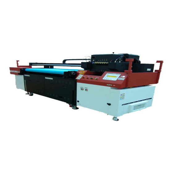
:ANAPURNA MV MODEL : :ANAPURNA MV MODEL : Exterior Appearance & Specification Exterior Appearance & Specification... - Page 16 ANAPURNA MV ANAPURNA MV FRONT VIEW FRONT VIEW Exterior Size (3,500mm*1,520mm*1,600mm) MAX PRINT WIDTH: 1,597mm...
- Page 17 :ANAPURNA MV :ANAPURNA MV FEATURE FEATURE □ Size (3,500mm*1,520mm*1,600mm) Max Print : 1.597mm □ UV Lamp Shutter System in accordance with printing signal. □ Auto lifting System : Max Media : 50mm □ High Resolution in Printing : KONICA HEAD INSTALLED ( KM512 / 14PL ) □...
- Page 18 :ANAPURNA MV :ANAPURNA MV SPECIFICATION SPECIFICATION Model :ANAPURNA MV Printing Technology DOD PIEZO ELECTRIC TECHNOLOGY Number of Print Head 6 HEADS [ KONICA / 512 / 14PL ] NORMAL MODE QUALITY MODE Print Speed 13-17 sqm/hr 6-10 sqm/hr 32BIT RISC...
- Page 19 :ANAPURNA MV :ANAPURNA MV BLOCK DIAGRAM BLOCK DIAGRAM...
- Page 20 INK SUPPLY FLOW DIAGRAM INK SUPPLY FLOW DIAGRAM SOLUTION BAR 3-WAY SOLUTION AIR FILTER VALVE MAIN TANK INK PUMP TANK FLOAT SENSOR Vacuum INK FILTER pressure device HEAD...
- Page 21 CODE STRIP CODE STRIP LM Rail Code Strip Home Sensor B/K The Print Resolution was improved by CODE STRIP (180 dpi)
- Page 22 STRUCTURE OF BOX BEAM STRUCTURE OF BOX BEAM Box Beam (R) Box Beam Shock LM Rail absorber Code Strip Home Sensor B/K Timing belt Easy Moving Carriage Structure in Box Beam (LM GUIDE 2EA USE)
- Page 23 STRUCTURE OF PLATEN STRUCTURE OF PLATEN Platen for Flat/Roll Type BAR for Origin Point Fixing Designed for easily using the Plate. (Origin Point Fix Air Cylinder attached)
- Page 24 STRUCTURE OF FRONT ROLL BAR STRUCTURE OF FRONT ROLL BAR ROLL BAR IN FRONT MEDIA...
- Page 25 STRUCTURE OF REAL ROLL BAR STRUCTURE OF REAL ROLL BAR The tension of media should be maintained equally with the roll bar in the rear.
- Page 26 STRUCTURE of CONTROL BOX STRUCTURE of CONTROL BOX The PCB assembled with three SUB PCBs was designed for easy to attach and detach.
- Page 27 :ANAPURNA MV MODEL : :ANAPURNA MV MODEL : 3. How to Use and List of Notice in Use 3. How to Use and List of Notice in Use...
- Page 28 GENERAL KEEPING (GENERAL LIST OF NOTICE) GENERAL KEEPING (GENERAL LIST OF NOTICE) 1. Keep the horizontality : Required for accurate printing Should be checked during the first installation in order to keep the printer in stable condition. 2. Maintain the grounding : Required for stable system maintenance. Should be checked during the first installation in order to keep the printer in stable system.
- Page 29 GENERAL KEEPING(GENERAL LIST OF NOTICE) GENERAL KEEPING(GENERAL LIST OF NOTICE) 5. Check the sensor sensitivity of MAIN TANK. 4. Check the Terminal of UV LAMP POWER. Check voltage/frequency(230V/60Hz) When ink is short, BUZZER beeps. A-1(203V/50Hz),A-2(203V/60Hz) B-1(230V/50Hz),B-2(230V/60Hz)
- Page 30 GENERAL KEEPING(GENERAL LIST OF NOTICE) GENERAL KEEPING(GENERAL LIST OF NOTICE) 6. Check INK FILTER 7. Check INK SUPPLYING HOSE After filling the ink into MAIN INK Check ink supplying hose for each TANK, deflate the air in the filter. color.
- Page 31 GENERAL KEEPING(GERNAL LIST OF NOTICE) GENERAL KEEPING(GERNAL LIST OF NOTICE) 8. Check the sensor in Waste Ink Tank 9. Check the SOLUTION TANK The message of Waste Full (purge) Check amount of solution in the tank of will be displayed on the LCD, and also MAIN/SUB SOLUTION.
- Page 32 GENERAL KEEPING(GENERAL LIST OF NOTICE) GENERAL KEEPING(GENERAL LIST OF NOTICE) 10. Check the voltage of CARRIAGE PCB. 11. Check the pressure in air tank. Check accurate setting of voltage at each Check the pressure of 4 ~6 kgf/㎠ head. in Air Tank.
-
Page 33: Servo Motor Driver
GENERAL KEEPING(GENERAL LIST OF NOTICE) GENERAL KEEPING(GENERAL LIST OF NOTICE) 12. Check the Parameter of SERVO 13. Check the Temperature controller. MOTOR DRIVER. Check the Temperature of SUB INK TANK(45C), HEADBASE(49C) & Check the value of FEED/CARRIAGE VANISH (40C). SERVO MOTOR DRIVER. - Page 34 GENERAL KEEPING(GENERAL LIST OF NOTICE) GENERAL KEEPING(GENERAL LIST OF NOTICE) 14. Beware of accurate ink supply for each color and ink spilling. Make sure not to confuse Magenta with Light Magenta, and Cyan with Light Cyan. Also please make sure SOLUTION and VANISH INK not to mix to use.
- Page 35 Alignment Alignment There are three ways for Alignment. - Head Alignment - Head Base Alignment - Lamp House Alignment Head Alignment 1) Control right & left slope of print head 2) Control up & down alignment of print head 3) Use two adjusting bolts and two fixing bolts. There are M3 bolt and fix bolt on both front side and back side.
- Page 36 Alignment Alignment 2) Alignment of Head Base 1) Control right & left alignment of head base. 2) Control front & rear alignment of head base. 3) Use two adjustment blocks. There is an adjustment block in the left and right side.
- Page 37 Alignment Alignment 3) Alignment of Lamp House 1) Control device for left, right alignment of Lamp House. 2) Use two adjusting bolts for the left, right control. Adjustment bolt in the Right & Left...
- Page 38 ABSOLUTELY KEEPING ABSOLUTELY KEEPING 1. Vacuum pressure checking: If the power of printer is on, the supply of compressed air should be available. (The value required for controlling each part should be aligned within the values written in the Sticker mentioned on each part.) 2.
- Page 39 LIST OF NOTICE WHEN TURNING THE POWER ON LIST OF NOTICE WHEN TURNING THE POWER ON 1. Dismantle all the power cables. (Shut down the Main Breaker.) 2. Verify the voltage short after dismantling all the cables. - Tester is adjusted at the position of measuring the resistance. When measuring the power cable and grounding, must have O.L value (unlimited).
- Page 40 ENCODER & CODE STRIP CHECK ENCODER & CODE STRIP CHECK Verify the status of red light on the encoder after turning the powder on. If CALIB. key is pressed down right after pressing down F2 Carriage Release, the carriage can be relocated by hand.
- Page 41 NEGATIVE PRESSURE CHECK NEGATIVE PRESSURE CHECK 1. Verify the operational condition of air compressor. 2. Verify the gauge of vacuum pressure. - Set the pressure value as written on the sticker. - If you got any trouble on vacuum pressure, it can cause series trouble for printing as falling-off of nozzle and ink dropping.
- Page 42 ASSENBLY & DISASSEMBLY OF CONVEYOR BELT ASSENBLY & DISASSEMBLY OF CONVEYOR BELT ① Separate the valve after removing ③ Insert the pin to the end. the ② Connect the belts by inserting a the pin linking between belts. remain section is fold and then pin between them.
- Page 43 TREE MENU TREE MENU HOST *** ***P S7 1597mm tcp K C M Y lC lM] MAIN F1> PRIME CLEANING IP/SET <F4 F2> UV LAMP/SHUTTER TAKE UP <F5 F3> HOME COVER PARAMETER <F6 F1> PRIME F2>UV LAMP/SHUTTER F3>HOME COVER F4>CLEANING F5>TAKEUP F6>PARAMETER OPEN/CLOSE...
- Page 44 TREE MENU TREE MENU == TEST == TEST F1> PRIME BELT TEST <F4 F2> PRIME 2(N,Q) DIR TEST(N,Q) <F5 F3> PRIME 2(F) DIR TEST(F) <F6 F1> PRIME F2>PRIME2 F3>PRIME2 F4>BELT TEST F5>DIR TEST F6>DIR TEST (N,Q) (N,Q) F1>RUN F2>STEP RUN F4>STOP PURGE == PURGE ==...
- Page 45 TREE MENU TREE MENU == CALIBRATION == F1> FEED ADJUST HORI. ADJUST <F4 CALIBRATION F2> CARRIAGE RELEASE DIR. ADJUST <F5 F3> FACTORY SETTING HEAD GAP <F6 F1>FEED F2>CARRIAGE F3>FACTORY F4>HORI. F5>DIR F6>HEAD ADJUST RELEASE SETTING ADJUST ADJUST F1>SERVO ON F2>PRINT VALUE F2>PRINT VALUE...
- Page 46 CONTROL PANEL CONTROL PANEL ON - LINE Key ON - LINE Indicator ESC Key F1 Key F2 Key F3 Key F4 Key F5 Key F6 Key TEST Key CALIB. Key PURGE Key CAPPING Key PAUSE Key ENTER Key UP Key DOWN Key LEFT Key RIGHT Key...
- Page 47 CONTROL PANEL CONTROL PANEL ON - LINE Key : Used to change the status of OFF LINE to that of ON LINE. ON - LINE Indicator : Light is on in ON-LINE MODE, if OFF, will shut down after showing up the data of print shortly. ESC Key : Use it when function is cancelled.
- Page 48 DECRIPTION OF OFF LINE MENU ( MAIN ) DECRIPTION OF OFF LINE MENU ( MAIN ) Operation of Each Function Key F1> PRIME: The function of PRIME is to check status of Nozzle Jetting and to get print-out in a decent quality F2>UV LAMP SHUTTER : In printing, set ON/OFF of LAMP, Mode of shutter (standard, 2 at a time), Delay distance of Lamp Shutter,...
- Page 49 SCRIPTION OF OFF LINE MENU ( UV LAMP/SHUTTER ) ESCRIPTION OF OFF LINE MENU ( UV LAMP/SHUTTER ) Operation of Each Function Key UP Key ,DOWN Key : Value Change LEFT Key ,RIGHT Key : Movement of Article ENTER Key : Terminate after saving. ESC Key : Terminate without saving.
- Page 50 ESCRIPTION OF OFF LINE MENU ( UV LAMP/SHUTTER ) ESCRIPTION OF OFF LINE MENU ( UV LAMP/SHUTTER ) Operation of each function key Delete : If entering 6142513 in the UV LAMP/SHUTTER MODE, the LCD window like left will be displayed. F1>...
- Page 51 ESCRIPTION OF OFF LINE MENU ( CLEANING / IP SET ) ESCRIPTION OF OFF LINE MENU ( CLEANING / IP SET ) Operation of each function key F1> HOME COVER : If pressing once, open. Then if pressing again, close F2>...
- Page 52 ESCRIPTION OF OFF LINE MENU ( CLEANING / IP SET ) ESCRIPTION OF OFF LINE MENU ( CLEANING / IP SET ) Operation of each function key UP Key ,DOWN Key : Value Change. ENTER Key : Terminate after saving. ESC Key : Terminate without saving.
- Page 53 DESCRIPTION OFF LINE MENU ( CLEANING / IP SET ) DESCRIPTION OFF LINE MENU ( CLEANING / IP SET ) After showing up the current firmware version for 3 second. It will return to SET MENU OF CLEANING/IP, previous mode. ANAPURNA M V1.246 TN6 Copyright 2007...
- Page 54 ESCRIPTION OF OFF LINE MENU ( CLEANING / IP SET ) ESCRIPTION OF OFF LINE MENU ( CLEANING / IP SET ) Operation of each function key UP Key ,DOWN Key : Value Change. LEFT Key ,RIGHT Key : Shift of item. ENTER Key : Terminate after saving.
- Page 55 ECRIPTION OF OFF LINE MENU ( CLEANING / IP SET ) ECRIPTION OF OFF LINE MENU ( CLEANING / IP SET ) Operation of each function key F1> BLACK : Jetting all the nozzles of black head. F2> CYAN : Jetting all the nozzles of CYAN head. F3>...
- Page 56 DESCRIPTION OF OFF LINE MENU ( CLEANING / IP SET ) DESCRIPTION OF OFF LINE MENU ( CLEANING / IP SET ) Operation of each function key UP Key ,DOWN Key : Value change. LEFT Key ,RIGHT Key : Shift of item. ENTER Key : Terminate after saving.
- Page 57 DESCRIPTION OF OFF LINE MENU ( TAKE UP ) DESCRIPTION OF OFF LINE MENU ( TAKE UP ) Operation of each function key UP Key ,DOWN Key : Value Change. LEFT Key ,RIGHT Key : Shift of Item. ENTER Key : Terminate after saving. ESC Key : Terminate without saving.
- Page 58 DESCRIPTION OF OFF LINE MENU ( PARAMETER ) DESCRIPTION OF OFF LINE MENU ( PARAMETER ) Operation of each function key UP Key ,DOWN Key : Value Change, LEFT Key ,RIGHT Key : Shift of item ENTER Key : Terminate after saving. ESC Key : Terminate without saving.
- Page 59 DESCRIPTION OF TEST MENU DESCRIPTION OF TEST MENU Operation of each function key F1 => PRIME: The function of PRIME is to lead the printing in good quality by checking whether the jetting of Nozzle is normal or not. F2 => PRIME 2(N,Q) : Print the PRIME Pattern of 360dpi in length Resolution.
- Page 60 DESCRIPTION OF TEST MENU DESCRIPTION OF TEST MENU Operation of each function key F1 => RUN : The conveyor belt is rotated forward. F4 =>STOP : Use it when stopping the rotation of conveyor. * The conveyor belt keeps rotated until pressing STOP. * Must press down ESC after pressing STOP <F4 * Otherwise, even if pressing down ESC, the belt will keep == BELT TEST ==...
- Page 61 DESCRIPTION OF CALIBRATION MENU DESCRIPTION OF CALIBRATION MENU Operation of each function key F1 => FEED ADJUST : Use it when checking or changing current feeding value. F2 => CARRIAGE RELEASE : Able to move the carriage by hand after servo-off. F3 =>...
- Page 62 DESCRIPTION OF CALIBRATION MENU DESCRIPTION OF CALIBRATION MENU Operation of each function key UP Key ,DOWN Key : Value Change ENTER Key : Terminate after saving ESC Key : Terminate without saving F2> PRINT : Print feeding pattern set in current feeding value. * The range of setting value is -50 upto 50.
- Page 63 DESCRIPTION OF CALIBRATION MENU DESCRIPTION OF CALIBRATION MENU Operation of each function key F1> SERVO ON And HOME CHECK : After Carriage is servo-on, do the HOME CHECK Then the carriage will be moved without changing the height of headbase, be cautious while in motion. == CARRIAGE RELEASE == F1>...
- Page 64 DESCRIPTION OF CALIBRATION MENU DESCRIPTION OF CALIBRATION MENU Operation of each function key Enter two different passwords in the entrance space of password First password is to access SYSTEM OPTION/TEST MENU. (PASSWORD: INPUT) The other password is to access FACTORY SETTING == CALIBRATION == MENU.
- Page 65 DESCRIPTION OF CALIBRATION MENU DESCRIPTION OF CALIBRATION MENU Operation of each function key F1> HORI. PRINT : Print the horizontal adjustment pattern in full size. F2> DIR PRINT(N,Q) : Print bi-direction pattern in 360dpi of horizontal resolution. F4> SYSTEM OPTION : Setting whether or not the use of == SYSTEM OPTION / TEST == HOME COVER while factory setting.
- Page 66 DESCRIOTION OF CALIBRATION MENU DESCRIOTION OF CALIBRATION MENU Operation of each function key UP Key ,DOWN Key : Value Change ENTER Key : Terminate after saving ESC Key : Terminate without saving HOME COVER = ON,OFF : If HOME COVER is air cylinder type, and only if sensor is attached, set ON.
- Page 67 DESCRIPTION OF CALIBRATION MENU DESCRIPTION OF CALIBRATION MENU Impossible to change if marking in here. Temp : Display current temperature of each head. LEFT: The currently permitted voltage is displayed in the left column of each head RIGHT: The currently permitted voltage is displayed In the right column of each head.
- Page 68 DESCRIPTION OF CALIBRATION MENU DESCRIPTION OF CALIBRATION MENU If entering password (1643259) that can access to FACTORY SETTING MODE, the contents like shown in the left LCD screen will be displayed. Operation of each function key F1> HEAD ADJUST : It is the mode for adjusting HEAD ALIGMENT ANGLE.
- Page 69 DESCRIPTION OF CALIBRATION MENU DESCRIPTION OF CALIBRATION MENU Operation of each function key F1> PRINT: Print the pattern of HEAD ALIGNMENT ANGLE. F5> ADJUST END: Use it when ending HEAD ALINMENT. ESC : Use it when ending HEAD ALIGNMENT. == HEAD ADJUST (ANGLE) == F2>...
- Page 70 DESCRIPTION OF CALIBRATION MENU DESCRIPTION OF CALIBRATION MENU Operation of each function key UP Key, DOWN Key : Value Change LEFT Key, RIGHT Key : Shift of time ENTER Key : Terminate after saving ESC Key : Terminate without saving == Head Voltage Adjust == * After checking the label stuck on the head, LEFT...
- Page 71 DECRIPTION OF CALIBRATION MENU DECRIPTION OF CALIBRATION MENU It is the mode for adjusting REFERENCE VOLTAGE of CARRIGE PCB. Matching the LOW and HIGH of standard voltage in the left and right channel to 15V and 7.5V by changing variable resistance. →...
- Page 72 DESCRIPTION OF CALIBRATION MENU DESCRIPTION OF CALIBRATION MENU Operation of each function key UP Key ,DOWN Key : Value Change LEFT Key ,RIGHT Key : Shift of item ENTER Key : Terminate after saving ESC Key : Terminate without saving PRINT ORIGIN(mm) = -50 upto 50 : Decide position of printing 0 point == SYSTEM REFERENCE ==...
- Page 73 DESCRIPTION OF CALIBRATION MENU DESCRIPTION OF CALIBRATION MENU It is impossible to change if making a mark in here. Temp : Display the current temperature of each head. LEFT: Display the permitted voltage in the left column of each head RIGHT: Display the permitted voltage in the right Temp.
- Page 74 DESCRIPTION OF CALIBRATION MENU DESCRIPTION OF CALIBRATION MENU Operation of each function key UP Key ,DOWN Key : Value Change ENTER Key : Terminate after saving ESC Key : Terminate without saving . F2> PRINT : Print feeding pattern set in current feeding value.
- Page 75 DESCRIPTION OF CALIBRATION MENU DESCRIPTION OF CALIBRATION MENU Operation of each function key UP Key ,DOWN Key : Value Change ENTER Key : Terminate after saving ESC Key : Terminate without saving F2> PRINT : Print feeding pattern set in current feeding value. F4>...
- Page 76 DESCRIPTION OF CALIBRATION MENU DESCRIPTION OF CALIBRATION MENU Operation of each function key LEFT Key , RIGHT Key : The carriage is moved to left, right of HEAD MOVE. Move to left 10 times. UP Key , DOWN key : GAP Value Change F6 =>...
- Page 77 DESCRIPTION OF CALIBRATION MENU DESCRIPTION OF CALIBRATION MENU Operation of each function key LEFT Key , RIGHT Key : The carriage is moved to left, right of HEAD MOVE. Move to left 10 times. UP Key , DOWN key : REFERENCE Value Change = = HEAD GAP REFERENCE = = F6 =>...
- Page 78 DESCRIPTION OF CALIBRATION MENU DESCRIPTION OF CALIBRATION MENU * Order of Operation * Keep pressing down <-- until the head reaches to Top. And then move it to left. Press several times in order to move the carriage to the position in which you want to measure. If pressing down the ENTER Key, L bracket is down, and the Head is also down with rotating stepping motor.
- Page 79 DESCRIPTION OF PURGE MENU DESCRIPTION OF PURGE MENU Operation of each function key F1 : Run the head capping. F2 : Run the SUCTION. == PURGE == F1> CAPPING F2> SUCTION...
- Page 80 DESCRIPTION OF PURGE MENU DESCRIPTION OF PURGE MENU Once the carriage reaches the highest position, the bracket in L type is moved down. After the carriage is lowered and after the Bracket in L type senses the cover of capping, the bracket again is moved up.
- Page 81 DESCRIPTION OF PURGE MENU DESCRIPTION OF PURGE MENU Once the carriage reaches the highest position, the bracket in L type is moved down. After the Bracket in L type senses the cover of capping, the bracket again is moved up. After the carriage stops, the carriage again moves down to the capping pad and adhered closely.
- Page 82 DESCRIPTION OF PURGE MENU DESCRIPTION OF PURGE MENU Operation of each function key F1 : Run the head capping. F2 : Run the SUCTION. == CALIBRTION == F2> HEAD VOLTAGE CALIBRATION F3> HEAD VOLTAGE SETTING...
- Page 83 DESCRIPTION OF PURGE MENU DESCRIPTION OF PURGE MENU It is the mode to adjust REFERENCE VOLTAGE OF CARRIGE PCB. By changing the variable resistance, match Low & High Standard Voltage in the left and right channel to 15V and 7.5V *PCB Voltage Adjustment <H/W>...
- Page 84 DESCRIPTION OF PURGE MENU DESCRIPTION OF PURGE MENU Operation of each function key UP Key, DOWN Key : Value Change LEFT Key, RIGHT Key : shift of item ENTER Key : Terminate after saving ESC Key : Terminate without saving == Head Voltage Adjust == * Set the voltage higher than 3.2V by checking the LEFT...
- Page 85 DESCRIPTON OF CAPPING MENU DESCRIPTON OF CAPPING MENU After moving the carriage to purge direction. Carrying out the function of capping shortly. If you want either to turn off the power or to cancel the capping, Press down ESC key. == CAPPING = UNCAPPING<...
- Page 86 IMAGE PRINTING OUT (PRINT) IMAGE PRINTING OUT (PRINT) PRESS HOST UNI Q4P S7 1597mm [K C M Y lC lM] PRINTING 10 /100 (10%) 1. Once pressing ON-LINE Button, transfer the image file to be output from RIP. (In the RIP program, in case of RIP AND PRINT, RIP will be also printed out.) 2.
- Page 87 CANCELLATION OF PRINTING CANCELLATION OF PRINTING PRESS HOST UNI Q4P S7 1597mm [K C M Y lC lM] PRINTING 10 /100 (10%) CANCLE ? (Y:ENTER / N:ESC) 1. After pressing down ESC in the Keyboard, if selecting the ENTER button, the printing will be cancelled.
- Page 88 SELECT SWITCH SELECT SWITCH 1. Lamp Control<Left, Right> 1)MODE: OFF, LO, HI 3 OFF: In the OFF position, can not turn Lamp on. LO : In the LO position, Lamp work as LO. HI : In the HI position, Lamp work as HI. ※...
- Page 89 SELECT SWITCH SELECT SWITCH ⇒ DELY(ON/OFF) 20/20 DELY (ON/FFF) means that the shutter will be turned ON 20cm right from location of Image and OFF 20cm left from the location of image. Unit is (㎝). Able to set between 0 and 99㎝. ※...
- Page 90 CHECKING LIST RELATED TO POWER CHECKING LIST RELATED TO POWER 1. Cut off MAIN BRAKER. 2. Check the power short in the OFF state of all the brakers. - The resistance between power source and grounding: O.L is normal. 3. Check all the short situation with equipment including AC Line and chassis. 4.
- Page 91 ENCORDER CHECKING ENCORDER CHECKING 1. Press CALIB button. 2. Press Key of F2> CARRIAGE SELEASE. 3. Move the carriage slowly to the right or the left by hand. 4. Check the ON/OFF of ENC A, ENC B LED for HEAD PCB. 5.
- Page 92 Check of Negative Pressure Check of Negative Pressure 1. Check the movement of COMPRESSOR. 2. Check the pressure in the vacuum pressure gauge - Setting with pressure value indicated in the sticker for each part. - If the negative pressure do not match, the serious problem like nozzle exclusion, ink dropping etc may occur.
- Page 93 :ANAPURNA MV MODEL : :ANAPURNA MV MODEL : 4. ABNORMAL PRINTING/DECLINE OF PRINTING QUALITY 4. ABNORMAL PRINTING/DECLINE OF PRINTING QUALITY...
- Page 94 PRINTING ERROR PRINTING ERROR No Printing Image – Encoder error Cleaning of Code Strip (Use clean cloth) Check the gap between Encoder and Code Strip. Check the status of ON/OFF of LED for Encoder A.B of HEAD PCB Check the angle between encoder and code strip.
- Page 95 POOR PRINTING QUALITY POOR PRINTING QUALITY 1. Check the negative air pressure: Regulating within the range of graduation in the sticker of each part. 2. Check the voltage of head jetting : Check and regulate each head voltage. 3. CALIBRATION CHECKING (BI, FEED) 4.
- Page 96 OVERFLOW OF INK OVERFLOW OF INK 1. Verify the ink filter in the refill area. (main reason to overflow) - Should remove the air in the air filter. 2. Error of level sensor in sub-ink tank. 3. Error in negative pressure and connecting tube. (Check the gauge of negative pressure in -0.028 ~ -0.038kgf/ ㎠) 4.
- Page 97 :ANAPURNA MV MODEL : :ANAPURNA MV MODEL : 5. DRIVER PARAMETER 5. DRIVER PARAMETER...
- Page 98 TEMPERTURE CONTROLLER SETTING ※ Please refer the homepage of Autonic for below contents. ▣ Name of each part (TZ4ST) How to Set and Change the Setting Value (SV) ※ The scope of temperature regulation is set for 0~ 45 ℃ originally. 1) Switch on the power of heater controller.
- Page 99 2) Press << key to move to next digit on the left 3) Press UP and Down keys to change the value during blinking. 4) Press the MD key when you have finished the temperature setting. It will stop blinking. ※...
- Page 100 DESCRIPTION OF DRIVER PARAMETER OF SERVO MOTOR -1 Customer setting NO. Symbol Name and Function Initial Value Unit Feed Carriage *STY Command system/regenerative brake option selection 0000 0010 0310 *FTY Feeding function selection 0000 0011 0010 *OP1 Function selection 1 0002 0002 0002...
- Page 101 DESCRIPTION OF DRIVER PARAMETER OF SERVO MOTOR-2 *OP2 Function selection 0000 0000 0000 For manufacturer setting 0002 0002 0002 *OP4 Function selection 0000 0000 0000 Serial communications time-out selection Feed forward gain % Override offset Torque limit offset *ENR Encoder output pulses 4000 pulse/rev 4000...
- Page 102 DESCRTION OF DIRVER PARAMETER OF SERVO MOTOR-3 STM ㎛ *LMP Software limit + ×10 STM ㎛ *LMN Software limit - ×10 STM ㎛ *LPP Position range outpot address + ×10 STM ㎛ *LNP Position range outpot address - ×10 For manufacturer setting 0000 0000 0000...
- Page 103 DESCRITION OF DRIVER PARAMETER OF SERVO MOTOR-4 Gain changing time constant For manufacturer setting 10000 10000 10000 OUT1 OUT1 output time selection 10ms OUT2 OUT2 output time selection 10ms OUT3 OUT3 output time selection 10ms *SYC1 Selected to program input polarity selection 0000 0001 0000...
- Page 104 ERROR TABLE OF SERVO MOTOR DRIVER -1...
- Page 105 ERROR TABLE OF SERVO MOTOR DRIVER - 2...
- Page 106 ERROR TABLE OF SERVO MOTOR DRIVER -3...
- Page 107 ERROR TABLE OF SERVO MOTOR DRIVER -4...
- Page 108 ERROR TABLE OF SERVO MOTOR DRIVER -5...
- Page 109 ERROR TABLE OF SERVO MOTOR DRIVER -6...
- Page 110 ERROR TABLE OF SERVO MOTOR DRIVER -7...
- Page 111 ERROR TABLE OF SERVO MOTOR DRIVER -8...
- Page 112 ERROR TABLE OF SERVO MOTOR DRIVER -9...
- Page 113 ERROR TABLE OF SERVO MOTOR DRIVER -10...
- Page 114 ERROR TABLE OF SERVO MOTOR DRIVER -11...
- Page 115 ERROR TABLE OF SERVO MOTOR DRIVER -12...
- Page 116 ERROR TABLE OF SERVO MOTOR DRIVER - 13...
- Page 117 ERROR TABLE OF SERVO MOTOR DRIVER -14...
- Page 118 ERROR TABLE OF SERVO MOTOR DRIVER -15...
- Page 119 ERROR TABLE OF SERVO MOTOR DRIVER -16...
- Page 120 ERROR TABLE OF SERVO MOTOR DRIVER -17...
-
Page 121: Electric Diagram/Pcb Description
:ANAPURNA MV MODEL : :ANAPURNA MV MODEL : 6.ELECTRIC DIAGRAM/PCB 6.ELECTRIC DIAGRAM/PCB DESCRIPTION DESCRIPTION... - Page 122 TOTAL ELECTRONIIC SYSTEM CIRCUIT DIAGRAM TOTAL ELECTRONIIC SYSTEM CIRCUIT DIAGRAM * Bigger original circuit diagram is attached for understanding.
- Page 123 POWER BOX ELECTRIC SYSTEM WIRING DIAGRAM POWER BOX ELECTRIC SYSTEM WIRING DIAGRAM * Bigger original circuit diagram is attached for understanding.
- Page 124 SWITCHBOARD SWITCHBOARD...
- Page 125 SWITCHBOARD DESCRIPTION OF EACH PART SWITCHBOARD DESCRIPTION OF EACH PART – – Input terminal block for main power Initial short circuit breaker, MCCB, Main short circuit breaker Noise filter If Main MC-START button is pressed, begin to work. short circuit breaker(MCCB) – UV Lamp, Motor driver power, Ring blower, Controller rack.
- Page 126 LAMP POWER SYSTEM CIRCUIT DIAGRAM LAMP POWER SYSTEM CIRCUIT DIAGRAM * Bigger original circuit diagram is attached for understanding.
- Page 127 UV LAMP AND LMAP CASE 85, 120w/cm...
- Page 128 UV LAMP – PART DESCRIPTION Lamp power connector (4P) Lamp Signal Connector (7P) Lamp shutter signal connector(2P) Lamp shutter closing air compressor tube. Lamp shutter opening air compressor tube Lamp House Exhaust DC FAN Lamp case induction AC FAN...
- Page 129 NAME OF EACH PART FOR LAMP POWER Air penetration hole Indicator light for Lamp status Right Lamp Connector AC fuse holder Left Lamp Connector DC fuse holder...
- Page 130 INNER STRUCTURE OF LAMP POWER...
- Page 131 HOW TO SET POWER LAMP Power Input Voltage Tap Setting (ex: 220V, 60Hz.) DESCRIPTION OF TAB Power 204V 230V 50Hz 60Hz Frequency...
- Page 132 DIAGRAM – TROUBLE CHECK CHART * Bigger original circuit diagram is attached for understanding.
- Page 133 INK SUPPLY FLOW DIAGRAM INK SUPPLY FLOW DIAGRAM SOLUTION BAR 3-WAY SOLUTION AIR FILTER VALVE MAIN TANK INK PUMP TANK FLOAT SENSOR Air Compression INK FILTER device HEAD...
- Page 134 DIAGRAM MAIN INK SUPPLY PART DIAGRAM MAIN INK SUPPLY PART – – 1. Main Refill Motor 2. Refill motor 3. Ink Filter 4. Ink Hose Fixing part, up, down 6. Solution Mini Valve 7. Head 5. Sub Ink Tank...
- Page 135 DIAGRAM Pneumatic flow chart&circuit DIAGRAM Pneumatic flow chart&circuit – – * Bigger original circuit diagram is attached for understanding.
- Page 136 DIAGRAM KEY PART OF AIR COMPRESSION (1) DIAGRAM KEY PART OF AIR COMPRESSION – – Inlet port of main air compression Main Regulator Scale (0.4~0.6MPa) Lamp Shutter Regulator Scale (0.1MPa) Air Filter Regulator #2 Scale.(0.1MPa) Water Drain Hose SUCTION VACUUM EJECTOR SUCTION SOLENOID...
- Page 137 DIAGRAM KEY PARTS OF AIR COMPRESSION (2) DIAGRAM KEY PARTS OF AIR COMPRESSION (2) – – Sub Air Tank and Ink Reverse Tank Drain valve when overflowing Lamp shutter solenoid valve Carriage #4 ITV2010(Electro-Pneumatic Regulator) VT301, when purging, “on” operate ZM072H(Vacuum Ejector)
- Page 138 DIAGRAM KEY PARTS OF AIR COMPRESSION (3) DIAGRAM KEY PARTS OF AIR COMPRESSION (3) – – PURGE S/W 1. Purge Switch 2. Regulator of Air Compression (0.03MPa)
- Page 139 TOTAL SYSTEM DIAGRAM TOTAL SYSTEM DIAGRAM * Bigger original circuit diagram is attached for understanding.
- Page 140 TOTAL PCB LAYOUT TOTAL PCB LAYOUT * Bigger original circuit diagram is attached for understanding.
- Page 141 PCB LIST PCB LIST PCB LIST 1. MAIN PCB (UVM-03) P.143 2. NETSUB PCB (UVN-03) P.152 3. HEAD PCB (UVH-03) P.160 4. REFILL PCB (UVR-03) P.169 5. CARTRIDGE PCB #1 ~ #4 (UVC-03) P.177 6.HEAD LIFT PCB (UVL-01) P.192 7. SUB PCB (UVS-03) P.198 8.
- Page 142 – – Main + NET SUB PCB MAIN FUNCTION 1. It process print data received from sub-net PCB and transfer it to HEAD PCB. 2. All kinds of device is controlled by communicating Thru SUB PCB#2 and Core Cable. 3. Receive operation power supplied thru HEAD PCB. Part #;...
- Page 143 Main PCB MAIN FUNCTION 1. It process print data received from sub-net PCB and transfer it to HEAD PCB. 2. All kinds of device is controlled by communicating Thru SUB PCB#2 and 15P Core Cable 3. Receive operation power supplied thru HEAD PCB. Part #;...
- Page 144 Main PCB CONNECTOR CONNECTION MAP 1. J1 Disconnection J2 2X45 (1.27 Arrangement) --> Net Sub JP1 J3 2X50 (1.27 Arrangement) --> Net Sub JP2 J4 Disconnection J5 Disconnection JP1 Disconnection JP2 HRS-PCN10-64P-254DSA --> Head J15 JP3 D-SUB 15(FEMALE) --> Sub #2 J23 Part #;...
- Page 145 MAIN PCB IO MAP * Bigger original circuit diagram is attached for understanding.
- Page 146 MAIN IO MAP-1 HEAD PCB HO ME 1 VDD5V HO ME SENSO R PCB 1 VDD5V(RED) 5045-3P 2 SEN-HOME 5051-3P 2 SEN-HOME-OUT(YELLOW) 3 GND 3 GND(BLACK) 1 SIGNAL(BLACK) FLO AT SENSO R, K 1 SIGNAL K(BLACK) 5268-2P 2 GND (BLACK) 5264-2P 2 GND(BLACK) ENCO DER...
- Page 147 MAIN IO MAP-2 5 L h DATA1 5 L h DATA1 6 R h DATA1 6 R h DATA1 7 L h DATA2 7 L h DATA2 8 R h DATA2 8 R h DATA2 9 L h DATA3 9 L h DATA3 10 R h DATA3 10 R h DATA3 11 L h DATA4...
- Page 148 MAIN IO MAP-3 57 INKL 7 57 INKL 7 58 INKL 8 58 INKL 8 59 GND 59 GND 60 GND 60 GND 61 N.C 61 N.C 62 N.C 62 N.C 63 N.C 63 N.C 64 N.C 64 N.C INK_K 1 VH-POW CARTRIDGE PCB, J7 1 GND...
- Page 149 MAIN IO MAP-4 13 AD1(C) 13 L-DAT0 14 GND 14 GND 15 VDD5V 15 VDD5V 16 VDD5V 16 VDD5V 17 GND 17 GND 18 L-DAT0(C) 18 AD1 19 R-DAT0(C) 19 DA2 20 L-DAT1(C) 20 DA1 21 L-DAT1(C) 21 DP2L 22 CLK 22 DP2H 23 LAT 23 DP1L...
- Page 150 MAIN IO MAP-5 straight Ty pe 3 VH-POW 3 STBCL 4 GND 4 LOAD 5 DC12V 5 STB3 6 GND 6 STB2 7 DP1H 7 STB1 8 DP1L 8 LAT 9 DP2H 9 CLK 10 DP2L 10 R-DAT1 11 DA1(Y) 11 L-DAT1 12 DA2(Y) 12 R-DAT0...
- Page 151 MAIN IO MAP-6 17 GND 17 GND 18 L-DAT0(LC) 18 AD1 19 R-DAT0(LC) 19 DA2 20 L-DAT1(LC) 20 DA1 21 L-DAT1(LC) 21 DP2L 22 CLK 22 DP2H 23 LAT 23 DP1L 24 STB1 24 DP1H 25 STB2 25 GND 26 STB3 26 DC12V 27 LOAD 27 GND...
- Page 152 – – NET SUB PCB MAIN FUNCTION Connected with Main PCB. Either transfer output data received thru LAN port or be used when updating files. Part #; UVN-03...
- Page 153 – – NET SUB PCB CONNECTOR CONNECTION MAP U3 UTP CABLE ---> LAN CABLE JP1 2X45 (1.27 Arrangement) --> Main J2 JP2 2X50 (1.27 Arrangement) --> Main J3 Part #; UVN-03...
- Page 154 – – NET SUB PCB IO MAP * Bigger original circuit diagram is attached for understanding.
- Page 155 – – NET SUB IO MAP-1 NET_ SUB 1 TD+ TPTX+ GORE CABLE RJ45 1 − 2 TD- TPTX- LAN UTP CABLE 2 − 3 TCT (LAN) 3 − 4 NC1 4 N.C 5 NC2 5 N.C 6 RCT 6 − 7 RD+ TPRX+ 7 N.C 8 RD- TPRX-...
- Page 156 – – NET SUB IO MAP-2 26 A11 26 DATA11 27 N.C 27 A12 28 A12 28 DATA12 29 N.C 29 A13 30 A13 30 DATA13 31 N.C 31 A14 32 A14 32 DATA14 33 N.C 33 A15 34 N.C 34 DATA15 35 N.C 35 A16...
- Page 157 – – NET SUB IO MAP-3 68 n RESET 68 NXDREQ0 69 N.C 69 NRSTOUT 70 N.C 70 NXDACK0 71 N.C 71 NWAIT 72 N.C 72 NXDREQ1 73 N.C 73 CLKOUT0 74 N.C 74 NXDACK1 75 N.C 75 OLKOUT1 76 N.C 76 BATTFLT 77 N.C 77 EXTCLK...
- Page 158 – – NET SUB IO MAP-4 19 N.C 19 GPD0 20 N.C 20 GPJ8 21 N.C 21 GPD1 22 N.C 22 GPJ9 23 N.C 23 GPD2 24 N.C 24 GPJ10 25 N.C 25 GPD3 26 N.C 26 GPJ11 27 N.C 27 GPD4 28 N.C 28 GPJ12...
- Page 159 – – NET SUB IO MAP-5 61 N.C 61 GPA20 62 N.C 62 GPG5 63 N.C 63 GPA22 64 N.C 64 GPG6 65 N.C 65 HCON 66 N.C 66 GPG7 67 N.C 67 FRNB 68 N.C 68 NSS_KBD 69 N.C 69 LOGIC_EN 70 N.C 70 NDIS_OFF...
- Page 160 HEAD PCB Main Function Connected with Main PCB, send the signal for ink supply by transferring the signal received from each sub Ink Tank. Send output data received by connecting with each cartridge PCB. Receive Floating signal from each ink tank.
- Page 161 HEAD PCB CONNECTOR CONNECTION MAP J1 5045-3 --> HOME SENSOR PCB J2 5268-2 --> SENSOR K J3 GIL-G4A --> ENCODER J4 5268-2 --> SENSOR C J5 5268-2 --> SENSOR M J6 5268-2 --> SENSOR Y J7 5268-4 --> SIZE SENSOR J8 5268-2 -->...
- Page 162 HEAD PCB IO MAP * Bigger original circuit diagram is attached for understanding.
- Page 163 HEAD IO MAP-1 HEAD PCB HO ME 1 VDD5V HO ME SENSO R PCB 1 VDD5V(RED) 5045-3P 2 SEN-HOME 5051-3P 2 SEN-HOME-OUT(YELLOW) 3 GND 3 GND(BLACK) 1 SIGNAL(BLACK) FLO AT SENSO R, K 1 SIGNAL K(BLACK) 5268-2P 2 GND (BLACK) 5264-2P 2 GND(BLACK) ENCO DER...
- Page 164 HEAD IO MAP-2 5 L h DATA1 5 L h DATA1 6 R h DATA1 6 R h DATA1 7 L h DATA2 7 L h DATA2 8 R h DATA2 8 R h DATA2 9 L h DATA3 9 L h DATA3 10 R h DATA3 10 R h DATA3 11 L h DATA4...
- Page 165 HEAD IO MAP-3 57 INKL 7 57 INKL 7 58 INKL 8 58 INKL 8 59 GND 59 GND 60 GND 60 GND 61 N.C 61 N.C 62 N.C 62 N.C 63 N.C 63 N.C 64 N.C 64 N.C INK_K 1 VH-POW CARTRIDGE PCB, J7 1 GND...
- Page 166 HEAD IO MAP-4 13 AD1(C) 13 L-DAT0 14 GND 14 GND 15 VDD5V 15 VDD5V 16 VDD5V 16 VDD5V 17 GND 17 GND 18 L-DAT0(C) 18 AD1 19 R-DAT0(C) 19 DA2 20 L-DAT1(C) 20 DA1 21 L-DAT1(C) 21 DP2L 22 CLK 22 DP2H 23 LAT 23 DP1L...
- Page 167 HEAD IO MAP-5 straight Ty pe 3 VH-POW 3 STBCL 4 GND 4 LOAD 5 DC12V 5 STB3 6 GND 6 STB2 7 DP1H 7 STB1 8 DP1L 8 LAT 9 DP2H 9 CLK 10 DP2L 10 R-DAT1 11 DA1(Y) 11 L-DAT1 12 DA2(Y) 12 R-DAT0...
- Page 168 HEAD IO MAP-6 17 GND 17 GND 18 L-DAT0(LC) 18 AD1 19 R-DAT0(LC) 19 DA2 20 L-DAT1(LC) 20 DA1 21 L-DAT1(LC) 21 DP2L 22 CLK 22 DP2H 23 LAT 23 DP1L 24 STB1 24 DP1H 25 STB2 25 GND 26 STB3 26 DC12V 27 LOAD 27 GND...
- Page 169 REFILL PCB MAIN FUNCTION Connected to both SUB PCB 2 and Communication port. Control each ink pump By connecting with CONTROL PCB. Send and receive the status of Ink and Ink supplying and signal of ink supplying By checking the remained ink in the Main Ink Tank, Sound Biff buzzer if ink is short.
- Page 170 REFILL PCB CONNECTOR CONNECTION MAP J1 B2P-VH --> Pump LC J2 5267-3 --> Level Sensor M J3 B2P-VH --> Pump M J4 5267-3 --> Level Sensor K J5 B2P-VH --> Pump K J6 5267-3 --> Level Sensor LC J8 Disconnection J10 5566-2 -->...
- Page 171 REFILL PCB IO MAP * Bigger original circuit diagram is attached for understanding.
- Page 172 REFILL IO MAP-1 REFILL PUMP_LC 1 INK_PUMP_LC(BROWN) INK PUMP LC MOTOR - B2P-VH 2 DC24V(GREEN) MOTOR + TANK_M 1 GND TANK M Lev el sensor BLACK COMMON 5267-3P 2 E_TANK_M EMPTY SENSOR 3 F_TANK_M YELLOW FULL SENSOR PUMP_M 1 INK_PUMP_M(BROWN) INK PUMP M MOTOR - B2P-VH...
- Page 173 REFILL IO MAP-2 TAKE-F-SEN 1 TAKE-F-SEN(BLACK) BROWN DC24V AUTONICS, PHOTOSENSOR 5566-4P 2 GND(BLUE) BLACK SENSOR OUT 3 N.C BLUE 4 DC24V(BROWN) TAKE_R_SEN 1 DC24V(BROWN) AUTONICS, PHOTOSENSOR BROWN DC24V 5219-3P 2 TAKE-R-SEN(BLACK) BLACK SENSOR OUT 3 GND(BLUE) BLUE RS_REFILL 1 RX REFILL SUB J9 (TAKEUP/REFILL) 1 +5V 5267-3P...
- Page 174 REFILL IO MAP-3 SO L_PUMP 1 INK_PUMP_SOL(BROWN) INK PUMP SO L MOTOR - B2P-VH 2 DC24V(WHITE) MOTOR + TANK_Y 1 GND TANK_Y Lev el sensor BLACK COMMON 5267-3P 2 E_TANK_Y EMPTY SENSOR 3 F_TANK_Y YELLOW FULL SENSOR TANK_C 1 GND TANK_C Lev el sensor BLACK COMMON...
- Page 175 REFILL IO MAP-4 O VERFLO W 1 +5V NOT USED 5267-2P 2 OVER_FLOW NOT USED CO NTRO L 1 SW_Y CO NTO RL J18 1 SW_Y HIF3BA30DS A 2 SW_M HIF3BA30DS 2 SW_M 3 SW_C 3 SW_C 4 SW_K 4 SW_K 5 SW_LM 5 SW_LM 6 SW_LC...
- Page 176 REFILL IO MAP-5 MAIN_ ERRO R 1 MAIN_ERROR NOT USED 5267-3P 2 N.C NOT USED 3 GND NOT USED S O L_ VALVE 1 SOL_VALVE NOT USED B2P-VH 2 DC24V NOT USED BUZZER 1 GND DC5V용 BUZZER BLACK BUZZER - 5267-4P 4 BUZZER BUZZER +...
- Page 177 – – CARTRIDGE#1 PCB MAIN FUNCTION Connected with Signal connector Coming from HEAD PCB. Part #; UVC-03...
- Page 178 – – CARTRIDGE#1 PCB CONNECTOR CONNECTION MAP J7 5597-30 Straight --> Head J16 K --> Head J17 C --> Head J18 M --> Head J19 Y --> Head J21 LC --> Head J22 LM Part #; UVC-03...
- Page 179 – – CARTRIDGE#1 PCB IO MAP * Bigger original circuit diagram is attached for understanding.
- Page 180 – – CARTRIDGE IO MAP-1 Cartri dge PCB Head PCB 1 GND 1 VH-POW 5597-30P 2 GND 5597-30P 2 VH-POW straight Type 3 STBCL straight Type 3 VH-POW 4 LOAD 4 GND 5 STB3 5 DC12V 6 STB2 6 GND 7 STB1 7 DP1H 8 LAT...
- Page 181 – – CARTRIDGE IO MAP-2 1 VH Print Head 1 VH 5077-50P 2 N.C 2 N.C Receptacle 3 N.C 3 N.C 4 R-COM24 4 R-COM24 5 R-COM24 5 R-COM24 6 R-COM24 6 R-COM24 7 R-COM13 7 R-COM13 8 GND 8 GND 9 R-COM13 9 R-COM13 10 L-SI1...
- Page 182 – – CARTRIDGE IO MAP-3 34 L-STB1 34 L-STB1 35 VDD5V 35 VDD5V 36 L-STB2 36 L-STB2 37 TH 37 TH 38 L-STB3 38 L-STB3 39 R-SI1 39 R-SI1 40 R-SI0 40 R-SI0 41 GND 41 GND 42 L-COM13 42 L-COM13 43 L-COM13 43 L-COM13 44 L-COM13...
- Page 183 – – CARTRIDGE#2 PCB MAIN FUNCTION Voltage Control Terminal for left side channel. (TP1, TP2) Voltage Control Volume for left side channel. (VR1, VR2) Left Channel Signal Process. Part #; UVC-03...
- Page 184 – – CARTRIDGE#2 PCB CONNECTOR CONNECTION MAP JP1 : (RED) LEFT CHANNEL HIGH 15.00V Setting terminal. JP2 : (YEL) LEFT CHANNEL LOW 7.50V Setting terminal. JP3 : (BLACK) GND TERMINAL. VR1 : (LH) LEFT CHANNEL HIGH 15.00V Setting volume. VR2 : (LL) LEFT CHANNEL LOW 7.50V Setting volume.
- Page 185 – – CARTRIDGE#2 PCB IO MAP * Bigger original circuit diagram is attached for understanding.
- Page 186 – – CARTRIDGE#3 PCB MAIN FUNCTION 1. Voltage Control Terminal for Right side channel. (TP1, TP2) 2. Voltage Control Volume for Right side channel. (VR31, VR4) 3. Right Channel Signal Process. Part #; UVC-03...
- Page 187 – – CARTRIDGE#3 PCB CONNECTOR CONNECTION MAP JP4 : (RED) RIGHT CHANNEL HIGH 15.00V SETTING TERMINAL JP5 : (YEL) RIGHT CHANNEL LOW 7.50V SETTING TERMINAL. JP6 : (BLA) GND TERMINAL. VR3 : (RH) RIGHT CHANNEL HIGH 15.00V SETTING VOLUME VR4 : (RL) RIGHT CHANNEL LOW 7.50V SETTING VOLUME Part #;...
- Page 188 – – CARTRIDGE#3 PCB IO MAP * Bigger original circuit diagram is attached for understanding.
- Page 189 – – CARTRIDGE#4 PCB MAIN FUNCTION Connected with Konica HEAD Part #; UVC-03...
- Page 190 – – CARTRIDGE#4 PCB CONNECTOR CONNECTION MAP J7 5077-50 Receptacle --> Print Head K --> Print Head C --> Print Head M --> Print Head Y --> Print Head LC --> Print Head LM Part #; UVC-03...
- Page 191 – – CARTRIDGE#4 PCB IO MAP * Bigger original circuit diagram is attached for understanding.
- Page 192 HEAD LIFT PCB Main Function 1. Connect Step Motor Connector with Headbase spring PCB1. 2. Transfer Input Signal of both Headbase temperature sensor and Sub-Ink temperature sensor to I/F PCB. 3. Receive the signal pf Headbase Header and sub ink tank heater from I/F OCB. 4.
- Page 193 HEAD LIFT PCB CONNECTOR CONNECTION MAP J1 5045-5 --> UP/DOWN Photo Sensor Omron J3 Disconnection J4 GIL-G4 --> Sub#2 J25 J6 B5P-VH --> VT301/VT301V 3Ways Sol Valve J7 5045-9 --> I/F J2 J8 B6P-VH --> I/F J1 J10 5267-3 --> Temperature Sensor in Sub Ink Tank J11 Disconnection J12 B2P-VH -->...
- Page 194 HEAD LIFT PCB IO MAP * Bigger original circuit diagram is attached for understanding.
- Page 195 HEAD LIFT IO MAP-1 HEAD BASE LIFT LIMIT_ SEN 1 GND(BLACK) SEN DO W N 1 +(RED) 5045-5P 2 24+V(RED) O MRO N EE-1001 2 L(RED) 3 DOWN SENSOR(WHITE) 3 OUT(WHITE) 4 UPSENSOR(WHITE) 4 -(BLACK) 5 N.C SEN UP 5559-4P 5557-4P O MRO N EE-1001 1 (BLACK)
- Page 196 HEAD LIFT IO MAP-2 PSE531 1 PSE<IN+>(BLACK) NOT USED 5045-3P 2 DC24V(BROWN) NOT USED PSE531, Pressure Sensor 3 GND(BLUE) NOT USED PURGE SW ITCH 1 DC24V(흑) eao SW ITCH COM(흑) B2P-VH 2 SOL(백) NO(백) ITV 201C 1 ITV(OUT+)(백) NOT USED 5045-4P NOT USED ITV 2010...
- Page 197 HEAD LIFT IO MAP-3 STEP_MOTOR 1 A(BLUE) S TEPPING 1 (BLUE) 5045-4P 2 A'(RED) MO TO R N.C(WHITE) 3 B(GREEN) 2 (RED) 4 B'(BLACK) 3 (GREEN) N.C(YELLOW) 4 (BLACK)
- Page 198 SUB PCB Main Function Control all kinds of I/O by connecting with Main PCB. (15pins core cable) Communicated with each device by built-in communication port (Servo-driver, Lifting. Refilling) Input and output signal Procedure UV Lamp, All kinds of sensors Input, and Motor and valve control Receive driving power from SMPS#3.
- Page 199 SUB PCB CONNECTOR CONNECTION MAP J1 Disconnection J2 5267-3 --> Capping Cover J26 35312-2 --> Air LOW Sensor J3 Disconneciton J4 5267-2 --> Waste Sensor (Purge) J27 35313-4 --> Capping / J5 GIL-G3 --> UV LAMP READY (Lamp PLC) Section motor J6 5045-4 -->...
- Page 200 SUB PCB IO MAP * Bigger original circuit diagram is attached for understanding.
- Page 201 SUB IO MAP-1 3 N.C NOT USED 4 GND NOT USED 5 RESET NOT USED (W RITER ) 6 GND NOT USED 7 SCK NOT USED 8 GND NOT USED 9 MISO NOT USED 10 GND NOT USED CAPPING_CO VER 1 VDD5V (RED) CAPPIG CLO SE SENSO R BROWN VDD5V...
- Page 202 SUB IO MAP-2 LAMP/SHUTTER 1 DC 24V(RED) UVLAMP 15P CO NNECTO R SELECT SWITCH DC 24V (RED) B6P-VH 2 SHUTTER LEFT(BLACK) PIN No6 LEFT SHUTTER (BLACK) 3 SHUTTER RIGHT(WHITE) PIN No5 RIGHT SHUTTER (WHITE) 4 UV LAMP OUT1 5 UV LAMP OUT2(GREEN/YELLOW) UV LAMP SELECT SWTCH (GREEN/YE 6 TEMP OUT PW RIN...
- Page 203 SUB IO MAP-3 HI_ PO W ER_ HEAD 1 DC24V(GREEN) HEAD J20 1 DC24V(GREEN) PO W ER CO N 6P 2 DC24V (YELLOW) PO W ER CO N 6P 2 DC24V (YELLOW) 3 FIRE_HV (BROWN) 3 FIRE_HV (BROWN) 4 FIRE_HV (RED) 4 FIRE_HV (RED) 5 GND (BLACK) 5 GND (BLACK)
- Page 204 SUB IO MAP-4 PO RTA 1 DC24V NOT USED S ERVO DRIVER CARRIAGE PIN No3 VDD (RED) 5267-12P 2 DC12V NOT USED CN1B (3M 20P) 10320 PIN No13 VDD (RED) 3 VDD5V NOT USED PIN No7 SAFETY SIGNAL (WHITE) 4 PA0 NOT USED PIN No8 SAFETY SIGNAL (WHITE) 5 PA1...
- Page 205 SUB IO MAP-5 MEDIA_ S EN_ L/R 1 VDD5V (RED) SAFETY S ENSO R PCB 1 VDD5V(RED) 5267-7P 2 VDD5V 5264-4P 2 N.C 3 MEDIA_SEN_R (WHITE) 3 SEN OUT(WHITE) 4 MEDIA_SEN_L (WHITE J23-6과 점퍼) 4 GND (BLACK) 5 N.C 6 GND (WHITE J23-4와 점퍼) 7 GND (BLACK) HO ME CO VER 1 VDD5V (RED)
- Page 206 SUB IO MAP-6 FEED_422 1 RX+ (ORANGE) FEED DRIVER CN3 PIN No9 FEED RX+ (ORANGE) 5267-6P 2 RX- (ORANGE BAND) 3M 10320 PIN No19 FEED RX- (ORANGE BAND) 3 TX+ (GREEN) PIN No5 FEED TX+ (GREEN) 4 TX- (GREEN BAND) PIN No15 FEED TX- (GREEN BAND) 5 GND (BLUE) PIN No11 FEED GND (BLUE)
- Page 207 IF PCB Main Function 1.Signal Connection at Headbase Lift PCB located on the upper by connecting heater and temperature sensor cable. Part #; UVI-01...
- Page 208 IF PCB CONNECTOR CONNECTION MAP J9 J10 J11 J1 B6P-VH --> Lift J8 J2 5045-8 --> Lift J7 J3 Disconnection J4 Disconnection J5 B2P-VH --> SMPS#1 DC24V J6 Disconnection J7 B2P-VH --> PID#1-13, PID#2-13 J8 5267-3 --> PID#1-2, 3, 4 J9 B3P-VH -->...
- Page 209 IF PCB IO MAP * Bigger original circuit diagram is attached for understanding.
- Page 210 IF IO MAP I/F PCB B6P-VH 1 DC24V(WHITE) GORE CABLE HEAD BASE LIFT PCB 1 SUB_HEATER(BLACK) 2 DC24V(GREEN) B6P-VH 2 BASE_HEATER(BROWN) 3 GND(YELLOW) 3 GND(RED) 4 GND(RED) 4 GND(YELLOW) 5 BASE_HEATER(BROWN) 5 DC24V(GREEN) 6 SUB_HEATER 6 DC24V(WHITE) 5045-8P GORE CABLE HEAD BASE LIFT PCB 5045-9P 3 BASE B' (ORANGE BAND) 4 BASE B (ORANGE)
- Page 211 CONTROL PCB MAIN FUNCTION 1. By connecting with Refill PCB, the current status of refill can be checked, the ink also can be supplied forcefully. Part #; UVCT-03...
- Page 212 CONTROL PCB CONNECTOR CONNECTION MAP J18 IDC-30 --> Refill J31 SW2 : LM Manual Refill Button SW3 : LC Manual Refill Button SW4 : Y Manual Refill Button SW5 : M Manual Refill Button SW6 : C Manual Refill Button SW7 : K Manual Refill Button SW8 : S Manual Refill Button D2 : Sub Ink LM...
- Page 213 CONTROL PCB IO MAP * Bigger original circuit diagram is attached for understanding.
- Page 214 CONTROL IO MAP CONTROL PCB 1 SW_Y REFILL PCB J31 1 SW_Y HIF3BA-30PDS 2 SW_M HIF3BA-30PDA 2 SW_M 3 SW_C 3 SW_C 4 SW_K 4 SW_K 5 SW_LM 5 SW_LM 6 SW_LC 6 SW_LC 7 SW_W 7 SW_W 8 MAUAL_SOL_SW 8 MAUAL_SOL_SW 9 +5V 9 +5V...
- Page 215 Internet address : www.agfa.com ■ HEADQUATERS Agfa-Gevaert N.V. Septestraat 27 B-2640 Mortsel, Belgium Tel. +32 3 444 2111 Fax. +32 3 444 7094...
Need help?
Do you have a question about the ANAPURNA MV and is the answer not in the manual?
Questions and answers