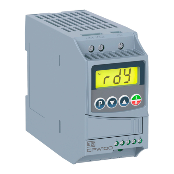
WEG CFW100 series Quick Setup Manual
Mini variable speed drives
Hide thumbs
Also See for CFW100 series:
- Programming manual (159 pages) ,
- User manual (127 pages) ,
- Quick reference (70 pages)
Advertisement
Quick Links
Installation & Power Connections
Refer to user guide chapter 3.
Typical Control Connection
Example 1: 2 - Wire Start/Stop, Speed Potentiometer
OFF
ON
START/STOP
1
DI 1
Digital input 1
OFF
ON
FWD/REV
2
DI 2
Digital input 2
DI 3
Digital input 3
3
DI 4
Digital input 4
4
5
GND
Reference 0 V
6
GND
Reference 0 V
7
AI 1
Analog input 1
+ 10 V dc
Reference + 10 V potentiometer
8
OFF
DIP SWITCH
Speed
Potentiometer
CFW100-IORA
PROG
DEF
User
P0220
0
1
Local/Remote = always remote
P0222
2
1
Remote reference = Al1
P0226
2
4
P0227
3
1
Start/Stop remote = DIx
P0231
0
0
AI1 = speed reference
P0233
0
0
P0263
1
1
P0264
8
8
Programming
Remote Keypad
Run button:
Stop button:
Up/Down buttons:
Prog button:
Motor Overload Settings
PROG
DEF
User
P0156
1.2 x I
1.1 x I
nom
nom
Phone: 800.894.0412 - Fax: 888.723.4773 - Web: www.clrwtr.com - Email: info@clrwtr.com
Example 2: 3 - Wire Start/Stop, 4 - 20 mA Reference
START
STOP
4 - 20 mA
Reference
Description
PROG
P0220
P0222
FWD/REV = DIx
P0227
P0231
P0233
AI1 = 0 - 10 V
P0263
DI1 = start/stop
P0264
DI2 = FWD/REV
Start-Up (Scalar - V/F Mode)
PROG
P0202
P0401
- Run in local mode
P0402
P0403
- Stop in local mode
- Reset
Note: set P0202 = 5 during oriented start-up for improved speed control and
higher torque capacity at low speed (especially <5 Hz).
■
Set as per motor nameplate data.
- Adjust speed in local mode
- Navigate through parameters
Basic Application
- Use to Select/Save
PROG
P0100
P0101
P0133
Description
P0134
Overload current
Note:
Setting depends on application.
▲
1
DI 1
Digital input 1
2
DI 2
Digital input 2
DI 3
3
Digital input 3
DI 4
Digital input 4
4
5
GND
Reference 0 V
6
GND
Reference 0 V
7
AI 1
Analog input 1
+ 10 V dc
Reference + 10 V potentiometer
8
DIP SWITCH
ON
CFW100-IORA
DEF
User
Description
0
1
Local/Remote = always remote
2
1
Remote reference = Al1
3
1
Start/Stop remote = DIx
0
0
AI1 = speed reference
0
1
AI1 = 4 - 20 mA
1
6
DI1 = start
8
7
DI2 = stop
DEF
User
Description
0
0
Control type V/F
-
■
Motor FLC (A)
1710
■
Motor speed (RPM)
■
Motor frequency
60
DEF
User
Description
5s
▲
Acceleration time (s)
▲
10s
Deceleration time (s)
3 Hz
▲
Minimum speed (Hz)
66 Hz
▲
Maximum speed (Hz)
Example 3: 2 - Wire Start/Stop, Multispeed (4 Speeds)
OFF
ON
START/STOP
1
DI 1
Digital input 1
2
DI 2
Digital input 2
OFF
ON
SPEED
3
DI 3
Digital input 3
OFF
ON
SPEED
4
DI 4
Digital input 4
5
GND
Reference 0 V
PROG
DEF
User
P0220
0
1
Local/Remote = always remote
P0222
2
8
Remote reference = multispeed
P0227
3
1
Start/Stop remote = DIx
P0263
1
1
P0265
0
13
P0266
0
13
P0124
3
▲
Speed = ▲ (DI3 = open and DI4 = open)
P0125
10
▲
Speed = ▲ (DI3 = open and DI4 = closed)
▲
Speed = ▲ (DI3 = closed and DI4 = open)
P0126
20
▲
Speed = ▲ (DI3 = closed and DI4 = closed)
P0127
30
Note:
Speed setting depends on application.
▲
Relay Output
9
DO1-RL-C
Common
10
DO1-RL-NO
Normal open
Note: for more advance functions, please refer to the programming manual.
Changing Monitor Display Parameter
User
Description
2
Output speed (Hz)
3
Motor current (A)
5
Output frequency (Hz)
7
Output voltage (V)
9
Motor torque (%)
Direction of rotation
Inverter status
Main display
Bar to monitor the variable. See parameters
207, 208 and 213 to adjust bar graph
Loading Factory Default Setting
PROG
DEF
User
P0204
0
Load factory defaults (60 Hz)
5
Description
DI1 = start/stop
DI3 = multispeed
DI4 = multispeed
PROG
DEF
User Description
11
Run
12
Ready
P0275
13
13
No fault
26
With fault
Unit of measurement
(it refers to the value of
the main display)
Description
Advertisement

Related Manuals for WEG CFW100 series


Summary of Contents for WEG CFW100 series
- Page 1 Installation & Power Connections Refer to user guide chapter 3. Typical Control Connection Example 1: 2 - Wire Start/Stop, Speed Potentiometer Example 2: 3 - Wire Start/Stop, 4 - 20 mA Reference Example 3: 2 - Wire Start/Stop, Multispeed (4 Speeds) START START/STOP START/STOP...
- Page 2 OEM users, such as elevators doors or fitness equipment, as well as small fans, mixing machines, roller tables and special-purpose WEG Electric Corp. machines for small processes. Combining extensive 6655 Sugarloaf Parkway functionality with extremely small size, the CFW100 is...
Need help?
Do you have a question about the CFW100 series and is the answer not in the manual?
Questions and answers