
Related Manuals for Congatec Qseven conga-QA6 015033


Summary of Contents for Congatec Qseven conga-QA6 015033
- Page 1 Qseven conga-QA6 ® Intel Atom™ processor E6xx/E6xxT series with an Intel Platform Controller Hub EG20T ® ® User’s Guide Revision 1.4 Copyright © 2010 congatec AG QTOPm14 1/80...
-
Page 2: Revision History
Suspend Modes and Resume Events” because these options are not supported in the BIOS. • Updated section 9 “BIOS Setup Description”. 2017.02.17 • Corrected WVGA resolution to 800x480. • Updated template and variants. Copyright © 2010 congatec AG QTOPm14 2/80... -
Page 3: Intended Audience
In no event shall congatec AG be liable for any incidental, consequential, special, or exemplary damages, whether based on tort, contract or otherwise, arising out of or in connection with this user’s guide or any other information... -
Page 4: Copyright Notice
Copyright © 2010, congatec AG. All rights reserved. All text, pictures and graphics are protected by copyrights. No copying is permitted without written permission from congatec AG. congatec AG has made every attempt to ensure that the information in this document is accurate yet the information contained within is supplied “as-is”. - Page 5 (c) arising from course of performance, course of dealing, or usage of trade. congatec AG shall in no event be liable to the end user for collateral or consequential damages of any kind. congatec shall not otherwise be liable for loss, damage or expense directly or indirectly arising from the use of the product or from any other cause.
-
Page 6: Technical Support
Technical Support congatec AG technicians and engineers are committed to providing the best possible technical support for our customers so that our products can be easily used and implemented. We request that you first visit our website at www.congatec.com for the latest documentation, utilities and drivers, which have been made available to assist you. -
Page 7: Table Of Contents
Fan Control ................30 Feature List ................13 Additional Features ..............31 Supported Operating Systems ..........14 congatec Board Controller (cGB) ..........31 Mechanical Dimensions ............14 Board Information ..............31 Supply Voltage Standard Power ..........15 Watchdog ................31 2.4.1... - Page 8 Save & Exit ................78 10.8.1 Save & Exit Menu ..............78 Additional BIOS Features ............79 11.1 Updating the BIOS ..............79 11.2 BIOS Security Features ............79 Industry Specifications ............. 80 Copyright © 2010 congatec AG QTOPm14 8/80...
- Page 9 Table 33 Bootstrap Signal Descriptions ..........57 Table 34 IRQ Lines in PIC mode ............. 58 Table 35 IRQ Lines in APIC mode ............59 Table 36 PCI Configuration Space Map ..........60 Copyright © 2010 congatec AG QTOPm14 9/80...
-
Page 10: Introduction
Simply unplug one module and replace it with another, no need to redesign the carrier board. This document describes the features available on the Qseven evaluation carrier board. Additionally, the schematics for the Qseven evaluation ® ® carrier board can be found on the congatec website. Copyright © 2010 congatec AG QTOPm14 10/80... -
Page 11: Table 1 Conga-Qa6 Commercial Variants
The conga-QA6 is currently available in several different variants. This user’s guide describes the available features these different variants offer. Below you will find an order table showing the base configuration modules that are currently offered by congatec AG. For more information about the additional conga-QA6 variants offered by congatec, contact your local congatec sales representative or visit the congatec website at www.congatec.com. - Page 12 ® L2 Cache 512kB 512kB Onboard Memory 2GB DDR2 (800 MT/s) 1GB DDR2 (667 MT/s) External PCI Express Lane(s) Gigabit Ethernet Onboard Solid-State Drive (SSD) CAN Bus CPU TDP 4.5 W 2.7 W Copyright © 2010 congatec AG QTOPm14 12/80...
-
Page 13: Specifications
Optionally equipped with a Solid State Drive (SSD) up to 32 GByte in capacity BIOS AMI Aptio UEFI 2.x firmware, 4MByte serial SPI with congatec Embedded BIOS features ® Power Mgmt. ACPI 3.0 compliant with battery support. Also supports Suspend to RAM (S3). -
Page 14: Supported Operating Systems
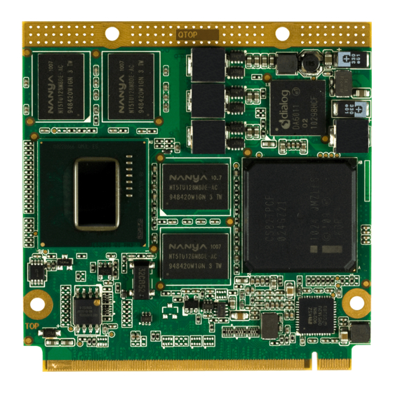
Dimension is dependent on connector height used Dimension is dependent 1.20 ±0.1 on connector height used All measurements are in millimeters All dimensions without tolerance ±0.2mm Carrier Board PCB Rear View of Qseven Module Copyright © 2010 congatec AG QTOPm14 14/80... -
Page 15: Supply Voltage Standard Power
The input voltages shall rise from 10% of nominal to 90% of nominal at a minimum slope of 250V/s. The smooth turn-on requires that during the 10% to 90% portion of the rise time, the slope of the turn-on waveform must be positive. Copyright © 2010 congatec AG QTOPm14... -
Page 16: Power Consumption
Power Consumption The power consumption values were measured with the following setup: • conga-QA6 • modified congatec carrier board • conga-QA6 cooling solution • Microsoft Windows 7 (32 bit) Note The CPU was stressed to its maximum workload with the Intel Thermal Analysis Tool ®... -
Page 17: Supply Voltage Battery Power
RTC battery within a system featuring this chipset will be depleted after as little as 8 months. congatec solves this RTC current leakage problem by using the onboard board controller found on the conga-QA6. When the conga-QA6 is powered off, the EG20T RTC is disconnected and the onboard board controller’s RTC is used. When the conga-QA6 is restarted, the BIOS overwrites the EG20T system clock with the correct one provided by the congatec board controller. -
Page 18: Environmental Specifications
4. We recommend to always have a CMOS battery present when operating the conga-MA5. Environmental Specifications The above operating temperatures must be strictly adhered to at all times. When using a congatec heatspreader, the maximum operating temperature refers to any measurable spot on the heatspreader’s surface. Humidity specifications are for non-condensing conditions. -
Page 19: Block Diagram
Intel® Atom™ Board Controller STM32F100R8T6b processor E6xx/E6xxT Series Hardware Monitoring BIOS Fan Control Circuitry (Flash) Intel® Platform Controller Hub EG20T Micrel® Gbit Ethernet Phy KSZ9021RN(I) SSD NandDrive (optional) SATA1 Uses SATA 1 Control Copyright © 2010 congatec AG QTOPm14 19/80... -
Page 20: Cooling Solutions
(-40° to 85°C), use of the conga-QA6 heatspreaders is not recommended by congatec and furthermore its use is at the risk of the end user. It is the responsibility of the end user to design an optimized thermal solution that meets the needs of their application within the industrial environmental conditions it is required to operate in. -
Page 21: Heatspreader And Aluminum Standoff Dimensions
Qseven Design Guide. Caution When using the heatspreader in a high shock and/or vibration environment, congatec recommends the use of a thread-locking fluid on the heatspreader screws to ensure the above mentioned torque specification is maintained. -
Page 22: Heatspreader And Aluminum Standoff Exploded View
Heatspreader and Aluminum Standoff Exploded View Note Torque specification for heatspreader screws is 0.3 Nm. Heatspreader utilizes micro pins to ensure that the thermal stacks always remain in place. Copyright © 2010 congatec AG QTOPm14 22/80... -
Page 23: Connector Subsystems
3 PCI Express Lanes 1x SDVO 2x Serial ATA I²C Bus 400 kHz 8x USB 2.0 SPI Bus HDA/Digital Audio I/F LVDS Gigabit Ethernet Watchdog CAN Bus Power Control LPC Bus Power Management Fan Control Copyright © 2010 congatec AG QTOPm14 23/80... -
Page 24: Pci Express
Note For conga-QA6 rev C.x and earlier, congatec AG reccommends not to connect the center-taps of the magnetics to either each other or to CTREF pin. Serial ATA™ (SATA) -
Page 25: Usb 2.0
Display Pipe A. It supports the connection of 1x18 or 1x24 bit data mapping up to a resolution of 1280x768@60Hz. For more information about the supported resolutions, see table 2 below. Copyright © 2010 congatec AG QTOPm14... -
Page 26: Sdvo
60 Hz 138.5 MHz 1280x1024 75 Hz 138.75 MHz 1920x1080 50 Hz 141.5 MHz 1280x960 85 Hz 148.25 MHz 1400x1050 75 Hz 156 MHz 1280x1024 85 Hz 159.5 MHz Max SDVO interface support Copyright © 2010 congatec AG QTOPm14 26/80... -
Page 27: Displayport
A SPI interface that supports booting from an external SPI flash is available on the conga-QA6. This interface is provided by the Intel ® Atom™ processor E6xx/E6xxT series and only supports the connection of an external SPI flash to enable external boot capabilities. Copyright © 2010 congatec AG QTOPm14 27/80... -
Page 28: Can Bus
When PWRBTN# is asserted it indicates that an operator wants to turn the power on or off. The response to this signal from the system may vary as a result of modifications made in BIOS settings or by system software. Copyright © 2010 congatec AG QTOPm14... -
Page 29: Power Management
ACPI 3.0 compliant with battery support. Also supports Suspend to RAM (S3). No support for legacy APM. 5.17 I²C Bus The I²C bus is implemented through the use of STMicroelectronics STM32F100R8 microcontroller. It provides a multi-master I²C Bus that has maximum I²C bandwidth. Copyright © 2010 congatec AG QTOPm14 29/80... -
Page 30: Watchdog
The conga-QA6 is equipped with a multi stage watchdog solution that can be triggered by software or external hardware. For more information about the Watchdog feature see the BIOS setup description of this document and application note AN3_Watchdog.pdf on the congatec AG website at www.congatec.com. -
Page 31: Additional Features
The conga-QA6 is equipped with an STMicroelectronics STM32F100R8 microcontroller. This onboard microcontroller plays an important role for most of the congatec BIOS features. It fully isolates some of the embedded features such as system monitoring or the I²C bus from the x86 core architecture, which results in higher embedded feature performance and more reliability, even when the x86 processor is in a low power mode. -
Page 32: Embedded Bios
OEM BIOS Code With the congatec embedded BIOS it is even possible for system designers to add their own code to the BIOS POST process. Except for custom specific code, this feature can also be used to support Win XP SLP installation, Window 7 SLIC table, verb tables for HDA codecs, rare graphic modes and Super I/O controllers. -
Page 33: Api Support (Cgos/Eapi)
EAPI (Embedded Application Programming Interface) is a programming interface defined by the PICMG that addresses this problem. With this unified API it is now possible to run the same application on all vendor’s COMs that offer EAPI driver support. Contact congatec technical support for more information about EAPI. - Page 34 EWF mechanism is used thereby limiting the write-cycles in order to maintain sufficient free disk space. Failure to use a EWF mechanism will void the warranty of the SSD drive. Note For more information about the SSD drive’s capability refer to the manufacturers datasheet. Copyright © 2010 congatec AG QTOPm14 34/80...
-
Page 35: Conga Tech Notes
To ensure that the TCC is active for only short periods of time thus reducing the impact on processor performance to a minimum, it is necessary to have a properly designed thermal solution. The Intel® Atom™ processor E6xx/E6xxT series respective datasheet can provide more information about this subject. Copyright © 2010 congatec AG QTOPm14 35/80... -
Page 36: Processor Performance Control
You can find more information about Intel Virtualization Technology at: http://developer.intel.com/technology/virtualization/index.htm Note congatec does not offer virtual machine monitor (VMM) software. All VMM software support questions and queries should be directed to the VMM software vendor and not congatec technical support. -
Page 37: Thermal Management
If passive cooling is activated and the processor temperature is above the trip point, the processor clock is throttled according to the formula below. ∆P[%] = TC1(T ) + TC2(T • ∆P is the performance delta Copyright © 2010 congatec AG QTOPm14 37/80... -
Page 38: Acpi Suspend Modes And Resume Events
Device driver must be configured for Wake On LAN support. Featured must be enabled in BIOS setup. PCI Express WAKE# Wakes unconditionally from S3. Watchdog Power Button Event Wakes unconditionally from S3 and S5. Note The above list has been verified using a Windows XP SP3 ACPI enabled installation. Copyright © 2010 congatec AG QTOPm14 38/80... -
Page 39: Usb Port Connections
USB Port Connections The 6 USB ports are shared between 2 EHCI host controllers. Ports 0-5 are capable of supporting USB 1.1 and 2.0 compliant devices. congatec has implemented a USB 2.0 hub on the conga-QA6 that provides two additional ports for a total of 8. See conga-QA6 USB Routing Diagram on the following page. -
Page 40: Important Information
There are certain limitations associated with the Intel platform featured on the conga-QA6 as well as the module itself. These limitation are documented in a conga-QA6 Fact Sheet. For information about the conga-QA6 Fact Sheet contact your local congatec representative. -
Page 41: Signal Descriptions And Pinout Tables
The “#” symbol at the end of the signal name indicates that the active or asserted state occurs when the signal is at a low voltage level. -
Page 42: Table 11 Edge Finger Pinout
HD Audio/AC’97 Serial Data Out I2C_DAT I2C Bus Data THRM# Thermal Alarm active low WDTRIG# Watchdog trigger signal THRMTRIP# Thermal Trip indicates an overheating condition WDOUT Watchdog event indicator Power Ground Power Ground Copyright © 2010 congatec AG QTOPm14 42/80... - Page 43 SDVO Blue line+ 144 SDVO_TVCLKIN+ SDVO TV-Out line+ SDVO_BLUE- SDVO Blue line- 146 SDVO_TVCLKIN- SDVO TV-Out line- Power Ground 148 GND Power Ground SDVO_RED+ SDVO Red line+ 150 SDVO_CTRL_DAT I2C based control clock for SDVO Copyright © 2010 congatec AG QTOPm14 43/80...
- Page 44 Power supply +5VDC ±5% Power supply +5VDC ±5% 222 VCC Power supply +5VDC ±5% Power supply +5VDC ±5% 224 VCC Power supply +5VDC ±5% Power supply +5VDC ±5% 226 VCC Power supply +5VDC ±5% Copyright © 2010 congatec AG QTOPm14 44/80...
-
Page 45: Table 12 Pci Express Signal Descriptions
PU 10k 3.3V EXCD0_PERST# ExpressCard slot #0 reset. O 3.3V PU 10k 3.3V EXCD1_CPPE# ExpressCard slot #1 capable card request. I 3.3V Not supported EXCD1_PERST# ExpressCard slot #1 reset. O 3.3V Not supported Copyright © 2010 congatec AG QTOPm14 45/80... -
Page 46: Table 14 Ethernet Signal Descriptions
(see note below) Note Some signals have special functionality during the reset process. They may bootstrap some basic important functions of the module. For more information refer to section 8.1 of this user’s guide. Copyright © 2010 congatec AG QTOPm14 46/80... -
Page 47: Table 15 Sata Signal Descriptions
USB Ports 0 and 1. 3.3VSB USB_2_3_OC# Over current detect input 2. This pin is used to monitor the USB power I 3.3VSB PU 10k over current of the USB Ports 2 and 3. 3.3VSB Copyright © 2010 congatec AG QTOPm14 47/80... -
Page 48: Table 17 Sdio Signal Descriptions
SDIO Power Enable. This signal is used to enable the power being supplied to a SD/ O 3.3V PU 10k MMC card device. 3.3V SDIO_DAT0 SDIO Data lines. These signals operate in push-pull mode. I/O 3.3V PU 10k SDIO_DAT1 3.3V SDIO_DAT2 SDIO_DAT3 SDIO_DAT4 SDIO_DAT5 SDIO_DAT6 SDIO_DAT7 Copyright © 2010 congatec AG QTOPm14 48/80... -
Page 49: Table 18 Hda/Ac'97 Signal Descriptions
LVDS secondary channel differential pair 2. O LVDS Not supported LVDS_B2- LVDS_B3+ LVDS secondary channel differential pair 3. O LVDS Not supported LVDS_B3- LVDS_B_CLK+ LVDS secondary channel differential pair clock lines. O LVDS Not supported LVDS_B_CLK- Copyright © 2010 congatec AG QTOPm14 49/80... -
Page 50: Table 20 Sdvo Signal Descriptions
Note The SDVO interface signals are shared with the signals for the DisplayPort interface and/or the TMDS interface. The conga-QA6 does not support the DisplayPort/TMDS interface. Copyright © 2010 congatec AG QTOPm14 50/80... -
Page 51: Table 21 Displayport Signal Descriptions
Hot plug detection signal that serves as an interrupt request. I 3.3V HDMI interface not supported Note The TMDS interface signals are shared with the signals for the SDVO interface and/or the DisplayPort interface. HDMI interface is not supported on the conga-QA6. Copyright © 2010 congatec AG QTOPm14 51/80... -
Page 52: Table 23 Lpc Signal Descriptions
RX input for CAN Bus channel 0. In order to connect a CAN controller device to I 3.3V PU 10k the Qseven module’s CAN bus it is necessary to add transceiver hardware to the 3.3V ® carrier board. Copyright © 2010 congatec AG QTOPm14 52/80... -
Page 53: Table 26 Power And Gnd Signal Descriptions
LID button. Low active signal used by the ACPI operating system to detect a LID switch I 3.3VSB PU 10k and to bring system into sleep state or to wake it up again. 3.3VSB Copyright © 2010 congatec AG QTOPm14 53/80... -
Page 54: Table 29 Miscellaneous Signal Descriptions
I 3.3V PU 10k 3.3V /BOOT_ALT# Allows off-module BIOS implementations. This signal can also be used to disable standard boot firmware flash device and enable an alternative boot firmware source, for example a bootloader. Copyright © 2010 congatec AG QTOPm14 54/80... -
Page 55: Table 30 Manufacturing Signal Descriptions
For this reason, a level shifting device may be required on the carrier board to guarantee that these voltage levels are correct in order to prevent damage to the module. More information about implementing a carrier board multiplexer can be found in the Qseven ® Design Guide. Copyright © 2010 congatec AG QTOPm14 55/80... -
Page 56: Table 31 Thermal Management Signal Descriptions
General Purpose PWM Output. FAN_TACHOIN Primary functionality is fan tachometer input. When not in use for this primary purpose it can I 3.3V /GP_TIMER_IN be used as General Purpose Timer Input. Copyright © 2010 congatec AG QTOPm14 56/80... -
Page 57: Bootstrap Signals
Additionally, if it is necessary to have link and activity LEDs connected to GBE_LINK# and GBE_ACT# on the carrier board, then buffers must be used since without a buffer the strapping becomes active and the PHY will be programmed to a wrong address. Copyright © 2010 congatec AG QTOPm14... -
Page 58: System Resources
In PIC mode, the PCI bus interrupt lines can be routed to any free IRQ. Note In ACPI mode, IRQ9 is used for the SCI (System Control Interrupt). The SCI can be shared with a PCIe interrupt line. Copyright © 2010 congatec AG QTOPm14 58/80... -
Page 59: Table 35 Irq Lines In Apic Mode
PCIe Bridge 0, PCIe Port 1 Slot, PCIe Port 2 Slot, PCIe Port 3 Slot PCIe Bridge 0, PCIe Port 1 Slot, PCIe Port 2 Slot, PCIe Port 3 Slot PCIe Bridge 0, PCIe Port 1 Slot, PCIe Port 2 Slot, PCIe Port 3 Slot Copyright © 2010 congatec AG QTOPm14 59/80... -
Page 60: Pci Configuration Space
USB 2.0 OHCI Host 2 Internal USB 2.0 OHCI Host 2 Internal Shared DMA Internal UART 0 Internal UART 1 Internal UART 2 Internal UART 3 Internal Shared DMA Internal Internal Internal Internal IEEE1588 Copyright © 2010 congatec AG QTOPm14 60/80... -
Page 61: Pci Interrupt Routing
Interrupt used by single function PCI Express devices (INTA). Interrupt used by multifunction PCI Express devices (INTB). Interrupt used by multifunction PCI Express devices (INTC). Interrupt used by multifunction PCI Express devices (INTD). Copyright © 2010 congatec AG QTOPm14 61/80... -
Page 62: Bios Setup Description
POST thereby allowing the operator to choose the boot device to be used. 10.2 Setup Menu and Navigation The congatec BIOS setup screen is composed of the menu bar and two main frames. The menu bar is shown below: Main Advanced... -
Page 63: Main Setup Screen
Displays the hardware revision of the board. Serial Number no option Displays the serial number of the board. BC Firmware Rev. no option Displays the revision of the congatec board controller. Boot Counter no option Displays the number of boot-ups. (max. 16777215). MAC Address no option Displays the MAC address of the board. -
Page 64: Platform Information Submenu
Main Advanced Boot Security Power Exit Graphic Configuration Watchdog Configuration PCI Subsystem Settings ACPI Configuration CPU Configuration Chipset Configuration AHCI SATA Configuration SDIO Configuration USB Configuration Super IO Configuration Serial Port Console Redirection Copyright © 2010 congatec AG QTOPm14 64/80... -
Page 65: Graphics Configuration Submenu
640x480 1x18 (013h) Auto detection is performed by reading an EDID data set via the video I²C bus. The number in brackets specifies the congatec internal number of the respective panel data set. WVGA 800x480 1x24 (01Bh) SVGA 800x600 1x18 (01Ah) Note: Customized EDID™... -
Page 66: Watchdog Configuration Submenu
Selects the type of event that will be generated when timeout 2 is reached. Disabled ACPI Event Reset Power Button Event 3 Selects the type of event that will be generated when timeout 3 is reached. Disabled ACPI Event Reset Power Button Copyright © 2010 congatec AG QTOPm14 66/80... -
Page 67: Pci Subsystem Settings Submenu
Enables or Disables PCI device to generate SERR#. Disabled Enabled Relaxed Ordering Enables or Disables PCI Express device Relaxed Ordering. Disabled Enabled Reserved Interrupt 1 Reserves additional IRQ for custom purposes. None IRQ3 IRQ4 IRQ6 IRQ7 IRQ10 IRQ11 IRQ14 IRQ15 Copyright © 2010 congatec AG QTOPm14 67/80... -
Page 68: Pci Express Ports 1-4 Configuration Submenu
Sets Interrupt for selected PIRQ. Refer to the board’s Resource List for a detailed description of devices Auto IRQ3 connected to the respective PIRQ. IRQ4 IRQ6 This setup node is only effective while operating in PIC (non IOAPIC) interrupt mode. IRQ7 IRQ10 IRQ11 IRQ14 IRQ15 Copyright © 2010 congatec AG QTOPm14 68/80... -
Page 69: Pci To Pci Bridge Submenu
100°C Note In ACPI mode it is not possible for a “Watchdog ACPI Event” handler to directly restart or shutdown the OS. For this reason the congatec BIOS will do one of the following: For Shutdown: An over temperature notification is executed. This causes the OS to shut down in an orderly fashion. - Page 70 If this option is not selected then Windows will remain at a blue-screen after a ‘Watchdog ACPI Event” that has been configured for ‘Restart’ has been generated. Below is a Windows screen-shot showing the proper configuration. Win XP/2000 Watchdog ACPI Event restart configuration Copyright © 2010 congatec AG QTOPm14 70/80...
-
Page 71: Cpu Configuration Submenu
Enhanced C-2 Enables or disables the Enhanced C2 State. Disabled Enabled Enhanced C-3 Enables or disables the Enhanced C3 State. Disabled Enabled Enhanced C-4 Enables or disables the Enhanced C4 State. Disabled Enabled Copyright © 2010 congatec AG QTOPm14 71/80... -
Page 72: Chipset Configuration Submenu
WOL Mode Selects WOL Mode. Wake Up Frame Magic packet Hidden if Wake on LAN is disabled. WOL Speed Selects WOL Speed. 10 Mbps 100Mbps Hidden if Wake on LAN is disabled. 1000Mbps Copyright © 2010 congatec AG QTOPm14 72/80... -
Page 73: Ahci Sata Configuration
Works only for drives formatted with FAT12, FAT16 or FAT32. Hard Disk allows the device to be emulated as hard disk. CDROM assumes the CD-ROM is formatted as bootable media, specified by the ‘El Torito’ Format Specification. Copyright © 2010 congatec AG QTOPm14 73/80... -
Page 74: Super I/O Configuration Submenu
Selects the IO port address and Interrupt for the SIO Port [IO=3F8; IRQ=4] [IO=3F8 IRQ=3,4,5,6,7, 8, 9,10,11,12] [IO=2F8 IRQ=3,4,5,6,7, 8, 9,10,11,12] [IO=3E8 IRQ=3,4,5,6,7, 8, 9,10,11,12] [IO=2E8 IRQ=3,4,5,6,7, 8, 9,10,11,12] Device Mode Changes the serial port mode Normal High Speed Copyright © 2010 congatec AG QTOPm14 74/80... -
Page 75: Serial Port Console Redirection
Disabled Enabled Out-of-Band Mgmt Port Defines the Serial Pot used for the Windows EMS COM0 COM1 COM4 Terminal Type VT100 This note defines the Terminal Type used for the connection. VT100+ VT-UTF8 ANSI Copyright © 2010 congatec AG QTOPm14 75/80... -
Page 76: 10.5.14.1 Console Redirection Settings
Enables or disables extended terminal resolution. Disabled Enabled Legacy OS Redirection Legacy OS Redirection Resolution. 80x24 Resolution 80x25 10.6 etup Select the Boot tab from the setup menu to enter the Boot setup screen. Copyright © 2010 congatec AG QTOPm14 76/80... -
Page 77: Boot Settings Configuration Submenu
Always Upon Request = Gate A20 can be disabled using BIOS services. Always = Do not allow disabling Gate A20. Option ROM Force BIOS Set display mode for option ROMs. Messages Keep Current Copyright © 2010 congatec AG QTOPm14 77/80... -
Page 78: Security Setup
Save changes made so far to any of the setup options. Stay in setup menu. Discard Changes Discard changes made so far to any of the setup options. Stay in setup menu. Restore Defaults Restore default values for all the setup options. Copyright © 2010 congatec AG QTOPm14 78/80... -
Page 79: Additional Bios Features
Additional BIOS Features The conga-QA6 uses a congatec/AMI AptioEFI that is stored in an onboard SPI Flash chip and can be updated using the congatec System Utility, which is available in a DOS based command line, Win32 command line, Win32 GUI, and Linux version. -
Page 80: Industry Specifications
Industry Specifications The list below provides links to industry specifications that apply to congatec AG modules. Table 38 Industry Specifications Specification Link Qseven ® Specification http://www.qseven-standard.org/ Qseven Design Guide http://www.qseven-standard.org/ ® Low Pin Count Interface Specification, Revision 1.0 (LPC) http://developer.intel.com/design/chipsets/industry/lpc.htm Universal Serial Bus (USB) Specification, Revision 2.0...
Need help?
Do you have a question about the Qseven conga-QA6 015033 and is the answer not in the manual?
Questions and answers