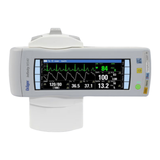
Dräger Infinity M540 Instructions For Use Manual
Acute care system patient monitor with vg2 software
Hide thumbs
Also See for Infinity M540:
- Instructions for use manual (610 pages) ,
- Quick reference manual (24 pages) ,
- Instructions for use manual (350 pages)

Related Manuals for Dräger Infinity M540


Summary of Contents for Dräger Infinity M540
- Page 1 Instructions for Use Infinity Acute Care System M540 Patient Monitor WARNING To properly use this medical device, Software VG2 read and comply with these Instruc- tions for Use.
-
Page 2: Patient Preparation For Spo
Typographical conventions Any text shown on the screen and any labeling on 1 Consecutive numbers indicate steps of action, the device are printed in bold and italics, for exam- with the numbering restarting with "1" for each ple, Alarms, or Menu. new sequence of actions. - Page 3 Trademarks and patents – Acute Care System – Durasensor ® ® – DrägerService – Nellcor ® ® – Infinity – OxiMax ® – Hemo4 – OxiCliq ® – Hemo2 – OxiBand ® – Innovian – SoftCare ® ® – MCable –...
- Page 4 Safety information definitions WARNING CAUTION A WARNING statement provides important A CAUTION statement provides important infor- information about a potentially hazardous mation about a potentially hazardous situation situation which, if not avoided, could result in which, if not avoided, may result in minor or mod- death or serious injury.
-
Page 5: Table Of Contents
Alarm priorities ......62 Infinity M540 ......18 Alarm processing. - Page 6 Contents Selecting ARR leads ....106 and pulse rate with Nellcor OxiMax ARR modes ......107 MCable .
- Page 7 Viewing the system information ... . 205 Infinity M540 ......252 Configuring the biomed settings .
- Page 8 This page intentionally left blank Instructions for Use Infinity Acute Care System – M540 Patient Monitor SW VG2...
- Page 9 For your safety and that of your patients For your safety and that of your patients Strictly follow these Instructions for Use ..10 Training....... 10 Safety inspections and maintenance .
-
Page 10: Strictly Follow These Instructions For Use
For your safety and that of your patients Strictly follow these Instructions for Use Safety inspections and maintenance WARNING WARNING Every medical device must be inspected regu- Any use of the medical device requires full larly to ensure it remains safe to use. understanding and strict observation of all sections of these Instructions for Use. -
Page 11: Accessories
For your safety and that of your patients Accessories Connected devices WARNING WARNING Only the accessories indicated in the Infinity Connecting devices or combinations of Acute Care System – M540 Patient Monitor devices in ways not described within these Instructions for Use (latest edition) have been Instructions for Use may adversely affect the tested and approved for use with the medical operation of any or all of the connected medi-... -
Page 12: Connection To Hospital Network
For your safety and that of your patients Patient safety – IEC 60601-1-4 (EN 60601-1-4) Medical electrical equipment Part 1-4: General requirements for safety The design of the medical device, the accompany- Collateral standard: Programmable electrical ing documentation, and the labeling on the medical medical systems device are based on the assumption that the pur- chase and the use of the medical device are... -
Page 13: For Your Safety And That Of Your Patients
For your safety and that of your patients General safety information Restriction of Distribution The following WARNING and CAUTION state- ments apply to general operation of the medical device. Federal Law (U.S.) restricts this device to sale by or WARNING and CAUTION statements specific to on the order of a physician. -
Page 14: Information On Electromagnetic Compatibility
For your safety and that of your patients Information on electromagnetic CAUTION compatibility To prevent overheating, do not place the device in direct sunlight or near radiant heaters. Medical electrical equipment is subject to special precautionary measures concerning electromag- CAUTION netic compatibility (EMC) and must be installed and After extended exposure in a cold environment, put into operation in accordance with the EMC... -
Page 15: Electrosurgery
For your safety and that of your patients CAUTION WARNING Using ECG electrodes and cables specified by To reduce the hazard of burns during electro- Dräger protects the device from damage during surgery, keep the sensor or transducer (ECG, defibrillation and reduces noise and other interfer- pressure, SpO ) and their associated cables ence on the ECG waveform. - Page 16 This page intentionally left blank Instructions for Use Infinity Acute Care System – M540 Patient Monitor SW VG2...
-
Page 17: Intended Use
Intended use Infinity M540 ......18 Indications for use ..... . 18... -
Page 18: Infinity M540
Intended use Infinity M540 The Infinity M540 (M540) is intended for the moni- The M540 and any connected hardware are not toring of multi-parameter, physiologic patient infor- intended for use in the following hospital environ- mation obtained from connected hardware in... -
Page 19: System Overview
System overview Overview of Infinity M540 ....20 M540 front panel......21 M540 back panel . -
Page 20: Overview Of Infinity M540
B M500 which is the display module of the Infinity Acute Care System C System cable (MS20345) – M540 – refers to the Infinity M540 patient mon- D PS50 power supply itor E PS50 power cable – M500 – refers to the Infinity M500 that secures... -
Page 21: M540 Front Panel
System overview M540 front panel M540 fixed keys The M540 has the following fixed keys: The following illustration shows the elements of the front panel. Function On/off fixed key Turns the M540 on or off. The button LED flashes when the M540 is undocked;... -
Page 22: M540 Back Panel
System overview M540 back panel M540 side panel A NIBP A Charging contact points B Temp (2) / Aux B Labels C SpO C Optical Ethernet links D Hemo E CO F ECG Instructions for Use Infinity Acute Care System – M540 Patient Monitor SW VG2... -
Page 23: Infinity M500 Docking Station
System overview Infinity M500 docking station M500 back panel The M500 is the mechanical device that secures and powers the M540. The M500 also charges the battery of the M540. If the M540 is part of an IACS configuration, the M500 controls the communica- tion between the M540 and the Cockpit through an optical Ethernet link. -
Page 24: Additional Hardware
System overview M540 docked in the M500 The following diagram shows the M540 docked in the M500. A M540 B M500 Additional hardware The following table lists the additional devices that can be connected to the M540. Device Description Connection Infinity MCable –... - Page 25 System overview Hemo4 pod Measures up to four pressures, Connects directly to the Hemo cardiac output, core and body connector of the M540 (see infor- Infinity MPod – QuadHemo surface temperature. mation starting on see page 173). Hemo2 pod Measures up to two pressures, cardiac output, core and body surface temperature.
-
Page 26: Device Symbols
System overview Device symbols Read accompanying documents for spe- Alarm monitoring deactivated temporarily cific safety information Attention: consult accompanying docu- Alarm monitoring deactivated permanently ments Battery status (when the battery is fully Acoustic alarm signal tone paused tempo- charged, all segments in the symbol are rarily filled in) Function/setting is unlocked... -
Page 27: Wireless Symbols
System overview Battery charging LED Adult patient category The speaker is deactivated Pediatric patient category ESD warning Neonatal patient category The M540 is docked and connected to the network Wireless symbols The following symbols appear in the header bar of the M540 only when it is on wireless transport. -
Page 28: Abbreviations
System overview Abbreviations The following table lists the abbreviations in these Abbrevia- Description Instructions for Use and those abbreviations that tion are displayed on the M540. central venous pressure Abbrevia- Description dV1 to dV6 derived chest leads tion electrocardiogram %paced percentage of paced beats end-tidal (in combination with gas asystole... - Page 29 System overview Abbrevia- Description Abbrevia- Description tion tion NIBP M NIBP mean value STd(x) ST deviation of derived leads (dV1 to dV6) NIBP S NIBP systolic value supraventricular tachycardia pulmonary arterial pressure TACH tachycardia PA D PA diastolic value Tblood blood temperature PA M PA mean value...
- Page 30 This page intentionally left blank Instructions for Use Infinity Acute Care System – M540 Patient Monitor SW VG2...
-
Page 31: Operating Concept
Operating concept Operating concept Overview ......32 M540 wireless mode....32 Communicating with the Infinity network . -
Page 32: Overview
Operating concept Overview The M540 is a portable patient monitor that accom- figuration, refer to the Instructions for Use entitled panies the patient from the bedside to anywhere in ’Infinity Acute Care System – Monitoring Applica- the hospital. This small, lightweight, splash-resis- tions’. -
Page 33: Communicating With The Infinity Network
Operating concept Communicating with the Infinity network Configuration changes while on wireless transport An M540 with the wireless option activated is Infin- Any changes (including changes from the ICS) that ity OneNet compatible. were made to the patient profile (for example, alarm limits) while the M540 was on wireless transport are The following data are made available to the Infinity reset to the profile settings of the Cockpit once the... -
Page 34: Network Communication Interruptions
Operating concept – No waveform and no parameter box are The ICS also displays trend data for an M540 on repeated more than once. Therefore, the next wireless transport. The trend graph and trend table unique waveform becomes channel 2 on the screens on the ICS only display parameters that ICS BedView. -
Page 35: Remote Control
Operating concept Remote control You can view the data of an M540 on wireless You can perform the following functions remotely transport remotely from one of the following from the listed devices for a wireless M540 on devices: transport (refer to the Instructions for Use of the device for details on performing the remote func- –... -
Page 36: Recordings For M540 On Wireless Transport
Operating concept Configuring alarm limits Auto setting alarm limits Configuring arrhythmia settings Configuring ST settings Reviewing trend data Initiate relearning Change the demographic data of the patient Recordings for M540 on wireless transport When the M540 is on wireless transport, pressing the Record function key stores a recording in the M540 which is transferred to the Cockpit once the M540 is docked in an IACS configuration. -
Page 37: Function Keys
Operating concept Function keys A total of eight function keys are located on the front Function Function panel of the M540 (4 on the right and 4 on the left side). Menu Opens the Main dialog win- (fixed) dow. It also closes any open The function keys in positions 2, 3, 4 and 7 are per- dialog and returns you to the manently assigned to the functions Review, Menu... -
Page 38: Monitoring Area
Operating concept Alternate function key assignments To program a function key 1 Touch the Menu function key. Function 2 Touch the Screen setup tab > Function keys tab. Privacy Places the M540 into privacy mode (see page 46). This mode is 3 Touch one of the programmable setup keys only available when the patient is (Setup key 1, Setup key 2, Setup key 3, or... -
Page 39: Parameter Boxes
Operating concept Parameter boxes Each parameter box contains real-time values of a When a parameter is in alarm, the parameter box parameter and a combination of the following infor- flashes in the color of the alarm grade mation: (see page 65) and a corresponding alarm message appears in the header bar. -
Page 40: Dialog Windows
Operating concept Dialog windows The following diagram shows how the monitoring To access dialog windows touch the function keys area appears when accessing a dialog window. on the front of the M540. To access parameter-spe- The left side is reserved for the dialog window while cific setup pages directly, touch the corresponding the right side displays the parameter boxes. -
Page 41: Adjusting The Display
Operating concept Adjusting the display If the orientation of the device changes during To flip the screen manually patient transport, the Auto flip function allows the 1 Touch the Menu function key. screen to flip by 180°. This feature can be turned on or off. -
Page 42: Battery Power
Operating concept Battery power Battery operating times The M540 automatically switches to battery power when it is undocked or if there is a loss of power to the M500. The following table lists the operating times of a fully charged internal battery powers an M540 that When the M540 is docked, the M500 continuously is monitoring ECG, SpO , and Temp continuously,... -
Page 43: Power-Saving Mode
Operating concept Power-saving mode When the M540 is not docked, the power save To activate/deactivate power save mode mode conserves battery power while continuing to 1 Touch the Menu function key. monitor a patient. 2 Touch the Screen setup tab > Settings tab. When power save mode is activated, the display of the M540 is turned off. -
Page 44: Profiles
Operating concept To select a view To assign a pre-configured view to a view key Touch the currently selected function key sev- 1 Touch the Menu function key. eral times (for example, View 5) to scroll 2 Touch the Screen setup tab > Screen views through the available view labels. -
Page 45: Standby Mode
Operating concept Standby mode You can temporarily interrupt patient monitoring by To place the M540 in standby mode placing the M540 in standby mode. Press the Standby function key (if available for Standby mode has the following effect: display, see page 37). –... -
Page 46: Privacy Mode
Operating concept Privacy mode Privacy mode is available when the M540 is docked To place the M540 into privacy mode in an IACS configuration or if it is on wireless trans- Press the Privacy function key (if available for port provided the patient is admitted at the Infinity display, see page 37). -
Page 47: Assembly
Assembly Assembly Overview ......48 Commercially available M500 mounting solutions ......48 Docking/undocking the M540 . -
Page 48: Overview
Assembly Overview Commercially available M500 mounting This section describes the following basic assem- bly tasks: solutions – Docking/undocking the M540 from the M500 Various mounting solutions are available. It is the – Locking/unlocking the M540 into the M500 responsibility of the hospital to install, test, and ensure the proper and safe operation of any mount- –... -
Page 49: Docking/Undocking The M540
Assembly Docking/undocking the M540 The following diagram shows the side and front To dock the M540 panel of the M500 which holds the M540 in place. 1 Align the curved portion of the M540 with the curved portion of the M500. Front view 2 Press the M540 (B) into the M500 (C) until it ‘clicks’... -
Page 50: Locking/Unlocking The M540
Assembly Locking/unlocking the M540 You can lock the M540 permanently in the M500 to To unlock the M540 prevent anyone from undocking it. 1 Insert the 2 mm Allen key (A) into the middle hole (B) on the locking tab and turn it counter- To lock the M540 clockwise to the unlocked position 1 Push the locking tab (D) of the M500 towards... -
Page 51: Connecting The System Cables In An Iacs Configuration
Assembly Connecting the system cables in an IACS configuration For details on connecting the IACS system cables, refer to the Infinity Acute Care System – Monitoring Applications Instructions for Use. Connecting the system cable in an M540 stand-alone configuration 1 Connect one end of the M540 system cable (MS20345) to the M500 system connector (A). -
Page 52: Mounting The Infinity Mcable - Masimo Set
Assembly Mounting the Infinity MCable – Masimo SET and Masimo Rainbow SET/Nellcor OxiMax MCable The following diagram shows how a Masimo MCa- ble and a Nellcor OxiMax MCable can be mounted to the M540. Bottom view (connectors) Side view A M540 B MCable mount adapter with tabs that lock into the side of the M540 C MCable housing... - Page 53 Assembly To attach the MCable mount adapter To remove the MCable mount adapter Follow these steps to attach the MCable to the 1 Insert a flat head screwdriver (or equivalent M540: tool) between the indentations for locking the MCable mount adapter (F). 1 Make sure that the cable of the MCable (C) points in the same direction as the connector 2 Gently lift to unhinge the adapter.
- Page 54 This page intentionally left blank Instructions for Use Infinity Acute Care System – M540 Patient Monitor SW VG2...
-
Page 55: Getting Started
Getting started Getting started Overview of monitoring a patient ..56 Turning the M540 on/off ....56 Admitting a patient . -
Page 56: Overview Of Monitoring A Patient
Getting started Overview of monitoring a patient This chapter describes the necessary steps to start Specifically, this section describes how to: monitoring a patient on the M540. – Turn the M540 on/off – Admit/discharge a patient on the M540 – Change the patient category Turning the M540 on/off To turn the M540 on To turn the M540 off... -
Page 57: Admitting A Patient
Getting started Admitting a patient If the M540 is part of an IACS that is connected to 9 Touch Admit date, then touch each of the fol- the Infinity network, the patient data can be lowing: Day, Month, and Year to enter the retrieved over the network and transferred to the appropriate date. -
Page 58: Discharging A Patient
Getting started Discharging a patient A patient discharge has the following effect at the To discharge a patient M540: Press the Discharge function key (if available – All patient demographic data are removed from for display, see page 37). the screen –... -
Page 59: Selecting A New Patient Category
Getting started Selecting a new patient category To select a new patient category 1 Press the Menu function key. After selecting the patient category, the new patient 2 Touch the Patient setup tab. category label appears in the header bar (see page 38). - Page 60 This page intentionally left blank Instructions for Use Infinity Acute Care System – M540 Patient Monitor SW VG2...
-
Page 61: Alarms
Alarms Alarms Overview of alarms..... 62 Activating/deactivating alarms... . . 75 Archive function. -
Page 62: Overview Of Alarms
Alarms Overview of alarms The M540 produces acoustic and visual alarm sig- In addition to the visual and acoustic alarm signals, nals to alert you to alarm conditions ranging from alarm messages appear in the alarm message field alarm limits violations, arrhythmia calls, and battery of the M540. -
Page 63: Alarm Processing
Alarms Alarm processing The M540 provides acoustic and visual alarm sig- – A latched alarm condition of medium-priority is nals for all parameters except for the following downgraded to a status message which ones: appears in the header bar. The alarm header does not flash, and there are no acoustic alarm –... -
Page 64: Activating Or Deactivating Alarm Validation
Alarms Activating or deactivating alarm validation When alarm validation is activated (see page 204), dation delay. For HR, adding the delay time may an alarm condition must exist for a certain time exceed the maximum of 10 seconds allowed by before acoustic and visual alarm signals are trig- AAMI EC13 and IEC 60601-2-27. -
Page 65: Visual Alarm Signals
Alarms Visual alarm signals Each alarm priority has its own distinct visual alarm signals. The alarm message in the header bar is the only visual alarm signal if an alarming parameter is not included in the current screen view and the alarm bar is deactivated. -
Page 66: Alarm Bar
Alarms Alarm bar Visual alarm indicators on the M540 The alarm bar on the M540 visually announces high- and medium-priority alarm conditions (see page 62). However, the alarm bar is inactive when: – Only low-priority alarm conditions exist – The alarm bar is deactivated (see page 204) –... -
Page 67: Acoustic Alarm Signals
Alarms Acoustic alarm signals During an alarm, the M540 provides distinct acous- NOTE tic alarm signals for each alarm priority in addition Normally, in an IACS configuration, acoustic alarm to visual alarm signals (see page 65). The specific signals only sound at the Cockpit not at the M540. characteristics of these acoustic alarm signals Therefore, all audible alarm signals are transferred depend on the selected alarm tone pattern. -
Page 68: Testing Visual And Acoustic Alarm Signals
Alarms Adjusting the alarm tone The volume of the alarm tone is adjustable. Set the NOTE volume of the alarm tone so it can be heard during The M540 speaker volume can only be turned off the noisiest times. when the M540 is docked in an IACS configura- tion. -
Page 69: Spo 2 Desaturation Alarms
Alarms desaturation alarms Standby mode In neonatal mode, the alarm priority is upgraded to When standby mode is activated, the following hap- high-priority if the SpO value falls more than 10 % pens at the M540: below the lower SpO alarm limit. -
Page 70: Pre-Silencing Alarms
Alarms French NFC mode When French NFC mode is activated, the following – You cannot activate cardiac bypass mode when happens at the M540: French NFC mode is activated. If cardiac bypass mode was activated before French NFC – HR alarms cannot be deactivated mode was turned on, cardiac bypass mode is –... -
Page 71: Pausing Alarm Monitoring Temporarily
Alarms If new alarm conditions occur during an active – The parameter box of the new alarming param- audio pause period, the following happens at the eter flashes while the parameter box of the pre- M540: viously paused alarm remains highlighted –... -
Page 72: Activating Or Deactivating Alarm Monitoring
Alarms Activating or deactivating alarm monitoring – The far right field of the header bar turns yellow WARNING displays the message All alarms off and the If No timeout is assigned to the alarm off following symbol: period, no counter appears and alarms remain deactivated until you enable them again. -
Page 73: Configuring A Patient's Alarm Settings
Alarms Configuring a patient’s alarm settings The following section describes the alarm features To set an individual parameter’s alarm settings and settings available for each patient. When set- 1 Touch the parameter box (for example, HR) to ting alarm limits, make sure they are appropriate for access that parameter’s dialog window. -
Page 74: Using The Auto Set Function
Alarms Using the auto set function The auto set function allows you to adjust alarm lim- its quickly based on preset percentages listed in the following table. Parameter Upper limit Lower limit ≤107 % of current value ≤93 % of current value Ta, Tb, T1a, T1b, Tblood ΔT, ΔT1,... -
Page 75: Activating/Deactivating Alarms
Alarms Activating/deactivating alarms Archive function Except for the following parameters, you can acti- The archive function setting determines what hap- vate or deactivate the alarm function for individual pens in response to an alarm limit violation. The parameters: available settings are: –... -
Page 76: Event Recall
Alarms Event recall The Event recall dialog window is an electronic – When you press the Record function key record of alarms and events. The Event recall dia- (see page 37) on the M540 when the M540 is log window records an entry under the following cir- either undocked or on wireless transport. -
Page 77: Viewing A Snapshot Of A Single Event
Alarms Viewing a snapshot of a single event 20 seconds of waveform and parameter data are Events with stored waveform and parameter data stored automatically in the Event recall dialog win- are identified in the Event recall dialog window by dow under the following circumstances: the label BED TIMED for manually stored events or the alarm string (for example, HR >... -
Page 78: Alarm Management Setup
Alarms Alarm management setup (password-protected) The password-protected alarm setup is only acces- sible to authorized personnel. For details on avail- able setup functions, see page 203. The Code function key If the M540 is connected to the IACS you can acti- key on the M540. -
Page 79: Alarm Ranges And Defaults
Alarms Alarm ranges and defaults Parameter Alarm limit range Upper limit Lower limit Archive defaults defaults default HR adult Upper: 25 to 300 bpm – 120 (adult) – 45 (adult) Str/Rec (adult, pedi- Increment: 5 bpm Lower: 20 to 295 bpm –... - Page 80 Alarms Parameter Alarm limit range Upper limit Lower limit Archive defaults defaults default SpHb / SpHbv Upper: 1.2 to 25.0 g/dL 17.0 g/dL 7.0 g/dL (0.7 to 15.5 mmol/L) (10.6 mmol/L) (4.3 mmol/L) Increment 0.2 g/dL (0.1 mmol/L) Lower: 1.0 to 24.8 g/dL (0.6 to 15.4 mmol/L) SpCO Upper: 1 to 99...
- Page 81 Alarms Parameter Alarm limit range Upper limit Lower limit Archive defaults defaults default NIBP M adult Upper: 11 to 250 mmHg 125 mmHg 60 mmHg (16.7 kPa) (8.0 kPa) Increment: 1 mmHg 1.4 to 33.3 kPa or 0.1 kPa Lower: 10 to 249 mmHg 1.3 to 33.2 kPa NIBP M pediatric Upper: 11 to 170 mmHg...
- Page 82 Alarms Parameter Alarm limit range Upper limit Lower limit Archive defaults defaults default IBP S pediatric/neo- Upper: –24 to +300 mmHg – 120 mmHg – 50 mmHg nate (16.0 kPa) for (6.7 kPa) for –3.2 to +40.0 kPa GP1 to 4, ART, GP1 to 4, Increment: 1 mmHg Lower: –25 to +299 mmHg...
- Page 83 Alarms Parameter Alarm limit range Upper limit Lower limit Archive defaults defaults default IBP M adult Upper: –24 to +300 mmHg – 125 mmHg – 60 mmHg (16.7 kPa) for (8.0 kPa) for Increment: 1 mmHg –3.2 to +40.0 kPa GP1 to 4, ART GP1 to 4, or 0.1 kPa...
- Page 84 Alarms Parameter Alarm limit range Upper limit Lower limit Archive defaults defaults default IBP M neonate Upper: –24 to +300 mmHg – 85 mmHg – 40 mmHg (11.3 kPa) for (5.3 kPa) for Increment: 1 mmHg –3.2 to +40.0 kPa GP1 to 4, ART, GP1 to 4, or 0.1 kPa...
-
Page 85: Arrhythmia Ranges And Defaults
Alarms Arrhythmia ranges and defaults Parameter Alarm grade Rate (default) Count (default) Alarm archive default factory default High Not adjustable Not adjustable Str/Rec High Not adjustable Not adjustable Str/Rec ≥100 to 200 (≥120) ≥5 to 15 (≥ 0) VTACH High Str/Rec Increments of 10 Increments of 1... - Page 86 This page intentionally left blank Instructions for Use Infinity Acute Care System – M540 Patient Monitor SW VG2...
-
Page 87: Ecg, Arrhythmia, And St Segment
ECG, arrhythmia, and ST segment ECG, arrhythmia, and ST segment Overview of ECG and heart rate Device interference with pacemaker monitoring......88 monitoring . - Page 88 ECG, arrhythmia, and ST segment Accessing the ST dialog window ..114 ST setup functions ..... 114 Learning/relearning QRS pattern .
-
Page 89: Overview Of Ecg And Heart Rate Monitoring
ECG, arrhythmia, and ST segment Overview of ECG and heart rate monitoring The M540 calculates and displays the heart rate, During dual-channel processing, a weight is identifies paced beats, reports arrhythmia condi- assigned to each channel depending on its level of tions, and measures ST deviations. -
Page 90: Ecg Precautions
ECG, arrhythmia, and ST segment ECG precautions Refer to the following sections for general pre- WARNING cautions: To prevent patient injury, always verify the tim- – "Safe connection with other electrical equip- ing of the QRS synchronization pulse before ment" on page 11 attempting cardioversion using the Infinity MCable –... -
Page 91: Connecting The Lead Wire Set For 12-Lead Ecg Monitoring
ECG, arrhythmia, and ST segment Connecting the lead wire set for 12-lead ECG monitoring 1 Insert the 6-lead wire set (B) and the 4-lead wire NOTE set (C) into the recessed ECG connector (A) on An ECG lead wire set can rest in the ECG connec- the side of the M540. -
Page 92: Connecting The Lead Wires For Neonatal Ecg Monitoring
ECG, arrhythmia, and ST segment Connecting the lead wires for neonatal ECG monitoring 1 Insert the ECG adapter cable (B) into the Orient the ECG adapter cable lead wire set (B) recessed ECG connector (A) on the side of the so the exposed pins face towards you as you M540. -
Page 93: Patient Preparation For Ecg Monitoring
ECG, arrhythmia, and ST segment Patient preparation for ECG monitoring Electrosurgery The following tips provide optimal ECG monitoring results but must never replace hospital-approved practices or manufacturer’s recommendations. Integrated ESU suppression improves the perfor- mance of the monitor during electrosurgery, Follow hospital procedures for proper skin prepara- reduces noise on ECG waveforms, and protects tion. -
Page 94: Ecg Display
ECG, arrhythmia, and ST segment ECG display ECG waveforms On the M540, the ECG display consists of: – ECG parameter box The ECG waveform contains the following ele- – ECG waveforms ments: – All Leads dialog window containing up to 12 leads The ECG parameter box appears differently when you activate arrhythmia monitoring. -
Page 95: Ecg Electrode Colors
ECG, arrhythmia, and ST segment ECG electrode colors Electrodes are labeled and color-coded according to IEC and AHA. AHA/US yellow black green white C/C2 white/white and yellow V/V2 brown/brown and yellow black green C+/C5 gray and white/white and black V+/V5 gray and brown/brown and orange white and violet brown and violet... -
Page 96: 12-Lead Configuration, Ten Electrodes For 12-Lead Rest Ecg Monitoring
ECG, arrhythmia, and ST segment Pacer configuration, five electrodes Standard configuration, six electrodes 12-Lead Configuration, ten electrodes for 12-lead Rest ECG monitoring Instructions for Use Infinity Acute Care System – M540 Patient Monitor SW VG2... - Page 97 ECG, arrhythmia, and ST segment 12-lead monitoring Standard 12-lead monitoring is only available when You can view all ECG waveforms, including TruST, you use a 6-lead and a 4-lead wire set. 12-lead on the Show all leads page (see page 98). For monitoring using a 10-lead wire set is a locked information on how to activate TruST, option that must be purchased separately.
-
Page 98: 12-Lead Monitoring
ECG, arrhythmia, and ST segment Accessing the ECG dialog window 1 Touch the HR parameter box. 1 Touch any parameter box > Settings tab > Change parameter. 2 Touch the Settings tab. 2 Touch the desired parameter label to display it or, if the parameter is not displayed on the main screen. -
Page 99: Ecg Parameter Setup Functions
ECG, arrhythmia, and ST segment Selection Available settings Description HR source – ECG (default) – derives the heart rate from Selects a different source for the ECG signal the heart rate when the ECG channel is unavailable due to – ART – derives the heart rate from the arterial artifact resulting from surgical pressure signal. - Page 100 ECG, arrhythmia, and ST segment Selection Available settings Description Cable type – Auto (default) When set to Auto, it detects the number of connected lead (TruST is only avail- wires automatically. If auto NOTE able with a 6-lead mode does not detect the con- When using the ECG extension cable, the system wire set) nected lead wire set, it allows...
-
Page 101: Monitoring Paced Patients
ECG, arrhythmia, and ST segment Monitoring paced patients When pacer detection is activated, the M540 uses When pacer detection is deactivated, the message Pacer off, the following specifications to identify a pulse as a appears in the top ECG channel. pacer pulse: To optimize pacer monitoring, follow the guidelines –... -
Page 102: Monitoring Paced Patients
ECG, arrhythmia, and ST segment Pacemaker precautions The M540 has been tested for pacemaker pulse WARNING rejection. However, it is impossible to anticipate Always keep pacemaker patients under close every clinically possible waveform characteristic. surveillance and monitor their vital signs care- For paced patient, the M540 could therefore mis- fully. -
Page 103: Device Interference With Pacemaker
ECG, arrhythmia, and ST segment Infusion or roller bypass pumps CAUTION Interference from these devices can cause pacer Fusion mode pacer detection is not intended for spikes to appear on the waveform although the use with large-signal, unipolar pacemakers. It is ECG appears normal. -
Page 104: Optimizing Pacer Processing
ECG, arrhythmia, and ST segment Optimizing pacer processing You can minimize interference and optimize ECG 3 Touch ECG filter until it toggles to Monitor or signal acquisition and processing for paced Off and determine which setting provides the patients. clearest signal. 4 Touch X to close the dialog window. -
Page 105: Arrhythmia Monitoring Overview
ECG, arrhythmia, and ST segment Selecting ARR leads Appropriate lead selection is essential for accurate To select ARR Leads ARR monitoring. It is ideal to assign the two best 1 Touch the HR parameter box to select the ECG ECG leads as the ARR monitoring leads. The fol- dialog window directly. -
Page 106: Arr Modes
ECG, arrhythmia, and ST segment ARR modes If ARR monitoring is activated, the selected ARR The following table lists which ARR events are mode (basic or advanced) determines how many reported with each monitoring mode. events are monitored. When the ASY/VF alarm set- ting is set to Always on, asystoles and ventricular fibrillation events are always reported, even when ARR monitoring is deactivated. -
Page 107: Arr Basic Parameter Box
ECG, arrhythmia, and ST segment Advanced ARR monitoring mode (the following additional events are detected) Ventricular bigeminy Sequence of beats with the pattern: normal, PVC, normal, PVC, normal. TACH Tachycardia N or more consecutive normal beats, with a beat-to-beat rate 2) 4) ≥... -
Page 108: Arr Display
ECG, arrhythmia, and ST segment ARR display When ARR monitoring is activated, ARR events NOTE appear in the HR parameter box. To make sure that asystole and ventricular fibrilla- tion alarms are reported even when HR monitoring When ARR monitoring is turned off (see page 106) is turned off, set the ASY/VF alarms selection in and at least one ECG waveform is displayed, asys- the Alarms mgmt. -
Page 109: Accessing The Arr Dialog Window
ECG, arrhythmia, and ST segment Accessing the ARR dialog window 1 Touch the HR parameter box. or, if the parameter is not displayed 2 Touch the Settings tab. 1 Touch any parameter box > Settings tab > Change parameter. 3 Touch the ARR tab. 2 Touch the desired parameter label to display it on the main screen. -
Page 110: Arr Parameter Setup Functions
ECG, arrhythmia, and ST segment Monitoring ST overview ST analysis examines normal QRS complexes A Fiducial point from up to 12 ECG leads. The M540 learns each B ST level ST lead, combines the measurements into an aver- age QRS complex, and derives the ST segment C ST measurement point deviation. -
Page 111: Trust 12-Lead Monitoring
ECG, arrhythmia, and ST segment TruST 12-lead monitoring This feature offers real-time assessment of 12 ST When TruST monitoring is activated, the V-lead segment deviations, with only six electrodes, which defaults to V2 and the V+ lead defaults to V5. provide eight measured ECG leads and four Although you can select derived leads for display, derived chest leads. -
Page 112: Trust 12-Lead Monitoring
ECG, arrhythmia, and ST segment Connecting lead wire sets for ST monitoring ST monitoring uses the following lead configura- – 12-lead ST monitoring – uses the standard 12- tions for each available ST monitoring mode: lead ECG configuration with ten electrodes (see page 89). -
Page 113: St Complex Dialog Windows
ECG, arrhythmia, and ST segment ST complex dialog windows Zooming in on a single ST Complex The number of displayed ST complexes depends on the connected lead wire set. You can view all ST complexes or zoom in on a single ST complex to The following diagram shows a single ST complex view it in greater detail. -
Page 114: St Complex Dialog Windows
ECG, arrhythmia, and ST segment ST measuring points You can change the ST measuring points and iso- To change ST measuring points electric point from the single ST complex dialog 1 Touch the ST parameter box to access the ST window. -
Page 115: Accessing The St Dialog Window
ECG, arrhythmia, and ST segment Accessing the ST dialog window 1 Touch the ST parameter box. or, if the parameter is not displayed 2 Touch the Settings tab. 1 Touch any parameter box > Settings tab > Change parameter. 2 Touch the desired parameter label to display it on the main screen. - Page 116 ECG, arrhythmia, and ST segment Selection Available settings Description ST lead 1 – Three electrodes: STI, STII, STIII Selects an ST lead for analysis and display. ST lead 2 – Five electrodes: STI, STII, STIII, STaVR, STaVL, STaVF, STV – Six electrodes: STI, STII, STIII, STaVR, STaVL, STaVF, STV, STV+ –...
-
Page 117: Learning/Relearning Qrs Pattern
ECG, arrhythmia, and ST segment Learning/relearning QRS pattern Manual relearning The M540 creates a reference template by learning the dominant QRS pattern of a patient. The refer- ence template is stored for reference and all subse- Relearn the QRS pattern of a patient when: quent beats and rhythms are compared against it –... - Page 118 This page intentionally left blank Instructions for Use Infinity Acute Care System – M540 Patient Monitor SW VG2...
-
Page 119: Impedance Respiration (Rri)
Impedance respiration (RRi) Impedance respiration (RRi) Overview of RRi monitoring ... . . 120 Supported parameters ....120 RRi precautions . -
Page 120: Overview Of Rri Monitoring
Impedance respiration (RRi) Overview of RRi monitoring The M540 measures impedance respiration by The RRi monitoring functions are configurable in passing a harmless high-frequency current the parameter-specific dialog window between two ECG electrodes on the patient's (see page 126). chest. Electrical resistance (impedance) between the electrodes varies with the expansion and con- Before performing any monitoring functions, refer traction of the chest during inspiration and expira-... -
Page 121: Connecting The 3-, 5-, 6-Lead Wire Sets For Rri Monitoring
Impedance respiration (RRi) Connecting the 3-, 5-, 6-lead wire sets for RRi monitoring 1 Insert the 3-,5-, or 6-lead wire set (B) into the NOTE recessed ECG connector (A) on the side of the An ECG lead wire set can rest in the ECG connec- M540. -
Page 122: Connecting The Lead Wire Set For 12-Lead Rri Monitoring
Impedance respiration (RRi) Connecting the lead wire set for 12-lead RRi monitoring 1 Insert the 6-lead wire set (B) and the 4-lead wire NOTE set (C) into the recessed (A) on the side of the An ECG lead wire set can rest in the ECG connec- M540. -
Page 123: Connecting The Lead Wires For Neonatal Rri Monitoring
Impedance respiration (RRi) Connecting the lead wires for neonatal RRi monitoring 1 Insert the ECG adapter cable into the recessed NOTE ECG connector (A) on the side of the M540. An ECG lead wire set can rest in the ECG connec- tor of the M540 without actually being connected. -
Page 124: Patient Preparation For Respiration
Impedance respiration (RRi) Patient preparation for respiration monitoring The following tips regarding skin preparation and – For neonates, place the RA and LA electrodes proper electrode placement provide strong signals at the midaxillary line. Position the LL electrode with minimal artifact but must never replace hospi- below the diaphragm and umbilicus. -
Page 125: Rri Display
Impedance respiration (RRi) RRi display Respiration markers On the M540, the respiration display consists of: – Respiration parameter box The following diagram shows how white vertical – Respiration waveform markers on the respiration waveform can identify each detected breath. Respiration parameter box The respiration parameter box contains the follow- ing elements: If an M540 is in an IACS configuration, respiration... -
Page 126: Rri Measuring Modes
Impedance respiration (RRi) RRi measuring modes The following respiration measuring modes are To select the desired respiration mode, available: see page 127. – Auto (default) – appropriate for patients with WARNING regular breathing patterns. It uses the optimal If the respiration waveform size is set too low breath-detection threshold calculated at the in manual mode, shallow breaths may not be beginning of respiration monitoring. -
Page 127: Rri Parameter Setup Functions
Impedance respiration (RRi) RRi parameter setup functions All RRi parameter setup functions take place in the The limits dialog window contains the Auto set and RRi dialog window (see "Accessing the RRi dialog Alarm buttons for configuring the alarm functions. window"... - Page 128 Impedance respiration (RRi) Selection Available settings Description Color Red, White, Yellow, Green, Light blue Determines the color of the (default), Blue, Purple, Orange waveforms, and the parameter labels and values. Change parameter A list of currently available parameters. Changes the parameter box to a different parameter.
-
Page 129: Masimo Set Mcables
and Pulse CO-Ox monitoring with Masimo SET MCables and Pulse CO-Ox monitoring with Masimo SET MCables Overview of SpO monitoring ... . 130 Supported parameters ....130 and Pulse CO-Ox precautions. -
Page 130: Overview Of Spo 2 Monitoring
and Pulse CO-Ox monitoring with Masimo SET MCables Overview of SpO monitoring and Pulse CO-Ox monitoring is only possible SpO2 and Pulse CO-Ox measurements are for with the corresponding SpO MCable. The follow- adult, pediatric, and neonatal patients (with the fol- ing two MCables are available from Masimo for lowing exceptions). - Page 131 and Pulse CO-Ox monitoring with Masimo SET MCables Standard parameter set Each sensor provides certain parameters which must also be activated on the Masimo Rainbow The Infinity MCable – Masimo SET and the Masimo SET MCable. Rainbow SET MCable always support the following parameters: Each sensor provides certain parameters which must also be activated on the Masimo Rainbow...
-
Page 132: Spo 2 And Pulse Co-Ox Precautions
and Pulse CO-Ox monitoring with Masimo SET MCables and Pulse CO-Ox precautions Interfering substances: Carboxyhemoglobin may WARNING erroneously increase measurement values. The Elevated levels of methemoglobin (MetHb) level of increase is approximately equal to the may lead to inaccurate SpO and SpCO mea- amount of carboxyhemoglobin present. - Page 133 and Pulse CO-Ox monitoring with Masimo SET MCables NOTE NOTE Possession or purchase of the Masimo SET MCa- Do not use a functional tester to assess the accu- ble or the Masimo Rainbow SET MCable does not racy of a pulse oximeter probe or a pulse oximeter convey any expressed or implied license to use monitor.
-
Page 134: Connecting The Masimo Set Mcable
and Pulse CO-Ox monitoring with Masimo SET MCables Connecting the Masimo SET MCable The Masimo SET MCable connects directly to the M540. The logo on the MCable identifies if you are using a Masimo Rainbow SET or a Masimo SET MCable. -
Page 135: Mcable
and Pulse CO-Ox monitoring with Masimo SET MCables Connecting the Masimo Rainbow SET MCable The Masimo Rainbow SET MCable connects directly to the M540. The logo on the MCables iden- tifies if you are using a Masimo Rainbow SET or a Masimo SET MCables. -
Page 136: Patient Preparation
and Pulse CO-Ox monitoring with Masimo SET MCables Patient preparation Applying the sensor The following tips provide optimal SpO monitoring results but must never replace hospital-approved practices or manufacturer’s recommendations. NOTE Only use Masimo sensors with the Masimo SET The accuracy of SpO monitoring depends largely MCable and the Masimo Rainbow SET MCable. -
Page 137: Spo 2 And Pulse Co-Ox Display
and Pulse CO-Ox monitoring with Masimo SET MCables and Pulse CO-Ox display On the M540, the SpO display consists of: parameter box (Masimo SET MCable) – SpO parameter box displaying SpO , PLS, and The SpO parameter box contains the following ele- PI values ments: –... - Page 138 and Pulse CO-Ox monitoring with Masimo SET MCables Pulse CO-Ox parameter box (Masimo Rainbow The Pulse CO-Ox parameter box contains the fol- SET MCable) lowing elements. The Pulse CO-Ox parameter box appears in addi- tion to the regular SpO parameter box when a Masimo Rainbow SET MCable is connected that supports parameters in addition to the standard parameter set (SpO...
-
Page 139: Accessing The Spo Dialog Window
and Pulse CO-Ox monitoring with Masimo SET MCables Accessing the SpO dialog window 1 Touch the SpO parameter box. 3 Touch the parameter box > Settings tab. 2 Touch the Settings tab. To access the Pulse CO-Ox dialog windows, see page 141. or, if the parameter is not displayed 1 Touch any parameter box >... - Page 140 and Pulse CO-Ox monitoring with Masimo SET MCables Selection Available settings Description Averaging time 2 to 4, 4 to 6, 8 (default), 10, 12, 14, 16 s Determines how quickly the reported SpO value responds to changes in the patient’s oxygen saturation.
-
Page 141: Accessing The Pulse Co-Ox Dialog Window
and Pulse CO-Ox monitoring with Masimo SET MCables Accessing the Pulse CO-Ox dialog window General Masimo Rainbow SET setup functions or, if the parameter is not displayed take place in the SpO and Pulse CO-Ox dialog 1 Touch any parameter box > Settings tab > windows. - Page 142 and Pulse CO-Ox monitoring with Masimo SET MCables Selection Available settings Description Pulse CO-Ox 2 SpHb , SpOC (default), SpMet, SpCO, PVI Selects the parameter for the parameter 2 location in the Pulse CO-Ox parameter box. With an Hb sensor, the default parameter is SpOC.
- Page 143 and Pulse CO-Ox monitoring with Masimo SET MCables Selection Available settings Description SpHb – Long – approximately 6 minutes Determines how responsive the Averaging monitor is to rapid physiological – Medium (default) – approximately 3 min- changes while tracking blood utes hemoglobin values.
-
Page 144: Password-Protected Masimo Rainbow Set
and Pulse CO-Ox monitoring with Masimo SET MCables Password-protected Masimo Rainbow SET setup functions Additional Masimo Rainbow SET setup functions take place in the Settings 2 page which is pro- tected by a clinical password. Selection Available settings Description SpHb Cal Arterial (default), Venous Selects the blood sampling source which is used to calcu-... - Page 145 and pulse rate with Nellcor OxiMax MCable and pulse rate with Nellcor OxiMax MCable Overview of SpO monitoring ... . 146 Supported parameters ....146 precautions .
-
Page 146: Mcable
and pulse rate with Nellcor OxiMax MCable Overview of SpO monitoring monitoring is only possible with an SpO The SpO monitoring functions are configurable in MCable. The M540 uses the Infinity MCable – Nell- the parameter-specific dialog window cor OxiMax (Nellcor OxiMax MCable) to measure (see page 151). -
Page 147: Spo 2 Precautions
and pulse rate with Nellcor OxiMax MCable precautions Interfering Substances: Carboxyhemoglobin may CAUTION erroneously increase measurement values. The Do not immerse the sensor or patient cable in any level of increase is approximately equal to the liquid. Moisture may present a safety risk. amount of carboxyhemoglobin present. -
Page 148: Connecting The Nellcor Oximax Mcable
and pulse rate with Nellcor OxiMax MCable Connecting the Nellcor OxiMax MCable The Nellcor OxiMax MCable connects directly to the M540. To connect the Nellcor OxiMax MCable Attach the Nellcor OxiMax MCable (B) to the blue connector (A) of the M540. 1 Attach the sensor cable (D) to the Nellcor Oxi- Max MCable connector (C). -
Page 149: Monitoring
and pulse rate with Nellcor OxiMax MCable Patient preparation for SpO monitoring Applying the sensor The following tips provide optimal SpO monitoring results but must never replace hospital-approved practices or manufacturer’s recommendations. If you are using a reusable sensor, make sure it is clean before applying it to the patient. -
Page 150: Spo 2 Display
and pulse rate with Nellcor OxiMax MCable display On the M540, the SpO display consists of: A SpO label – SpO parameter box B Units of measure – SpO pulse plethysmogram waveform C Crossed triangle symbol when the SpO alarm is turned off. -
Page 151: Accessing The Spo
and pulse rate with Nellcor OxiMax MCable Accessing the SpO dialog window 1 Touch the SpO parameter box. or, if the parameter is not displayed 2 Touch the Settings tab. 1 Touch any parameter box > Settings tab > Change parameter. 2 Touch the desired parameter label to display it on the main screen. - Page 152 and pulse rate with Nellcor OxiMax MCable Selection Available settings Description Response mode – Normal (default) – 90 % change within 5 to Establishes the frequency the 7 seconds oximeter uses to calculate, Normal mode responds to changes in record, and display SpO satura- blood oxygen saturation in 5 to 7 seconds tion levels.
-
Page 153: Temperature
Temperature Temperature Overview of temperature monitoring ..154 Supported parameters ....154 Connecting the temperature sensors..154 Connecting the temperature sensors to the M540. -
Page 154: Overview Of Temperature Monitoring
Temperature Overview of temperature monitoring The M540 measures and displays the following The temperature monitoring functions are config- temperature values: urable in the parameter-specific dialog window (see page 158). – Surface body temperature Before performing any monitoring functions, refer – Core temperature to the section "For your safety and that of your Temperature monitoring is intended for adult, pedi- patients"... -
Page 155: M540
Temperature Connecting the temperature sensors to the M540 You can connect a single sensor or two sensors to the M540 directly using the dual temperature adapter cable. The dual temperature sensor cable monitors two temperatures simultaneously. To connect two temperature sensors 1 Connect the temperature sensors (D) to the connectors (C) of the dual temperature adapter cable. -
Page 156: Connecting The Temperature Sensors To The Hemodynamic Pods
Temperature Connecting the temperature sensors to the hemodynamic pods You can connect a single temperature sensor to the To connect temperature cables to the Hemo2 following devices: pod and the Hemo4 pod – Hemo4 pod 1 Connect the temperature sensor connectors (E) to the Temp A connector (H) and/or the Temp B –... -
Page 157: Temperature Display
Temperature Temperature display Temperature parameter box On the M540, the temperature display consists of a parameter box. You can select which temperature values are displayed in the parameter box The following diagram shows a temperature (see page 158). parameter box. When the dual temperature cable is connected, the parameter box displays either the corresponding temperature values (for example, Ta and Tb) or one... -
Page 158: Accessing The Temperature Dialog Window
Temperature Accessing the temperature dialog window 1 Touch the temperature parameter box. or, if the parameter is not displayed 2 Touch the Settings tab. 1 Touch any parameter box > Settings tab > Change parameter. 2 Touch the desired parameter label to display it on the main screen. -
Page 159: Non-Invasive Blood Pressure (Nibp)
Non-invasive blood pressure (NIBP) Non-invasive blood pressure (NIBP) Overview of NIBP monitoring ... . 160 Supported parameters ....160 NIBP precautions . -
Page 160: Overview Of Nibp Monitoring
Non-invasive blood pressure (NIBP) Overview of NIBP monitoring The M540 uses the oscillometric method to acquire The NIBP monitoring functions are configurable in and process non-invasive blood pressure (NIBP) the parameter-specific setup page (see page 168). signals. Before performing any monitoring functions, refer NIBP measurements are for adult, pediatric, and to the section "For your safety and that of your neonatal patients. -
Page 161: Nibp Precautions
Non-invasive blood pressure (NIBP) NIBP precautions WARNING WARNING Rapid, prolonged cycling of non-invasive To reduce the possibility of pumping air into pressure measurements have on occasion the patient’s blood vessels, never connect been associated with petechia, ischemia, pur- pneumatic connectors to an intravascular pura, or neuropathy. -
Page 162: Connecting The Nibp Hose And Cuff
Non-invasive blood pressure (NIBP) Connecting the NIBP hose and cuff The following diagram shows where the NIBP hose connects to the NIBP hose connector (A) on the side of the M540. To connect the NIBP hose and cuff 1 Select a NIBP cuff (D) size that is appropriate for the patient. -
Page 163: Patient Preparation For Nibp Monitoring
Non-invasive blood pressure (NIBP) Patient preparation for NIBP monitoring The following tips provide optimal NIBP monitoring The following diagram depicts a typical Dräger cuff. results but must never replace hospital-approved practices or manufacturer’s recommendations. Accurate NIBP measurements depend on the cor- rect size and type of the blood pressure cuff in rela- tion to the arm circumference of the patient. -
Page 164: Nibp Display
Non-invasive blood pressure (NIBP) NIBP display The NIBP parameter box displays the latest read- The NIBP parameter box contains the following ele- ings for mean, systolic, and diastolic pressure (in ments: mmHg or kPa). The appearance of the NIBP parameter box depends on the selected NIBP mode (see page 165). -
Page 165: Nibp Measurement Modes
Non-invasive blood pressure (NIBP) NIBP measurement modes To start a single measurement WARNING Press the NIBP start/stop fixed key to deflate Press the NIBP key on M540. Pressing the key the cuff rapidly if an adverse effect occurs on again, stops the measurement. the patient. -
Page 166: Continuous Measurements
Non-invasive blood pressure (NIBP) To activate or deactivate interval mode To activate or deactivate continuous mode 1 Touch the NIBP parameter box. 1 Touch the NIBP parameter box. 2 Touch the Settings tab. 2 Touch the Settings tab. 3 Touch the Interval time button and select the 3 Make sure NIBP venous stasis not activated desired time (Off, 1, 2, 2.5, 3, 5, 10, 15, 20, 25, (see page 168). -
Page 167: Venous Stasis
Non-invasive blood pressure (NIBP) Venous stasis By maintaining a constant cuff pressure, the M540 To activate or deactivate venous stasis stops the blood flow to the lower extremity of the 1 Touch the NIBP parameter box. cuffed limb long enough to cannulate a patient. In this mode, the cuff occludes the limb for about as 2 Touch the Settings tab. -
Page 168: Accessing The Nibp Dialog Window
Non-invasive blood pressure (NIBP) Accessing the NIBP dialog window 1 Touch the NIBP parameter box. or, if the parameter is not displayed 2 Touch the Settings tab. 1 Touch any parameter box > Settings tab > Change parameter. 2 Touch the desired parameter label to display it on the main screen. -
Page 169: Invasive Blood Pressure (Ibp)
Invasive blood pressure (IBP) Invasive blood pressure (IBP) Overview of IBP monitoring ... . . 170 Supported parameters ....170 IBP pods . -
Page 170: Overview Of Ibp Monitoring
Invasive blood pressure (IBP) Overview of IBP monitoring IBP pods The M540 acquires, processes, and displays inva- sive blood pressure (IBP) signals. Several pods are available for monitoring invasive pressure. Monitor- IBP signals originate from the following hemody- ing more than two pressures simultaneously namic pods: requires the Multi-IBP option. - Page 171 Invasive blood pressure (IBP) Hemo2 pod MPod – QuadHemo This pod measures up to two pressures, cardiac This pod measures up to four pressures, cardiac output, and temperature. output, and temperature. F SmartZero key for zeroing all pressures simul- A SmartZero key for zeroing all pressures simul- taneously (see page 179) taneously (see page 179) G Key for starting a cardiac output measurement...
-
Page 172: Ibp Precautions
Invasive blood pressure (IBP) Dual Hemo MCable This Dual Hemo MCable measures up to two pres- sures. A Dual Hemo MCable connector that connects to the M540. B Intermediate cables for attaching the transduc- ers. IBP precautions WARNING To prevent patient injury, never reuse a single- use transducer. -
Page 173: Connecting The Hemo4 And Hemo2 Pods
Invasive blood pressure (IBP) Connecting the Hemo4 and Hemo2 pods The Hemo4 and Hemo2 pods connect directly to To connect the Hemo4 and Hemo2 Pod the M540. The following diagram shows where the 1 Attach the IBP adapter (G) to the bottom of the gray hemo connector (A) is located on the side of Hemo4/Hemo2 pod. -
Page 174: Connecting The Mpod - Quadhemo
Invasive blood pressure (IBP) Connecting the MPod – QuadHemo The MPod – QuadHemo connects directly to the M540. To connect the MPod – QuadHemo 1 Connect one end of connection cable (C) to the connector located on the right side of the MPod –... -
Page 175: Connecting The Dual Hemo Mcable
Invasive blood pressure (IBP) Connecting the Dual Hemo MCable The Dual Hemo MCable connects directly to the M540. To connect the Dual Hemo MCable 1 Attach the transducers (D) to the transducer adapter cables (C). The transducer adapter cables are permanently fastened to the Dual Hemo MCable. -
Page 176: Patient Preparation For Ibp Monitoring
Invasive blood pressure (IBP) Patient preparation for IBP monitoring – When preparing the patient, make sure there NOTE are no air bubbles in the sensor or the stopcock. If air bubbles appear in the tubing system, flush the system with the infusion solution again. Air bub- –... -
Page 177: Labeling Ibp Pressure Channels
Invasive blood pressure (IBP) Labeling IBP pressure channels The IBP pressure label determines how a signal is To assign a pressure label manually analyzed and reported. The M540 takes the pres- 1 Touch the IBP parameter box. sure labels from the connected pod or MCable pro- vided the transducers are connected. -
Page 178: Standard Pressure Labels
Invasive blood pressure (IBP) Standard pressure labels The M540 detects the labels automatically from the hemodynamic pod, provided a transducer is con- nected. You can also label pressure channels man- ually. The following table lists the available IBP labels. IBP labels Label Pressure type Measured pressures... -
Page 179: Pressure Label Conflicts
Invasive blood pressure (IBP) Pressure label conflicts Pod-M540 label conflicts Each pressure label is assigned to one location. If you try to reuse a label, you must confirm it. The M540 assigns the label to the currently selected The hemodynamic pods store pressure labels like parameter box and places an automatic pressure the M540. -
Page 180: Zeroing All Pressure Transducers (Smartzero)
Invasive blood pressure (IBP) Zeroing all pressure transducers (SmartZero) This procedure zeroes all pressure transducers Hemo4 pod simultaneously. You can perform a SmartZero from the Hemo4 pod, the Hemo2 pod, and the MPod – QuadHemo which allows you to zero all transducers open to air simul- taneously. -
Page 181: Pulmonary Wedge Pressure
Invasive blood pressure (IBP) Pulmonary wedge pressure You cannot request pulmonary wedge pressures M540 is part of IACS, refer to the Infinity Acute Care directly from the M540. For more information on System – M540 Patient Monitor Instructions for requesting pulmonary wedge pressures when the Use. - Page 182 Invasive blood pressure (IBP) Selection Available settings Description Filter 8 and 16 Hz (default) Selects the filter setting applied to the IBP signal. Color Red, White, Yellow, Green, Light blue, Determines the color of the wave- Blue, Purple, Orange forms, and the parameter labels and values.
-
Page 183: Cardiac Output (C.o.)
Cardiac Output (C.O.) Cardiac Output (C.O.) Overview of Cardiac Output (C.O.) monitoring......184 C.O. -
Page 184: Monitoring
Cardiac Output (C.O.) Overview of Cardiac Output (C.O.) monitoring The M540 uses the thermodilution method to com- inversely related to the C.O. of the patient. The pute cardiac output (C.O.) for adult and pediatric lower the C.O. value, the more the injectate cools patients. -
Page 185: Connecting The C.o. Hardware
Cardiac Output (C.O.) Connecting the C.O. hardware You can connect the hemodynamic cable to one of the following devices: – MPod – QuadHemo – Hemo4 pod – Hemo2 pod The intermediate cable from any of the above devices connects directly to the M540. To connect the C.O. - Page 186 Cardiac Output (C.O.) To connect the C.O. hardware to the Hemo4 and the Hemo2 pods 1 Connect the hemodynamic intermediate cable connector (B) to the hemo connector (A) of the M540. 2 Connect the other end of the hemodynamic intermediate cable (C) to the Hemo4/Hemo2 connector (D).
-
Page 187: Patient Preparation For C.o. Monitoring
Cardiac Output (C.O.) Patient preparation for C.O. monitoring The following tips provide optimal C.O. monitoring – Use an in-line injectate system. Systems that results but must never replace hospital-approved measure the injectate temperature in the ice practices or manufacturer’s recommendations. bath can introduce errors. - Page 188 This page intentionally left blank Instructions for Use Infinity Acute Care System – M540 Patient Monitor SW VG2...
-
Page 189: Carbon Dioxide Concentrations
Carbon Dioxide Concentrations (CO Carbon Dioxide Concentrations (CO Overview of CO monitoring ... . . 190 Supported parameters ....190 precautions . -
Page 190: Overview Of Co 2 Monitoring
Carbon Dioxide Concentrations (CO Overview of CO monitoring The M540 provides fast and continuous main- As respiration gases flow through the airway stream measurements of carbon dioxide concen- adapter, the sensor analyzes the expired and trations (CO ) in the airway of intubated patients. inspired air of the patient by sending a beam of The M540 acquires signals from a CO sensor... - Page 191 Carbon Dioxide Concentrations (CO WARNING CAUTION The surface temperature of the sensor may To prevent leakage, make sure the airway adapter rise to 43 °C (109 °F). Prolonged exposure to is firmly connected to the breathing circuit. the patient's skin may result in a burn. CAUTION CAUTION Check the CO...
-
Page 192: Connecting The Co Sensor
Carbon Dioxide Concentrations (CO Connecting the CO sensor Before you connect any CO hardware, make sure the airway adapter that is used, matches the airway adapter setting of the M540 (see page 207). For example, you should not use a disposable airway adapter if the M540 is configured for a reusable air- way adapter (and vice versa). -
Page 193: Patient Preparation For Co 2 Monitoring
Carbon Dioxide Concentrations (CO 4 Snap the CO mainstream sensor (A) firmly into CAUTION the airway adapter and make sure that the Always position the sensor windows of the airway cable is directed away from the patient. adapter vertically to prevent patient secretions from obscuring the adapter windows. -
Page 194: Co 2 Display
Carbon Dioxide Concentrations (CO display On the M540, the CO display consists of: J etCO value – highest average CO in the air- way during expiratory period – CO parameter box – CO waveform (capnogram) waveform (capnogram) parameter box The M540 also displays an instantaneous CO waveform or capnogram. -
Page 195: Troubleshooting
Carbon Dioxide Concentrations (CO Troubleshooting In addition to evaluating the clinical status of a The following table shows how capnograms can be patient, capnograms can help troubleshoot prob- used to identify common problems. lems with equipment. Description Cause Capnogram Alveolar plateau showing a –... -
Page 196: Accessing The Co 2 Dialog Window
Carbon Dioxide Concentrations (CO Elevated baseline, with – Faulty ventilator circuit valve pronounced slope on – Rebreathing (see above) descending limb Accessing the CO dialog window 1 Touch the etCO parameter box. or, if the parameter is not displayed 2 Touch the Settings tab. 1 Touch any parameter box >... - Page 197 Carbon Dioxide Concentrations (CO Selection Available settings Description Zero Not applicable Zeroes the CO sensor if (only available if a necessary. The CO sensor device is con- stores a new zero point for nected) measurements. NOTE The sensor must be removed from the airway adapter before zeroing.
- Page 198 This page intentionally left blank Instructions for Use Infinity Acute Care System – M540 Patient Monitor SW VG2...
-
Page 199: System Configuration
System configuration System configuration System configuration overview ..200 Configuring general settings... . . 201 Configuring the patient settings ..202 Configuring the system settings. -
Page 200: System Configuration Overview
System configuration System configuration overview This chapter describes the Menu and Alarm set- The Menu dialog window consists of the following tings dialog windows. The Menu dialog window dialog windows: consists of several dialog windows for configuring – Main (see page 201) the M540. -
Page 201: Configuring General Settings
System configuration Configuring general settings This section describes the setup functions of the Main dialog window. To access the Main dialog window 1 Press the Menu function key. 2 Touch the Main tab. Main dialog window Selection Available settings Description All alarms pause Not applicable When the All alarms pause button is selected,... -
Page 202: Configuring The Patient Settings
System configuration Configuring the patient settings This section describes the setup functions of the Patient setup dialog window. The dialog window configures the M540 for the patient. To access the Patient setup dialog window 1 Press the Menu function key. 2 Touch the Patient setup tab. -
Page 203: Configuring The System Settings
System configuration Configuring the system settings This section describes the setup functions of the 3 Enter the password and touch OK. System setup dialog window. To access the System setup dialog window 1 Press the Menu function key. 2 Touch the System setup tab. From this tab you can either select the Alarms mgmt. - Page 204 System configuration System setup dialog window Selection Available settings Description Alarm validation On (default), Off When activated, alarm conditions are verified for a certain time before triggering acoustic and visual alarm signals (see page 64). This reduces nuisance alarms. alarm delay On (default), Off When activated, an SpO lower alarm limit vio-...
-
Page 205: Viewing The System Information
System configuration Viewing the system information This section describes how to gain access to the To view the system information various system information which is located in dif- 1 Press the Menu function key. ferent menus under the System information dia- log window. -
Page 206: Configuring The Biomed Settings
System configuration Configuring the biomed settings This section describes the setup functions of the Biomed dialog windows. To access the Biomed dialog window 1 Press the Menu function key. 2 Touch the System setup tab. 3 Touch the Biomed button. 4 Enter the password and touch OK. -
Page 207: Configuring Units Of Measure
System configuration Biomed dialog windows Selection Available settings Description Airway adapter Disposable, Reusable Configures the M540 for a specific type of air- (default) way adapter. If the setting does not match the hardware that is being used, the displayed CO value is compromised. -
Page 208: Configuring The Screen Setup
System configuration Configuring the network setup To access the Biomed dialog window 4 Enter the password and touch OK. 1 Press the Menu function key. 5 Touch the Network setup tab. 2 Touch the System setup tab. 3 Touch the Biomed button. Biomed >... - Page 209 System configuration Screen setup dialog window Menu Selection Available settings Description Screen views tab Selects a predefined view or deactivates the View 1 – 1wav 4pbox view by selecting Off (except View 1). View 2 – 1wav 7pbox View 3 –...
-
Page 210: Configuring Alarm Settings
System configuration Configuring alarm settings This section describes the setup functions of the Alarms dialog window. To access the Alarm settings dialog window 1 Press the Alarms function key. 2 Touch the Alarm settings tab. Alarms dialog window Menu Selection Available settings Description Alarm settings... -
Page 211: Problem Solving
Problem solving Problem solving Overview ......212 Device communication messages ..212 M540 battery messages . -
Page 212: Overview
Problem solving Overview Multiple alarm messages cycle in the alarm mes- If no priority level is assigned, the message is infor- sage field of the header bar. mational and no action is required. For example, if two faults are detected simulta- In the following table, messages are listed in alpha- neously, the more urgent of the two is displayed. -
Page 213: M540 Battery Messages
Problem solving Priority Message Cause Remedy None Offline A wireless M540 is Check the network connectivity. undocked and does not Assign a bed label to the M540. have a bed label assign- ment. None Remote Relearn The indicated function was Informational message –... -
Page 214: Ecg
Problem solving Priority Message Problem Solution The reported arrhythmia Check the patient and treat if was detected necessary. Brady (neonatal patient category) ECG artifact – Patient movement – Check the electrodes and (shivering, tremors) reapply if necessary. – Bad electrode contact –... - Page 215 Problem solving Priority Message Problem Solution HR out of range high The parameter value is Check the patient and treat if above the measurement necessary. range of the monitor. None Lead off The indicated lead is no Reattach the electrode to the longer attached to the patient.
- Page 216 Problem solving Priority Message Problem Solution > (alarm limit) The parameter value is – Check the patient and treat above/below the set if necessary. < (alarm limit) upper /lower alarm lim- – Change the alarm limits. its. out of range high The parameter value is –...
-
Page 217: Arr
Problem solving Priority Message Problem Solution The indicated arrhyth- – Check the patient and treat mia was detected. if necessary. AIVR – Some messages only ARR artifact appear when the full arrhythmia option is Brady installed. Pause TACH VTACH None ARR cannot learn (ARR lead) After 100 beats, the –... -
Page 218: Respiration (Rri)
Problem solving Respiration (RRi) Priority Message Problem Solution RRi > (alarm limit) The parameter value is – Check the patient and treat if above/below the set necessary. RRi < (alarm limit) upper /lower alarm limits. – Check the alarm limits. RRi apnea Neonatal apnea condi- –... - Page 219 Problem solving Priority Message Problem Solution RRi out of range high – The respiration rate – Check the patient and treat if is higher than necessary. 150 breaths per – Check the placement of elec- minute. trodes. Change their position if –...
-
Page 220: Spo 2
Problem solving The following messages originate from three differ- ent MCables (Masimo SET, Masimo Rainbow SET, and Nellcor OxiMax). Priority Message Problem Solution None Learning Pulse CO-Ox The Masimo Rainbow SET- Wait until the Masimo specific parameters are Rainbow SET parame- Masimo being calculated (only the ters are calculated. - Page 221 Problem solving Priority Message Problem Solution SpHb > (alarm limit) The parameter value is – Check the patient above/below the set upper / and treat if neces- SpHbv< (alarm limit) lower alarm limits. sary. PVI > (alarm limit) – Change the alarm PVI <...
- Page 222 Problem solving Priority Message Problem Solution None Sensor Calibrating The sensor is being checked – Wait until the mes- for proper functioning. sage disappears. Masimo Rainbow This message appears SET only right before the mes- sage SpO2 searching. H/W failure Masimo SET MCable or Nell- –...
- Page 223 Problem solving Priority Message Problem Solution MCable unplugged The SpO MCable is discon- Check connections to nected from the M540. the M540. Any SpO NOTE MCable In the parameter box the parameter value is replaced by blanks for the Masimo Rainbow SET parameter PI.
- Page 224 Problem solving Priority Message Problem Solution SpO2 sensor unplugged The SpO intermediate cable – Verify that the cable or sensor is unplugged. and the sensor are properly connected. NOTE In the parameter box the – Check for defective parameter value is sensor.
-
Page 225: Nibp
Problem solving NIBP Priority Message Problem Solution NIBP D >(alarm limit) The parameter value is – Check the patient and above/below the set treat if necessary. NIBP D < (alarm limit) upper /lower alarm lim- – Change the alarm lim- NIBP M >... - Page 226 Problem solving Priority Message Problem Solution NIBP cuff leak The drop in cuff pres- – Check the hose and cuff sure at the end of the for leaks. Replace if inflation cycle is too necessary. great. – Restart the measure- ment.
- Page 227 Problem solving Priority Message Problem Solution NIBP overpressure The cuff pressure has – Check the patient and exceeded the over- treat if necessary. pressure threshold. – Check the cuff for obstructions. – Repeat the measure- ment. None NIBP pneumatic char needed NIBP hardware failure Contact your technical per- in the M540.
-
Page 228: Temperature
Problem solving Temperature Priority Message Problem Solution 3) 4) Δ Cannot derive One of the cables is either – Check the equipment and unplugged or defective, or replace it if necessary. Δ Cannot derive the value is out of range. –... -
Page 229: Ibp
Problem solving Priority Message Problem Solution CPP > (alarm limit) The parameter value is – Check the patient and above/below the set treat if necessary. CPP < (alarm limit) upper/lower alarm limits. – Change the alarm lim- its. CPP out of range high The pulse rate falls outside –... - Page 230 Problem solving Priority Message Problem Solution <IBP> static pressure Static pressure detected – Check the patient and on a pulsatile signal, treat if necessary. due to: – Open the system to the – a physiological con- patient by turning the dition such as an stopcock.
- Page 231 Problem solving Priority Message Problem Solution etCO (alarm limit) The parameter value is – Check the patient and treat above/below the set if necessary. etCO (alarm limit) upper/lower alarm limits. (except inCO – Change the alarm limits. check airway – The mainstream sensor –...
- Page 232 Problem solving Priority Message Problem Solution CO2 out of range The parameter signal is out- – Check the patient and treat side the measuring range of if necessary. the monitor. – Check the equipment and replace if necessary. None CO2 please zero Instructional message for Zero the mainstream sensor.
- Page 233 Problem solving Priority Message Problem Solution None CO2 warming up The mainstream sensor is – Wait for the mainstream going through the warm-up sensor to warm up. During cycle. warm-up, the accuracy is reduced. – If the message persists longer than 15 min after the sensor has warmed up, and the ambient temperature is above 10 °C (50 °F), con-...
- Page 234 This page intentionally left blank Instructions for Use Infinity Acute Care System – M540 Patient Monitor SW VG2...
-
Page 235: Maintenance
Maintenance Maintenance Overview ......236 Maintenance of the IACS components ..237 Safety inspections . -
Page 236: Overview
Maintenance Overview This chapter describes the necessary maintenance CAUTION steps to be performed by your technical personnel When servicing devices from Dräger, always use for the proper functioning of the equipment. For replacement parts that are qualified to Dräger complete instructions on how to perform the standards. -
Page 237: Maintenance Of The Iacs Components
Maintenance Maintenance of the IACS components NOTE CAUTION The following table provides an overview of the This device must be inspected and serviced at recommended maintenance intervals for the regular intervals. A record must be kept on this M540. preventive maintenance. We recommend obtain- ing a service contract with DrägerService through The normal inspection interval for a M540 is your vendor. -
Page 238: Safety Inspections
Maintenance Safety inspections CAUTION Perform the safety inspections in the specified intervals. Otherwise, the correct functioning of the device may be compromised. Scope of safety inspection for the M540 The following safety inspections are no substitute 5 Verify the following safety features: for the inspection and maintenance indicated by the –... -
Page 239: Cleaning And Disinfection
Cleaning and disinfection Cleaning and disinfection Overview of cleaning and disinfecting the M540 and its accessories ....240 Cleaning and disinfecting precautions ..240 Approved cleaning agents. -
Page 240: Overview Of Cleaning And Disinfecting The M540 And Its Accessories
Cleaning and disinfection Overview of cleaning and disinfecting the M540 and its accessories Cleaning and disinfecting precautions Clean and disinfect the device or device parts before each maintenance step – and also when returning for repair. WARNING Continuous exposure to moisture can damage the Because of the danger of electric shock, never M540 and its peripheral devices. -
Page 241: Approved Cleaning Agents
Cleaning and disinfection Approved cleaning agents Clean and disinfect the device or device parts per Dräger makes no claims regarding the efficacy of hospital approved protocol. Agents tested by the listed chemicals, their methods as a means for Dräger and shown to have no harmful effect at the disinfecting, the ability of the agents to control infec- time of testing on the materials utilized in the device tion, their environmental impact, safe handling, or... -
Page 242: And Ps50
Cleaning and disinfection Cleaning and disinfecting the M540, M500, and PS50 Use only the approved cleaning agents listed on To disinfect the M540 and M500 page 241, unless otherwise specified. 1 Disinfect the M540/M500 with a gauze pad moistened with diluted alcohol. M540, M500, and PS50 precaution 2 Dry thoroughly with a lint-free cloth. -
Page 243: Mpods
Cleaning and disinfection Cleaning and disinfecting MCables and MPods Use only the approved cleaning agents listed on To disinfect MCables and MPods page 241, unless otherwise specified. 1 Disconnect the MCable from the M540. 2 Disinfect the MCable with a gauze pad moist- MCable precautions ened with diluted alcohol. -
Page 244: Cleaning And Disinfecting Patient Cables
Cleaning and disinfection Cleaning and disinfecting patient cables Use only the approved cleaning agents listed on To clean patient cables page 241, unless otherwise specified. The follow- 1 Disconnect the patient cable from the M540. ing procedures apply to all patient cable except temperature cables (see page 245). -
Page 245: Cleaning And Disinfecting Temperature Sensors And Cables
Cleaning and disinfection Cleaning and disinfecting temperature sensors and cables Use only the approved cleaning agents listed on To clean temperature cables page 241, unless otherwise specified. 1 Disconnect the temperature cable from the M540. Temperature probe and cable 2 Clean the temperature cables with a gauze pad moistened with soapy water or with an precautions approved cleaning agent. -
Page 246: Cleaning Nibp Cuffs
Cleaning and disinfection Cleaning NIBP cuffs NIBP Precaution To clean NIBP cuffs 1 Disconnect the NIBP hose from the M540. CAUTION 2 Wipe the NIBP cuff with a cloth moistened with The NIBP cuff can be immersed in cleaning solu- soapy water or a sodium hypochlorite solution tion, but do not allow the solution to enter the (1:10), alcohol, or phenol. -
Page 247: Cleaning And Disinfecting Mainstream Co Sensors And Airway Adapters
Cleaning and disinfection Cleaning and disinfecting mainstream CO sensors and airway adapters Use only the approved cleaning agents listed on To disinfect mainstream CO sensors page 241, unless otherwise specified. 1 Disconnect the airway adapter cable from the M540 and then disconnect the sensor from the sensor cable. - Page 248 This page intentionally left blank Instructions for Use Infinity Acute Care System – M540 Patient Monitor SW VG2...
-
Page 249: Disposal
Disposal Disposal M540, M500 and Instructions for Use..250 Instructions for Use Infinity Acute Care System – M540 Patient Monitor SW VG2... - Page 250 Disposal M540, M500 and Instructions for Use All materials must be disposed of or recycled prop- erly and in accordance with local regulations. There are no known special disposal requirements for any accessories. Instructions for Use Infinity Acute Care System – M540 Patient Monitor SW VG2...
-
Page 251: Technical Data
Overview ......252 Infinity M540 ......252 Infinity M500 . -
Page 252: Overview
– PS50 power supply lowing devices of the Infinity Acute Care System – – MPods and MCables M540 Patient Monitor: – Parameter specifications – Infinity M540 – Infinity M500 Docking Station Infinity M540 Physical specifications Dimensions (W x H x D) 259 x 89 x 43 mm (10.2 x 3.5 x 1.7 in) - Page 253 Technical data Connectors Input/output ports – ECG – NIBP – Temperature/Auxillary – SpO – Hemo CO – CO Display attributes Display type Color Liquid Crystal Display (LCD), Advanced Touch Screen User controls Touch screen buttons plus 3 fixed keys Display size 158.2 mm (6.2 in) diagonal Viewing size 148.8 x 53.8 mm (5.9 x 2.1 in)
- Page 254 Technical data Battery recharging time 100 % capacity: approximately 6.5 hours for a completely dis- charged battery 70 % capacity: approximately 4 hours for completely dis- charged battery Mode of operation Continuous (with power coupling through the M500) Environmental specifications Humidity (non condensing) Operating: 20 to 95 % Storage: 20 to 95 %...
-
Page 255: Infinity M500
Technical data Infinity M500 Physical specifications Dimensions (W x H x D) 102 x 195 x 107 mm (4.0 x 7.7 x 4.2 in) Weight 1200 g (2.6 lbs) Cooling Convection Materials Enclosure: polyamide (PA) and ABS Mounting VESA 75 Connectors Input/output ports –... -
Page 256: Power Supply (Ps50)
Technical data Power supply (PS50) Physical specifications Dimensions (W x H x D) 76 x 146 x 43 mm (2.99 x 5.75 x 1.69 in) Weight 400 to 550 g (0.88 to 1.2 lbs) Cable length 1.82 m (71.7 in) (from power supply to DC output connec- tor) Display attributes... -
Page 257: Infinity Mcable - Mainstream Co
Technical data Infinity MCable – Mainstream CO Physical specifications Size (W x H x D) 30 x 50 x 20 mm (1.18 x 1.97 x 0.79 in) Weight (without cable) 30 g or less (0.066 lb or less) Cable length 2.5 m (98.4 in) Connections Single cable connecting to the M540... -
Page 258: Infinity Mcable - Masimo Set And Infinity Mcable - Masimo Set Rainbow
Technical data Infinity MCable – Masimo SET and Infinity MCable – Masimo SET Rainbow Physical specifications Size (W x H x D) 61 x 20 x 130 mm (2.4 x 0.8 x 5.1 in) Weight 0.12 kg (0.26 lb) Cable length 300 mm (11.8 in) Connections Single cable connecting to the M540... -
Page 259: Infinity Mcable - Nellcor Oximax
Technical data Infinity MCable – Nellcor OxiMax Physical specifications Size (W x H x D) 61 x 21 x 130 mm (2.4 x 0.8 x 5.1 in) Weight 0.12 kg (0.26 lbs) Cable length 300 mm (11.8 in) Connections Single cable connecting to the M540 Nellcor cable connector for sensor cable Environmental specifications Humidity (non-condensing) -
Page 260: Infinity Hemo2 And Hemo4 Pods
Technical data Infinity Hemo2 and Hemo4 pods Physical specifications Size (W x H x D) 205 x 140 x 60 mm (8.1 x 5.5 x 2.3 in) Weight Hemo2: 0.7 kg (1.6 lbs) Hemo4: 0.9 kg (1.9 lbs) NOTE Weight includes one (Hemo2) or two (Hemo4) transducer adapter block(s) and excludes mounting clamp. -
Page 261: Infinity Mpod - Quad Hemo
Technical data Infinity MPod – Quad Hemo Physical specifications Size (W x H x D) 205 x 110 x 80 mm (8.1 x 4.3 x 3.2 in) Weight 0.48 kg (1.1 lbs) NOTE Weight includes four transducer cables but excludes the mounting clamp and rod. -
Page 262: Infinity Mcable - Dual Hemo
Technical data Infinity MCable – Dual Hemo Physical specifications Size (W x H x D) 61 x 25 x 125 mm (2.4 x 1.0 x 5.0 in) Weight 0.20 kg (0.44 lb) Cable length 2500 mm (98.4 in) Connections Two invasive pressure channels (IBP) Single cable connecting to the M540 Environmental specifications Humidity (non-condensing) -
Page 263: Analog Sync Mcable
Technical data Analog Sync MCable Physical specifications Size (W x H x D) 66 x 31 x 110 mm (2.6 x 1.3 x 4.4 in) Weight 0.19 kg (0.42 lb) Cable length 500 mm (19.7 in) Connections Two connectors; one for analog output and one for QRS Sync cables Single cable connecting to the M540 Environmental specifications... - Page 264 Technical data QRS sync output ≤35 ms Delay Amplitude: 10 V ±5 % Output high (QRS detected): Duration: 50 ms Output impedance: 5000 Ω <0.8 V Output low (no QRS) Pacemaker pulses Not included Electrical specifications Power source Powered directly from the M540 Input voltage 5 V nominal ≤325 mW under fault condition...
-
Page 265: Infinity Mcable - Nurse Call
Technical data Infinity MCable – Nurse Call Physical specifications Size (W x H x D) 65 x 32 x 161 mm (2.6 x 1.36 x 6.3 in) Cable length 4500 mm (177.2 in) Connections Single cable connection to the M500 Cable signals during non-alarm state Cable 1 (NO normally open): white Cable 2 (COM common): brown... -
Page 266: Parameter Monitoring Specifications
Technical data Parameter monitoring specifications NOTE The following parameters are not monitored in neonatal mode: Arrhythmia, Cardiac Output, and ST segment analysis. Display Up to 12 leads Available leads 3-lead wire set: I, II, III (user-selectable) 5-lead wire set: I, II, III, aVR, aVL, aVF, V 6-lead wire set: I, II, III, aVR, aVL, aVF, V, V+ Optional 12-lead monitoring with 6-lead wire set and 4-lead wire set: I, II, III, aVR, aVL, aVF, V1 to V6... -
Page 267: Ecg/Arrhythmia/St Supplemental Information Required By Ansi/Aami Ec13:2002 And Iec 60601-2-27:2005
Technical data Unit will detect pacers with the following characteristics: ): ±2 to ±900 mV Pacer detection Amplitude (a (adult/pediatric only) Width (d ): 0.2 to 2.0 ms , ≤100 μs Rise/fall times (min) 0.1 d , <2 mV Overshoot (min) 0.025 to 0.25 a Recharge time constant 4 to 100 ms... - Page 268 Technical data Heart rate meter accuracy and response Ventricular bigeminy: 80 bpm to irregular rhythm Slow alternating ventricular bigeminy: 60 bpm Rapid alternating ventricular bigeminy: 120 bpm Bidirectional systoles: 90 bpm Accuracy of input signal reproduction Methods A, B, C and D from ANSI/AAMI EC11:2001 were used to establish overall system error and frequency response.
-
Page 269: Arrhythmia (Arr)
Technical data Arrhythmia (ARR) Basic arrhythmia detection Asystole, ventricular fibrillation, artifact, ventricular tachycar- Full arrhythmia detection Adds the following calls on to basic arrhythmia: ventricular run, accelerated idioventricular rhythm, supra-ventricular tachycardia, couplet, bigeminy, tachycardia, bradycardia, pause, and PVC/min PVC/min measurement range 0 to 300 bpm PVC/min display resolution 1 bpm... -
Page 270: Respiration (Rri)
Technical data ST measuring range –15.0 to +15.0 mm –1.50 to +1.50 mV Respiration (RRi) Sensing leads I or II (user-selectable) Measuring method Impedance pneumography <10 μA for any active electrode Auxiliary current Square wave signal, 50 μA, 39.896 KHz Respiration excitation waveform Bandwidth (–3dB) 0.25 to 3.5 Hz... -
Page 271: Invasive Blood Pressure (Ibp)
Technical data Invasive blood pressure (IBP) Measuring method Resistive strain gauge transducer Resolution 1 mmHg (0.1 kPa) Measurement range –50 to 400 mmHg (–6.6 to +53.3 kPa) (GP1 to 4, ART, PA, PWP, CVP, LA, LV, RV, RA, ICP) Dynamic range Before zeroing: –250 to +600 mmHg (–33.3 to +79.9 kPa) After zeroing: –50 to +400 mmHg... - Page 272 Technical data Neonatal measurement range Heart rate: 30 to 240 bpm Systolic: 30 to 130 mmHg (4 to 17.3 kPa) Mean: 30 to 110 mmHg (4 to 14.7 kPa) Diastolic: 10 to 100 mmHg (1.3 to 13.3 kPa) Connector Quick-release connector with single airway Adult: 265 mmHg, ±5 mmHg (35.3 kPa, ±0.66 kPa) Maximum inflation Pediatric: 180 mmHg, ±5 mmHg (24 kPa, ±0.66 kPa)
-
Page 273: Cardiac Output (C.o.)
Technical data ±3 mmHg (±0.4 kPa) Static cuff accuracy 0 to 260 mmHg, ±3 mmHg (0 to 34.6 kPa, ±0.4 kPa) Calibration check range Resolution 1 mmHg (0.13 kPa) Standards compliance – IEC60601-2-30:1999 Medical Electrical Equipment – Part 2-30 Particular requirements for the safety, including essential performance, of automatic cycling non-invasive blood pressure monitoring equipment –... -
Page 274: Set Rainbow
Technical data Pulse Oximetry (SpO ) Infinity MCable – Masimo SET and Infinity MCable – Masimo SET Rainbow Adult and pediatric sensors LNCS DCI, LNCS DCIP, LNCS TC-I, LNCS TF-I, LNCS YI, LNCS Adtx, LNCS Pdtx, LNCS Adtx-3, LNCS Pdtx-3 Neonatal sensors LNCS Inf, LNCS Inf-3, LNCS Neo, LNCS Neo-3, LNCS NeoPt-3, LNCS NeoPt, LNCS YI, LNCS SoftTouch, Neo-Pt-... - Page 275 Technical data accuracy with no motion 0 to 69 % not specified 1) 2) adult, pediatric 70 to 100% ±2 % for: LNCS DCI, LNCS DCIP LNCS TF-I, LNCS YI, LNCS Adtx, LNCS Pdtx, LNCS Neo (finger) ±3.5 % for: LNCS TC-I accuracy with no motion 0 to 69 % not specified 1) 2) 3)
- Page 276 Technical data NOTE Since pulse oximeter measurements are statistically distributed, only about two-thirds of those measurements can be expected to fall within ±1 A of the value measured by a co-oximeter. The Infinity MCable – Masimo SET pulse oximeter with adult sensors has been validated in human blood studies on healthy adult volunteers in induced hypoxia studies in the range of 70 % to100 % against a laboratory co-oximeter and ECG monitor.
-
Page 277: Nellcor Oximax
Technical data Pulse oximetry (SpO ) Infinity MCable – Nellcor OxiMax Adult and pediatric sensors OxiMax MaxA, OxiMax MaxAL, OxiMax MaxA, OxiMax MaxP, OxiMax MaxN, OxiMax MaxI, OxiMax MaxR, OxiMax MaxFast, SoftCare SC-A, OxiCliq A, OxiCliq P, OxiBandOXI- A/N, OxiBandOXI-P/I, Durasensor DS-100A, Dura-Y D-YS Neonatal sensors OxiMax MaxN, OxiMax MaxI, SoftCare SC-NEO, SoftCare SC-PR, OxiCliq I, OxiCliq N, Oxi-A/N, Oxi-P/I... - Page 278 Technical data measuring accuracy 0 to 60 % not specified 1) 2) 3) neonatal 60 to 80 % not specified: SoftCare SC-PR, SoftCare SC- NEO, OxiCliq N, D-YS, Oxi-A/N 60 to 80 %, ±3 % for: OxiMax MaxN 70 to 100 % ±2 % for: OxiMax MaxN, SoftCare SC-PR, SoftCare SC- ±3.5 % for: OxiCliq N ±4 % for: D-YS, Oxi-A/N...
-
Page 279: Carbon Dioxide Concentrations (Co 2 )
Technical data Carbon dioxide concentrations (CO Measurement range etCO and inCO : 0 to 100 mmHg (0 to 13.3 kPa or 0 to 13.2 vol % at sea level) RRc: 0 to 150 bpm Measurement accuracy Reporting range –5 to 120 mmHg (–0.6 to +16 kPa) Bias ±2 mmHg (0.26 kPa) absolute or 5 % of reading, which- ever is greater... -
Page 280: Temperature
Technical data How interfering gases and vapors affect O 100 Vol.%: reading 0.00 Vol.% CO performance Halothane 5 Vol.%: reading 0.02 Vol.% CO Enflurane 5 Vol.%: reading 0.03 Vol.% CO Isoflurane 5 Vol.%: reading 0.02 Vol.% CO Sevoflurane 5 Vol.%: reading 0.02 Vol.% CO Desflurane 20 Vol.%: reading 0.00 Vol.% CO Ethanol 4 Vol.%: reading 0.00 Vol.% CO Isopropanol 1 Vol.%: reading 0.00 Vol.% CO... -
Page 281: Electromagnetic Compatibility
Technical data Electromagnetic compatibility The separation distances are written with regard to The equipment should not be used adjacent to or the M540. The numbers provided will not guarantee stacked with other equipment; if adjacent or faultless operation but should provide reasonable stacked use is inevitable, the equipment should be assurance of such. - Page 282 Technical data Electromagnetic immunity Immunity against... IEC 60601-1-2 test Compliance level Electromagnetic environment level ±6 kV Electrostatic contact discharge: Floors should be wood, concrete or ±6 kV discharge, ESD ceramic tile. If floors are covered with air discharge: ±8 kV ±8 kV (IEC 61000-4-2) synthetic material, the relative...
- Page 283 Technical data Electromagnetic immunity Immunity against... IEC 60601-1-2 test Compliance level Electromagnetic environment level Conducted RF 150 kHz to 80 MHz: 3 Vrms Portable and mobile RF communica- rf coupled into lines tions equipment should be used no 80 MHz to 2.5 GHz 3 V/m (IEC 61000-4-6) closer to any part of the device,...
- Page 284 Technical data Electromagnetic immunity Immunity against... IEC 60601-1-2 test Compliance level Electromagnetic environment level NOTE Field strengths from fixed transmitters, such as base stations for radio (cellular/cordless) telephones and land mobile radios, amateur radio, AM and FM radio broadcast and TV broadcast cannot be pre- dicted theoretically with accuracy.
- Page 285 Numerics All alarms paused button ....203 Analog sync MCable ....25 12-Lead wire set for ECG, connecting .
- Page 286 French NFC ......206 Calibrating the touch screen ....41 HR source .
- Page 287 Disinfecting ......240 cables ......244, 245 Grabber-wire electrodes .
- Page 288 Latching alarms ......63 alarms ......69 Lead-wire sets, connecting .
- Page 289 alarms ......69 Service button ......203 placing M540 in .
- Page 290 measurement method ... . 130, 146 TruST button ......117 messages .
- Page 291 This page intentionally left blank Instructions for Use Infinity Acute Care System SW VG2...
- Page 292 These Instructions for Use only apply to Infinity Acute Care System SW VG2 with the Serial No.: If no Serial No. has been filled in by Dräger Med- ical, these Instructions for Use are provided for general information only and are not intended for use with any specific machine or device.
Need help?
Do you have a question about the Infinity M540 and is the answer not in the manual?
Questions and answers