Table of Contents
Advertisement
Quick Links
Copyright © 2005–2015 by SYSMEX CORPORATION
All rights reserved. No part of this Instructions for use may be
reproduced in any form or by any means whatsoever without
prior written permission of SYSMEX CORPORATION.
AUTOMATED HEMATOLOGY ANALYZER
INSTRUCTIONS FOR USE
SYSMEX CORPORATION
KOBE, JAPAN
Code No. CG184474 en-uk
PRINTED IN JAPAN
Date of Last Revision: April 2015
Software Version: 01-23 and onwards
Advertisement
Chapters
Table of Contents

Related Manuals for SYSMEX pocH-100i


Summary of Contents for SYSMEX pocH-100i
- Page 1 AUTOMATED HEMATOLOGY ANALYZER INSTRUCTIONS FOR USE SYSMEX CORPORATION KOBE, JAPAN Copyright © 2005–2015 by SYSMEX CORPORATION Code No. CG184474 en-uk PRINTED IN JAPAN All rights reserved. No part of this Instructions for use may be Date of Last Revision: April 2015...
- Page 2 AUTOMATED HEMATOLOGY ANALYZER Overview and Initial settings INSTRUCTIONS FOR USE INTRODUCTION Before operating the instrument, carefully read this manual. Keep this manual for reference. For further information, please contact your Sysmex represent- ative. Carefully read "Safety information" and "Measures for personnel" page. 7-2. 1. SYSTEM OVERVIEW, For explication of warning signs used in the manual see chapter "Symbols" page. 1. TECHNICAL INFORMATION & SETUP • The Sysmex pocH-100 is an automated hematology analyzer for in vitro diagnostic use in clinical labo- ratories and physician office laboratories. The pocH-100 shall only be used for in vitro analysis of human blood or artificial control blood. Any other use is regarded as non-specified. Only reagents and cleaning solutions stated in this manual are permitted for use. Observe all cleaning and maintenance procedures at the required intervals. • The contents of the screens illustrated in this manual may differ from the actual screens displayed on the instrument. • We reserve the right of continuous product enhancement. Design and specifications may be subject to change due to further product development. This may result in deviation of actual product properties against the properties stated in this manual. • Data generated by the pocH-100 do not replace professional judgment in the determination of a diagno- sis or in monitoring patient therapy.
- Page 3 Operation Maintenance/Troubleshooting/Safety 2. ANALYSIS 4. CLEANING & MAINTENANCE 3. QUALITY CONTROL 5. SETTINGS & CALIBRATION 6. TROUBLESHOOTING 7. SAFETY INFORMATION & WASTE DISPOSAL 8. INDEX pocH-100 Revised June 2008 Ⅱ...
- Page 4 Indicates what you need to know in • Service and maintenance can be hot. Do not touch. order to maintain instrument perform- Please contact the Service Department at your local Sysmex ance and to prevent damage. representative. Danger, electric shock Note High voltage exceeding 1 kV.
- Page 5 • MCV : M ean corpuscular volume tries. • MCH : M ean corpuscular hemoglobin All other trademarks not explicitly mentioned in this manual belong to their respective • MCHC : Mean corpuscular hemoglobin concentration owners. Sysmex does not authorize their use. • PLT : N umber of platelets • LYM%/ W-SCR : % of small leukocytes to total WBC They are assumed to be equivalent to lymphocytes (white cell-small cell ratio). • MXD%/ W-MCR : % of middle leukocytes to total WBC They are assumed to be equivalent to monocytes, eosinophils, and basophils (white cell-middle cell ratio).
- Page 6 INTRODUCTION WARRANTY FUNCTIONAL DESCRIPTION All Sysmex instruments are warranted against defective material or workmanship for a ANALYSIS period of one year, commencing on the installation date on the customer‘s premises An exact volume of sample is aspirated with the aspirating piercer (pipette). This volume of the sample is then transferred (together with a defined volume of dilu- This warranty does not cover any defect, malfunction or damage due to: ent) to the mixing chamber and from there automatically to the transducer.
- Page 7 pocH-100 Revised June 2008...
-
Page 8: Table Of Contents
1.SYSTEM OVERVIEW, TECHNICAL INFORMATION & SETUP : CONTENTS 1.1. SYSTEM OVERVIEW 1.1.1. The instrument 1.1.2. The reagents 1.2. TECHNICAL INFORMATION 1.2.1. Performance characteristic - Specifications 1.2.2. System limitations - Interferences 1.3. SETUP 1.3.1. Check parts 1.3.2. Optional adapters 1-10 1.3.3. Insert paper roll 1-11 1.3.4. -
Page 9: System Overview
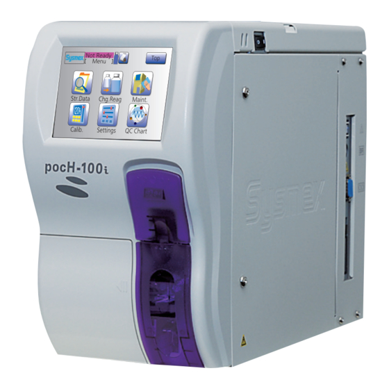
1.1. SYSTEM OVERVIEW 1.1.1. The instrument Before starting setup and analysis, please read through the following overview to get familiar with the instrument‘s parts and their description. Color LCD screen System fuses AC power supply AC 100 V AC 240 V Open button Contrast adjustment knob Float switch connector... - Page 10 9-pin D-SUB serial interface connector (communication with host computer, etc.) Card slot Rinse cup Inserts a program card specified Rinses the piercer (pipette) to by Sysmex. avoid sample-to-sample carry- over. Detector RBC transducer, WBC transducer and Hemoglobin detector 1 - 3...
-
Page 11: The Reagents
0.2 g/L Lysing reagent (purple) is max. 60 days. coagulant. • Reagent for lysing RBC for ac- Use at 15-30 °C. • Use pocH-pack 65/pocH-pack 65XL only with Lysing reagent (purple) curate WBC count and hemo- Sysmex reagents and analyzers. • Sodium Chloride 0.6g/L globin determination • The performance of Sysmex instruments cannot • The reagent is colorless, trans- be guaranteed if using other reagents. • Org. quart. ammoniumsalt parent and contains no cyanide. - Page 12 • Use opened reagent within 60 Incorrect analysis results (pipette) and the Hgb flow cell. days. • Use CELLCLEAN only with Sysmex reagents and CELLCLEAN analyzers. • The performance of Sysmex instruments cannot be guaranteed if using other detergent.
-
Page 13: Technical Information
1.2. TECHNICAL INFOR MATION 1.2.1. Performance characteristic - Specifications 15 °C to 30 °C (ideal operating temperature at 23 °C) Ambient temperature (59 °F – 86 °F) Relative humidity 30% to 85% Width: 185 mm (7 .3 in) Depth: 460 mm (18.1 in) Main Unit dimensions Height: 350 mm (13.8 in) - Page 14 1.2. TECHNICAL INFORMATION 1.2.1. Performance characteristic - Specifications Parameter Whole blood mode Pre-diluted mode WBC (≥ 4.0× 10 /μL) 3.5% or less 6.0% or less RBC (≥ 3.00 × 10 /μL) 2.0% or less 3.0% or less 1.5% or less 2.5% or less 2.0% or less 3.0% or less...
-
Page 15: System Limitations - Interferences
3% or less 1.5% or less Carry-over 1.5% or less 1.5% or less 5% or less Reagents: pocH-pack 65/pocH-pack 65XL Consumables Detergent: CELLCLEAN Control material: EIGHTCHECK-3WP in whole blood mode: approx. 15 μL Aspirated sample volume in pre-diluted mode: approx. 200 μL of the diluted sample; a minimum of 20 μL capillary blood is required. Number of analyses that can be per- pocH-pack 65: Approximately 65 formed with 1 pocH-pack 65/pocH-pack... -
Page 16: Setup
963-0801-5 dust-free location. 033-0414-2 - D evice must be protected against water. • Safety instructions for installation - Do not expose the instrument to excessive tem- Sample tube adapter Container spout kit Screwdriver (+) perature fluctuation and direct sunlight. 13 mm Sysmex white No.6 A6002 Philips - Avoid shock and vibrations. CJ296916 blue (Diluent) 462-2387-0 - The installation location must be well ventilated. 033-0403-1 for pocH-pack 65 - Avoid installation near devices causing potential 033-0405-9 for pocH-pack 65XL... -
Page 17: Optional Adapters
1.3.2. Optional adapters Adapter name Product code Adapter color Important Micro tube adapter • When using micro tubes, be sure to place them in CA392678 Orange (BD Microtainer tube with EDTA, Product No. 365975) the correct adapter. • Be sure to remove the cap. Micro tube adapter CH515979 Purple (BD Microtainer tube with EDTA, Product No. 365955) Micro tube adapter CE466834 Yellow... -
Page 18: Insert Paper Roll
1.3. SETUP 1.3.3. Insert paper roll Open the paper holder. Close the pepar holder. Warning, Hot The printer head can get very hot. Do not touch! Important Static electricity may damage the printer head. Do not touch. Insert the paper correctly. If inserted at an an- Open paper holder by pushing the knob. -
Page 19: Connect The Poch-Pack 65/Poch-Pack 65Xl
1.3.4. Connect the pocH-pack 65/pocH-pack 65XL pocH-pack 65 pocH-pack 65XL Biological risks Set the reagents and remove caps. Set the reagents and remove caps. Fix tubes together. To avoid infections, wear protective garments and gloves for cleaning and/or maintenance. After completion of work, wash hands with disinfectant. -
Page 20: Barcode Reader (Optional)
1.3. SETUP 1.3.5. Barcode reader (optional) Scans the barcode on the sample collection tube and automatically enters the sample number into the system. Plug cable into "BR" connection. Important • Disconnect the instrument‘s mains before con- necting the peripheral device. Else, the two de- vices may not interchange any data. • In identifying patient samples, maximum integrity of data is required. -
Page 21: Power Cord
1.3.6. Power cord 1.3.7. Switch ON When the main switch is turned ON the first time, supply the reagents into the instrument. Insert cable into socket. Switch ON. Note Danger, electric shock In this section, only the settings relevant Improper grounding of the instrument for installation are described. -
Page 22: Set Language
1.3. SETUP 1.3.8. Set language Default setting is English. After completion of the shutdown process, Switch OFF . Press "Menu". Select the language. Note In this section, only the settings relevant for instal- lation are described. For details on all possible set- tings see "Settings &... -
Page 23: Date & Time
1.3.9. Date & Time To be able to identify analysis results properly, set time and date correctly. Press "Menu". Choose Format. Note • In this section, only the settings relevant for in- stallation are described. For details on all possible settings see "Settings & Calibration" page 5-1. • When time switches to "standard or daylight sav- ing time"... -
Page 24: Lcd Contrast
1.3. SETUP 1.3.10. LCD contrast Adjust the LCD contrast to your comfort. Open front cover. Important If no operation is performed on the LCD screen for a certain period of time, the LCD backlight will de- crease automatically to save power (backlight sav- ing timer function). -
Page 25: Sample Collection Tube
1.3.11. Sample collection tube S-MONOVETTE (SARSTEDT) tube has a different bottom shape compared to the other sample tubes. Press "Menu". Press "Tube". Important • When SARSTEDT is selected, use "S-MONOVETTE EDTA K" collection tubes manufactured by SARSTEDT. • S-MONOVETTE (SARSTEDT) sample collection tubes cannot be used together with other sample collection tubes. If this is ignored, the instrument will not work. Press "Menu". - Page 26 Analysis in pre-diluted blood (PD) mode 2.1.7. Display analysis results 2-11 2.1.8. Histogram flags 2-12 2.1.9. Stored data 2-13 2.1.10. Print automatically stored data 2-14 2.1.11. Send data to host computer 2-14 2.1.12. Shutdown 2-15 2 - 1 pocH-100i Revised February 2011...
-
Page 27: Analysis
2.1. ANALYSIS 2.1.1. Screen display The LCD screen shows the available functions and submenus. Screen name Important The alarm can be stopped by pressing "OK" on the error dialog box. Pressing the -button displays Remaining reagent volume indicator the help menu. All other buttons are not functional during an alarm. -
Page 28: Numerical Keys Dialog
If you want to enter two letters which are located on the same button one after another, confirm your input by pressing "Ent." after entering the first letter. For example: desired input "AB". Ent. Ent. 2 - 3 pocH-100i Revised June 2008... -
Page 29: Prior To Analysis
2.1.4. Prior to analysis Check the power cable connection. Switch ON. Important Use only printer paper recommended by Sysmex. Low quality paper may shorten the life of the Perform mandatory quality printer head. check prior to operation. See "Quality control" page 3-1. -
Page 30: A) Analysis In Whole Blood (Wb) Mode
Analysis results are automatically printed/ Press the -button or press "Operator". Open sample position. Insert sample tube and close the door. ( sent to hos t computer according to settings(from page 5-2). 2 - 5 pocH-100i Revised February 2011... - Page 31 Incorrect analysis results All performance data cited in this manual were generated using specimens in EDTA anticoagulant. Results may differ using other anticoagulants. Important • When using micro tubes, place them in the cor- rect adapter and make sure the cap is removed. •...
-
Page 32: B) Analysis In Whole Blood (Wb) Mode
(from page 5-2). Open sample position. Mix the sample. Press "RUN". Open sample position. Gently mix the sample. Press "RUN". The sample tube caps have to be removed before measurement. 2 - 7 pocH-100i Revised February 2011... - Page 33 Incorrect analysis results All performance data cited in this manual were generated using specimens in EDTA anticoagulant. Results may differ using other anticoagulants. Important • When using micro tubes, place them in the cor- rect adapter and make sure the cap is removed. •...
-
Page 34: Analysis In Pre-Diluted Blood (Pd) Mode
-button or press "Operator". and close door. tube and mix gently. Open sample position. Press "Execute". Press "PD". Open sample position. Press "Execute". Press "PD". 500 μL of diluent are dispensed into the tube. 2 - 9 pocH-100i Revised February 2011... - Page 35 Remove the cap, set sample into Analysis results are automatical- Select a operator ID . the adapter and close the door. ly printed according to settings. Incorrect analysis results • All performance data cited in this manual were generated using specimens in EDTA anticoagulant. Results may differ using other anticoagulants.
-
Page 36: Display Analysis Results
W-MCC and W-LCC parameters. Fourth screen Displays analysis results of RBC, MCV, RDW-SD, RDW-CV, PLT, PDW, MPV, and P-LCR parameters. Volume distribution flag see "Histogram flags" page 2-12 Press arrow to switch to fourth screen. 2-11 pocH-100i Revised February 2011... -
Page 37: Histogram Flags
2.1.8. Histogram flags The pocH-100 extracts the characteristics of the histogram and displays them as histogram flags. If there are histogram flags, repeat analysis. If flags are still displayed, one of the following problems may apply. Correction Flag Probable sample cause Warm sample Wash Check... -
Page 38: Stored Data
RBC, MCV, RDW-SD, RDW-CV, PLT, PDW, MPV, P-LCR Choose stored data (cursor sample). Switch Switch to second, third and fourth stored to second list screen for current cursor sam- data screen by pressing " ". ple by pressing " ". 2 -13 pocH-100i Revised February 2011... -
Page 39: Print Automatically Stored Data
2.1.10. Print automatically stored data 2.1.11. Send data to host computer Stored data can be sent to host computer via serial port or LAN. Press "Menu". Press "Menu". Press "Menu". Press "Menu". Press "Str. Data". Press "Str. Data". Press "Str. Data". Press "Str. -
Page 40: Shutdown
Execute a shutdown at least every 24 hours. This may prevent damage to the instrument. Press "Execute". Switch OFF . Press "Execute". Switch OFF the instrument. Shutdown begins. Shutdown begins. Process takes approx. 2 min. 2 -15 pocH-100i Revised February 2011... - Page 41 2 -16 pocH-100 Revised February 2011...
- Page 42 3. QUALITY CONTROL : CONTENTS 3.1. QUALITY CONTROL 3.1.1. Quality control chart screen 3.1.2. Print control chart 3.1.3. Output to host computer 3.1.4. Delete data 3.2. PERFORMING QUALITY CONTROL 3.2.1. STEP 1: a) Settings for control blood information (quality control file) b) Automatic settings 3.2.2.
-
Page 43: Quality Control
3.1. QUALITY CONTROL 3.1.1. Quality control chart screen First chart screen Press "Menu". Expiration date Lot ID Date/Time of analysis Chart Press "Menu". Data for following parameters Press "QC". First chart screen WBC, RBC Second chart screen HGB, HCT Third chart screen MCV, MCH Fourth chart screen MCHC, PLT... -
Page 44: Print Control Chart
3.1. QUALITY CONTROL 3.1.2. Print control chart 3.1.3. Output to host computer Press "Menu". Press "Chart" or "Current". Press "Menu". Output to computer. Serial port (RS-232C) or (Ethernet). Press "Menu". Press "Menu". Output to computer. Press "Chart" to print charts of all param- eters or "Current"... -
Page 45: Delete Data
3.1.4. Delete data Press "Menu". Press "OK". Press "Menu". Press "OK". Press "QC". Press "QC". Press "Delete". Press "Delete". 3 - 4 pocH-100 Revised June 2008... -
Page 46: Performing Quality Control
3.2. PERFORMING QUALITY CONTROL 3.2.1. STEP 1: a) Settings for control blood information (quality control file) Enter "Lot ID" and "Expire", then Press "Menu". press " ". Press "Save". Incorrect analysis results The operator must ensure the control blood is not beyond expiration date. -
Page 47: B) Automatic Settings
3.2.1. STEP 1: b) Automatic settings Enter "Lot ID" and "Expire", then Press "Menu". Press "A.Lmt". Press "Save". press " ". Press "Menu". Enter "Lot ID" and "Expire" manually or by Press "A.Lmt". (Automatic calculation of 2SD After completion of automatic calculation of barcode reader. -
Page 48: Step 2: Preparing Control Blood
For further information see "The reagents" page 15 minutes before use. 1-4. • I f other control materials are used, the product performance of Sysmex instruments cannot be Examine vial bottom. If there guaranteed. is a cells pellet on the bot- tom, repeat whole proce-... - Page 49 3 - 8 pocH-100 Revised June 2008...
-
Page 50: B) Performing Quality Control: X _ Method (For Close Piercer)
3.2. PERFORMING QUALITY CONTROL 3.2.3. STEP 3: a) Performing quality control: L-J method (factory setting) (for close piercer) Daily Press the -button or press "Operator". Press "QC". Insert adapter. The analysis starts. Press the -button or press "Operator". Press "QC". Insert correct adapter. - Page 51 Biological risks • Wear protective garments and gloves. • Disinfect hands after work. Important • Do not open the sample position while aspirating! • Make sure that there are no objects underneath the sample position, because otherwise it cannot be opened fully. • Use only the supplied sample adapter. Failure to do so may result in serious damage of the instru- ment. Note The analysis results are automatically saved to "stored data". 3-10 pocH-100 Revised June 2008...
- Page 52 3.2. PERFORMING QUALITY CONTROL 3.2.3. STEP 3: a) Performing quality control: L-J method (factory setting) (for open pipette) Daily Insert control blood and close Press " " or " " to scroll Press "QC". the door. screens. Set the spacer to an adapter. Press "QC".
- Page 53 Biological risks • Wear protective garments and gloves. • Disinfect hands after work. Important • Do not open the sample position while aspirating! • Make sure that there are no objects underneath the sample position, because otherwise it cannot be opened fully. • Use only the supplied sample adapter. Failure to do so may result in serious damage of the instrument. • When a sample tube with a cap is used, manually remove the cap before analysis. The pipette might be permanently damaged, if the cap was not removed.
- Page 54 3.2. PERFORMING QUALITY CONTROL 3.2.3. STEP 3: b) Performing quality control: X method (for close piercer) Daily Press "Next" to perform the sec- Press the -button or press "Operator". Insert adapter. Press "QC". ond analysis. Insert correct adapter. Press the -button or press "Operator".
- Page 55 The final results appear. Biological risks • Wear protective garments and gloves. • Disinfect hands after work. Important • Do not open the sample position while aspirating! • Make sure that there are no objects underneath the sample position, because otherwise it cannot The final results appear. Scroll the results be opened fully. by pressing " "or " " and press "Print". • Use only the supplied sample adapter. Failure to do so may result in serious damage of the instru- ment.
-
Page 56: Performing Quality Control: X Method (For Open Pipette)
3.2. PERFORMING QUALITY CONTROL 3.2.3. STEP 3: b) Performing quality control: X method (for open pipette) Daily Insert control blood and close Mix well and insert it back into Set the spacer to an adapter. Press "QC". the door. the sample position. Press "QC". - Page 57 Biological risks • Wear protective garments and gloves. • Disinfect hands after work. Important • Do not open the sample position while aspirat- ing! • Make sure that there are no objects under- neath the sample position, because otherwise it cannot be opened fully. • Use only the supplied sample adapter. Failure to do so may result in serious damage of the instrument. • When a sample tube with a cap is used, manu- ally remove the cap before analysis.
- Page 58 4. CLEANING & MAINTENANCE : CONTENTS 4.1. CLEANING 4.1.1. Clean instrument surface 4.1.2. Check instrument status 4.1.3. Shutdown 4.1.4. Clean transducer 4.1.5. Clean waste chamber 4.1.6. Clean the sample tube adapter 4.1.7. Perform auto rinse 4.1.8. Remove clog from transducer aperture 4.1.9.
-
Page 59: Cleaning
4.1. CLEANING 4.1.1. Clean instrument surface • When cleaning the instrument surface or the touch panel, use a "soft dry cloth", "cloth soaked in neutral detergent then wrung tightly", or "soft cloth dampened with ethanol". • Do not use any organic solvent, acid, or alkaline agent. T hese will affect the instrument surface‘s finish and may cause corrosion or discoloration. 4.1.2. Check instrument status Check operation counter, program version and other information before contacting your Sysmex Service representative. Press "Menu". The screen displays information. Biological risks To avoid infections, wear protective garments and gloves for cleaning and/or maintenance. After com- pletion of work, wash hands with disinfectant. Important • To ensure proper functioning of the instrument, periodical cleaning and servicing is necessary. The following information is displayed on Press "Menu". ( • Security Information for Using CELLCLEAN:... -
Page 60: Shutdown
4.1. CLEANING 4.1.3. Shutdown Removes deposits in the instruments tubing. Daily Follow instructions on the screen. Press "Shutdown". Then switch OFF. Incorrect analysis results • Deposits in the instrument‘s tubing can cause incorrect analysis results. Therefore, the trans- ducer chambers and diluted sample tubes must be cleaned. • If the instrument is used continuously without performing the shutdown sequence, protein clot- ting may cause incorrect analysis results or it may damage the instrument. -
Page 61: Clean Transducer
4.1.4. Clean transducer Even if the message "Clean T ransducer" is not displayed, this maintenance can be executed by pressing "Menu", "Maint." and then "Clean T ransducer". Every 2 weeks or 150 samples Cleaning instruction message is displayed. Insert adapter. Process begins. Note A message will appear when either the counter value exceeds 150 or 2 weeks have passed since the last cleaning of the transducer. . After cleaning, the counter resets automati- cally. -
Page 62: Clean Waste Chamber
4.1. CLEANING 4.1.5. Clean waste chamber Even if the message "Clean waste chamber" is not displayed, this maintenance can be executed by pressing "Menu", "Maint." and then "Clean waste chamber". Every 3 months or 1500 samples Cleaning instruction message is displayed. Insert adapter. Process begins. Note • A message will appear if either the counter value exceeds 1500 or 3 months have passed since the last "Clean waste chamber". • After cleaning, the counter resets automatically. Cleaning instruction message is displayed. Insert adapter. Process begins. Afterwards "Auto Rinse" and "Background check" will be performed automatically. Add 3mL of CELLCLEAN into the Set CELLCLEAN in place, close Cleaning completed. -
Page 63: Clean The Sample Tube Adapter
4.1.6. Clean the sample tube adapter 4.1.7. Perform auto rinse If sample has spilt into the adapter. Clean tubings and drain waste. Even if the message "Auto Rinse" is not displayed, auto rinse can be executed by pressing "Menu", "Maint." and then "Auto Rinse". As needed As needed Switch OFF . Press "Execute". Biological risks Always wear protective garments and gloves when handling the waste fluid. After work is completed, wash hands with disinfectant. Switch OFF . Press "Execute". -
Page 64: Remove Clog From Transducer Aperture
4.1. CLEANING 4.1.8. Remove clog from transducer aperture If an "Aperture Clog" error occurs, the clog must be removed. Even if the message "Aperture Clog" is not displayed, automatic clog removal can be executed by pressing "Menu", "Maint." and then "Clog Removal". As needed Press "Execute". Note . To return to the main screen with- out performing automatic clog re- moval, press "Cancel". Press "Execute";automatic clog removal starts. ( 4 - 7 pocH-100 Revised June 2008... -
Page 65: Dispose Waste Fluid
4.1. CLEANING 4.1.9. Dispose waste fluid If the "Discard waste" error message appears, the waste bottle is full and needs to be emptied. The waste bottle might be necessary in case of using pocH-pack 65XL. As needed The screen displays "Discard waste. ” Waste discharge operation starts. Biological risks • Always wear protective garments and gloves when handling the waste fluid. After work is completed, wash hands with disinfectant; • Dispose waste fluid appropriately in accordance to local laws and regulations; • Ensure that the waste bottle is secure and prop- erly connected before operating the instrument. -
Page 66: Drain Reagents
4.1.10. Drain reagents Perform before moving/shipping the instrument. As needed Remove spout kits from diluent and lysing reagent. Press "Deprime Seq.". The screen of process completed. Biological risks Always wear protective garments and gloves when handling the waste fluid. After work is com- pleted, wash hands with disinfectant. Note • Place the removed container spout kits on top of a clean cloth or inside a plastic bag, and shield from dust. Remove spout kits from diluent and lysing Press "Deprime Seq.". -
Page 67: Calibrate Lcd
4.1. CLEANING 4.1.11. Calibrate LCD Calibrate the LCD if panel operation is not properly aligned. As needed Press "Menu". Press the centre of the plus 5 times. Important When calibration is performed and a calibration er- ror occurs frequently, there may be a problem with the touch screen. In this case contact your Sysmex service representative for assistance. Note If the input position was outside a regulated range, the calibration error message will appear, and the Touch "+" each time it is displayed on the Press "Menu". screen (5 times). calibration will be discontinued. Press "Maint.". Press "OK". Press "Maint.". -
Page 68: Replace Thermal Printer Paper
4.1.12. Replace thermal printer paper Only use paper recommended by Sysmex. As needed Open the paper holder. Close lid and remove excess paper. Warning, Hot Do not touch the printer head! It can get very hot. Important Static electricity may damage the printer head. Do not touch. Note Open paper holder by pushing the knob. Close lid and remove excess paper. The printer cover must be closed (clicking sound). If the cover is not closed completely, an error mes- Remove the tape. sage will be displayed. Insert the paper correctly. If inserted at an angle, the paper might jam. Remove the tape. Insert paper. Insert paper. ( 4 - 11... -
Page 69: Replace Reagent
4.1. CLEANING 4.1.13. Replace reagent As needed Enter reagent barcode by bar- The screen displays "Replace code reader and proceed to step pocH-pack65". 7 or press "Manual". Press "Execute". Biological risks When handling (disposing) the waste fluid,dispose it appropriately in accordance to local laws and regulations, which considers for the disposal of medical waste and infectious waste. -
Page 70: Technical Maintenance-Qualified Personnel Only
4.2. TECHNICAL MAINTENANCE-Qualified personnel only! 4.2.1. Clean aperture of TD chamber If the clogging of the aperture cannot be removed by the automated sequence, the aperture must be cleaned manually with the transducer brush. As needed Open side cover and open detec- Press "Menu". Press "Execute". Switch OFF . tor cover. Press "Menu". Press "Execute". Switch OFF . Open side cover and open detector cover. Press "Maint.". Process starts. Disconnect power cord. Check if fluid has not been drained. - Page 71 Clean aperture gently. Biological risks Always wear protective garments and gloves for all service and maintenance work. Use only speci- fied tools and parts. After completion of work, wash hands with disinfectant. Instruments that got in contact with blood have infectious potential. Danger, electric shock Apply CELLCLEAN to transducer brush, Re-attach the transducer chamber plug securely. clean aperture gently. Otherwise, reagent leakage might occur, which may cause a short circuit or electrical shock. Close all covers. Tighten the screws. Important If performing maintenance work, use only the specified tools and parts. Install only such spare or...
-
Page 72: System Fuse Replacement
4.2. TECHNICAL MAINTENANCE-Qualified personnel only! 4.2.2. System fuse replacement As needed Switch OFF . Replace the fuse(s). Danger, electric shock To avoid electrical shock, disconnect power supply before servicing. Important Replace only with fuse of the specified type and correct current specifications. Switch OFF . Remove fuse holder cap. Replace fuse(s). Put fuse holder cap back in place. Unplug power cable. Switch ON. - Page 73 4 -16 pocH-100 Revised June 2008...
- Page 74 5. SETTINGS & CALIBRATION : CONTENTS 5.1. SETTINGS 5.1.1. Change settings 5.1.2. Possible settings 5.1.2.1. System setup 5.1.2.2. Date/Time 5.1.2.3. Patient Limits 5.1.2.4. QC settings 5.1.2.5. User information settings 5.1.2.6. Host settings 5.1.2.7. Printer settings 5.1.2.8. Network settings 5.1.2.9. Password setting 5.1.2.10.
-
Page 75: Settings
5.1. SETTINGS Set up the instrument according to your personal needs or to laboratory requirements. 5.1.1. Change settings Some parameters are set by factory default. Others (Date/Time) have to be set on initial operation. Press "Menu". Press "Save". Note See "Possible settings" pages 5-3~5-10 for more detailed information on parameters that can be set manually. -
Page 76: Possible Settings
5.1. SETTINGS 5.1.2. Possible settings 5.1.2.1. System setup Press "Menu" > "Settings" > Important "System". It is not possible to convert the stored data from Dutch SI units to other units for the following 3 pa- rameters: HGB, MCH, MCHC. Do not use stored sample data which was saved before changing the settings. -
Page 77: Date/Time
5.1.2.3. Patient Limits 5.1.2.2. Date/Time Enter the upper and lower limit marks for the patient results. For standard or daylight saving time, the clock must be set manually. Press "Menu" > "Settings" > Press "Menu" > "Settings" > "Pa- Note Note "Date/Time". -
Page 78: Qc Settings
5.1. SETTINGS 5.1.2.5. User information settings 5.1.2.4. QC settings If several pocH-100 are connected to a host computer, a unique naming can be set to identify each Select Quality Control and data output method. instrument. Press "Menu" > "Settings" > Press "Menu"... -
Page 79: Host Settings
5.1.2.6. Host settings To set data output to host computer. Press "Menu" > "Settings" > Note "Host Output". The underscored items are factory settings. Press "Menu" > "Settings" > "Host Output". Parameter Setting Disable / Serial / LAN Connect Enable / Disable Automatic Output pocH... -
Page 80: Printer Settings
5.1. SETTINGS 5.1.2.7. Printer settings Printing out analysis results can be set here. The print header can be set individually ( i.e. containing laboratory name, instrument name etc.) Press "Menu" > "Settings" > "Built-in Printer". Parameter Setting Note Automatic Print All Data / Error Data / Disable The underscored items are factory set-... -
Page 81: Network Settings
5.1.2.8. Network settings Address and other necessary settings can be entered for use of LAN port to communicate with a host computer. In addition, the MAC address can be viewed on this screen. Press "Menu" > "Settings" > "Network". Note The underscored items are factory settings. -
Page 82: Password Setting
Press "Menu". Enter password and press "Ent.". Important • In case the password has been forgotten, contact your Sysmex service representative. • Enter maximum 10 digits of numerals (0-9) or hy- phens (-) . Press "Menu" > "Settings" > "Password Set- Press "Menu". -
Page 83: Print Settings
5.1.2.10. Print settings Print a list of the current settings. Press "Menu" > "Settings" > "Print Settings". Press "Menu" > "Settings" > "Print Settings". 5 -10 pocH-100 Revised June 2008... -
Page 84: Calibration
5.2. CALIBRATION The HGB and/ or HCT values are corrected by a calibration value. 5.2.1. Calibrate the instrument • If quality control shows repeated deviations in the same direction. • If a major component of the instrument has been replaced. Establishing reference values Important Recommended measuring methods:... -
Page 85: Automatic Calibration
5.2.2. Automatic calibration The instrument determines the calibration value automatically by analyzing 5 calibration samples. Enter reference values and press Important Press "Menu". "Ent.". Press "Quit.". • Automatic calibration is always performed in the WB mode. • It is important to analyze the samples according to their reference values. -
Page 86: Manual Calibration
5.2. CALIBRATION 5.2.3. Manual calibration The calibration value must be calculated according to the formula shown below and entered manually. Use normal and fresh blood of 5 or more samples. Note 1. Establish the reference values. A calibration error is displayed, if the mean calibra- 2. -
Page 87: Print Calibration History
5.2.4. Print calibration history Print an overview of the five most recent calibration results. Press "Menu". Press "Menu". Press "Calib.". Press "Calib.". Press "Print Cal. His.". Press "Print Cal. His.". 5 -14 pocH-100 Revised June 2008... - Page 88 6. TROUBLESHOOTING : CONTENTS 6.1. GENERAL ERRORS, INSTRUMENT FAILURE 6.2. ERROR MESSAGES ERROR MESSAGES, POSSIBLE CAUSES AND ACTIONS TO RESOLVE THE ERROR 6-4 6.3. Vacuum Error Waste C. Error Replace pocH-pack 65 Drain Error Piercer MC Error / PinchV1 MC Error / PinchV2 MC Error / Syringe MC Error Piercer MT Error / Syringe MT Error PinchV1 MT Error Aperture Clog...
- Page 89 Mechanical operation is heard, but ment. Check whether the LCD screen contrast is set correctly. no display appears on LCD screen. Note Fluid leaks from the instrument. Turn the main power switch OFF and wipe off the leaked fluid. If the instrument shows a malfunction, check the following table. If the corresponding item is not found or the procedure listed does not eliminate the problem, contact your Sysmex service repre- sentative. • Other errors are indicated by a beep and a mes- sage displayed on the LCD screen. • If an error affects only a specific analysis result, it will be marked by a flag. 6 - 2 pocH-100 Revised June 2008...
- Page 90 Error dialog. Important • If you are unable to solve the problem, contact your Sysmex service representative for assistance. Please note the ERROR CODE to enable your ser- vice representative to provide quick assistance. • In case of a power failure during operation, turn the main power switch OFF .
- Page 91 6.3. ERROR MESSAGES, POSSIBLE CAUSES AND ACTIONS TO RESOLVE THE ERROR Vacuum Error Drain Error Possible cause The waste bottle is full. Defective vacuum pump or air leakage in vacuum line. Possible cause • See "Dispose waste fluid" page 4-8. • Check if any fluid was collected in the trap chamber. Action to resolve the error • After checking, press "Execute" to clear the error, and the • Press "Execute" to clear the error and perform the recovery recovery sequence is executed.
- Page 92 6.3. ERROR MESSAGES, POSSIBLE CAUSES AND ACTIONS TO RESOLVE THE ERROR PinchV1 MT Error Blank Error Operation of driving motor is abnormal. The tube is stuck or • Instrument has not been operated for several days. Possible cause broken. • Aperture clogged. Possible cause • Dirty HGB flow cell. • Air trapped in the system. Action to resolve the error Turn the main switch OFF , then turn it ON again.
- Page 93 PLT Smp’g Error RBC Smp’g Error WBC Smp’g Error RAM and ROM Error • Aperture partly clogged. Possible cause • Air bubbles sticking in transducer aperture. CPU malfunction due to momentary power failure, sudden Possible cause • Effect of external electric noise interference. electric noise interference, etc. • Remove the aperture clog. Execute automatic clog removal Action to resolve the error Turn the main switch OFF , then turn it ON again.
- Page 94 6.3. ERROR MESSAGES, POSSIBLE CAUSES AND ACTIONS TO RESOLVE THE ERROR HC Buffer Full LAN Buffer Full Print Buffer Full R-Cover open The amount of data for output or printout is too large to be Possible cause The right side cover was opened. Possible cause processed.
- Page 95 HC ACK Timeout HC Off-line HC NAK Retry • Computer connection cable failure. • Computer main switch is not turned on, or computer not Possible cause ready for communication. • Host computer serial interface error. • Inspect the host computer‘s cable. • Inspect the connection cable to host. • Press "Retry" to clear the error, and the transmission to the Action to resolve the error host computer is restarted. • Press "Cancel" to clear the error. All output queued to host computer is deleted. Not ready until the error is resolved. If the retry action does Special notes, if error re- not resolve the problem, take the host transmission off-line in mains...
- Page 96 6.4. PRINT ERROR LOG The 10 most recent error messages are printed. Press "Menu". Note Print error messages prior to contacting your Sysmex service representative. Press "Menu". Press "Maint.". Press "Maint.". Print out error history. Press "Print Error Log"; the error history will be printed out.
- Page 97 6-10 pocH-100 Revised June 2008...
- Page 98 7. SAFETY INFORMATION & WASTE DISPOSAL : CONTENTS 7.1. SAFETY INFORMATION 7.1.1. General information 7.1.2. Measures for personnel 7.1.3. Hazards of electricity 7.1.4. Biohazards 7.1.5. Handling of reagent 7.1.6. Warning labels on the instrument 7.1.7. Electromagnetic compatibility (EMC) 7.2. WASTE DISPOSAL 7.2.1.
-
Page 99: Safety Information
• Never touch waste or parts having been in contact with waste with your bare hands. • If the instrument service is required, contact your Sysmex representative. • Should you inadvertently come in contact with potentially infectious materials or surfaces, im- •... -
Page 100: Handling Of Reagent
7.1. SAFETY INFORMATION 7.1.5. Handling of reagent Incorrect handling of reagents can cause incorrect analysis results! • Store the reagents at their specified temperatures. • Do not use reagents after their expiration date. • Do not shake! Do not use directly after transport. Handle reagents gently to avoid bubbling. -
Page 101: Warning Labels On The Instrument
7.1.6. Warning labels on the instrument Warning Warning, Hot Warning • This equipment must be grounded. The printer head may get very hot. When opening the detector cover to clean the trans- • To avoid electrical shock, disconnect supply before ducer aperture, follow the instructions in chapter "Clean servicing. -
Page 102: Electromagnetic Compatibility (Emc)
7.1. SAFETY INFORMATION 7.1.7. Electromagnetic compatibility (EMC) This instrument complies to the following IEC(EN) standards: • IEC61326-1:1997+A1:1998+A2:2000 (EN61326:97+A1) Equipment for measurement, control and laboratory use EMC Require- ments. • EMS (Electro-magnetic susceptibility (= interference radiation)) For this issue the industrial environment requirements with regards to im- munity are fulfilled. -
Page 103: Waste Disposal
• Do not dispose the instrument, accessories and consumables via public recycling! • Incineration of contaminated parts is recommended! • Contact your local Sysmex service representative and receive further instructions for disposal! Follow local legal requirements at all times. 7 - 6... - Page 104 8. INDEX Preparing control blood …………………………… 3-7 Print automatically stored data …………………… 2-14 Abbreviations …………………………………………… 2 Functional description ………………………………… 3 Print calibration history …………………………… 5-14 Accessories (Waste disposal) ……………………… 7-6 Print control chart …………………………………… 3-3 Addresses ………………………………………………… 1 Print error log ………………………………………… 6-9 Alphabetical keys dialog ……………………………...
- Page 105 8 - 2 pocH-100i Revised June 2008...
Need help?
Do you have a question about the pocH-100i and is the answer not in the manual?
Questions and answers
Как правильно выключить прибор?
I'm using this machine symex poch 100i.Barcod from reagent doesn't recognized to the machine how can I get help from you in order to use this machine please
what are the humidity range requirements?