
Subscribe to Our Youtube Channel
Related Manuals for SYSMEX CyFlow Ploidy Analyser


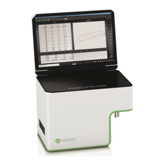
Summary of Contents for SYSMEX CyFlow Ploidy Analyser
- Page 1 CyFlow™ Ploidy Analyser Operating Manual With CyView™ 1.8 Doc. No.: CY-S-3039IFUEN | Rev: 006 | Rev. date: 27-10-2021 | EN | CN 1434...
-
Page 3: Table Of Contents
Typographical conventions ................9 2.2.1 Safety information ....................9 2.2.2 Text highlights ....................10 General conditions ................... 11 CE compliance ....................11 Sysmex representatives .................. 12 Authorised distributors ..................12 Safety ......................13 Intended Use ....................13 Prohibited use ....................13 Reasonably foreseeable misuse .............. - Page 4 Table of contents Installation and uninstallation ................24 Operation ....................... 25 7.1.1 Switching on the device ................... 25 7.1.2 Logging in ......................26 7.1.3 Priming the device ................... 26 Running a Quality Check ................. 27 Performing a measurement (Sample Port) ............27 Saving acquired data ..................
- Page 5 Table of contents 11.3.1 Device cleaning ....................44 11.4 Technical service ..................... 45 11.4.1 Preventive maintenance .................. 45 11.4.2 Defective device ....................45 Disposal ......................46 12.1 Disposal of device ................... 46 12.2 Disposal of components .................. 46 12.3 Waste disposal ....................46 12.4 Sheath Fluid disposal ..................
- Page 6 Table of figures Table of figures Figure 1: Front and left side of the device ............... 17 Figure 2: Ports for external devices ................. 18 Figure 3: Rear side of the device..................18 Figure 4: Sample port at the right side of the device ............19 Figure 5: Type plate ......................
-
Page 7: Identification
CyFlow™ Ploidy Analyser Name CyView™ 1.8 Software CY-S-3039 Versions CY-S-3039_V1 CY-S-3039_V2 CY-S-3039_V3 1.2 Manufacturer Sysmex Partec GmbH Arndtstraße 11 a-b, 02826 Görlitz, Germany Phone +49 3581 8746-0 Fax +49 3581 8746-70 info@sysmex-partec.com www.sysmex-partec.com CyFlow™ Ploidy Analyser | Operating Manual | October 2021... -
Page 8: Introduction
Please also refer to these documents. If you have any questions about the content of this manual or the use of the device, contact your local Sysmex representative. CyFlow™ Ploidy Analyser | Operating Manual | October 2021... -
Page 9: Typographical Conventions
2 Introduction 2.2 Typographical conventions 2.2.1 Safety information Safety information and warnings are marked by symbols and signal words. Hazards are categorised into four levels. All warnings are structured according to the same model. The type of hazard is stated after the signal word. Then the consequences that may result from the hazardous situation are described. -
Page 10: Text Highlights
Bold Describes headlines of subtopics, which need no independent chapter. Example: Qualified personnel Describes also specially highlighted keywords. Example: Names the source of the hazard Underlined References external hyperlinks. Example: www.sysmex-partec.com CyFlow™ Ploidy Analyser | Operating Manual | October 2021... -
Page 11: General Conditions
This Operating Manual must be read prior to using the device. • Report any recurring faults or problems to your local Sysmex representative. Sysmex Partec GmbH does not accept liability for any damage or personal injury arising from: • Unauthorised modifications or manipulation of the device;... -
Page 12: Sysmex Representatives
2 Introduction 2.5 Sysmex representatives Find address and contact data of your local Sysmex representative also at www.sysmex-partec.com. Table 2: Representatives contacts Europe, Middle East and Africa Sysmex Europe GmbH Bornbarch 1, 22848 Norderstedt, Germany Phone: +49 40 5 27 26-0 Web: www.sysmex-europe.com... -
Page 13: Safety
3 Safety 3.1 Intended Use The CyFlow Ploidy Analyser is equipped with a UV LED 365 nm emission wavelength and/or a Nd-YAG green laser 532 nm emission line. For fluorescence detection of DAPI (DAPI-DNA) a blue sensitive PMT is used which analyses fluorescent light between 435 nm and 560 nm. -
Page 14: User Qualification Groups
Instructed personnel have to be trained by qualified personnel or personnel authorised by Sysmex to operate the device within the scope of the intended use. They have to be able to assess if the device can be safely used and are proficient in handling hazardous substances. -
Page 15: Prohibition And Warning Signs On The Device
3 Safety 3.6 Prohibition and warning signs on the device The following prohibition and warning signs have been affixed to the device. Table 4: Safety signs on the device Symbol Description General hazards Laser radiation (Only for CY-S-3039_V2 and CY-S-3039_V3) Laser radiation (Only for CY-S-3039_V2 and CY-S-3039_V3) Additional laser labelling... -
Page 16: General Safety
Always meet the national and international guidelines and regulatory standards for PPE (personal protective equipment). Find Safety Data Sheets for our products at www.sysmex-partec.com. 3.9 Laser radiation hazards The device is equipped with a class IIIb laser unit. If the housing of the device is closed, the laser class of the laser unit is classified as a laser class I (EN 60825-1). -
Page 17: Overview
4 Overview 4 Overview 4.1 Device NOTICE Glass parts are fragile Objects put on the glass top or display of the device may damage or break the glass and do not scratch glass surfaces. • Do not place any objects on the glass top or display of the device. Your CyFlow™... -
Page 18: Figure 2: Ports For External Devices
4 Overview Figure 2: Ports for external devices Item Item Item USB port HDMI port Serial port Ethernet port USB port Ethernet port Audio port Audio port USB port USB port USB port DVI port Keyboard port Mouse port Figure 3: Rear side of the device Item Item Waste tubing connection Waste... -
Page 19: Components Of The Device
4 Overview Figure 4: Sample port at the right side of the device Item Item Start electrode Sample holder Stop electrode Sample port injection needle Sample tube 4.2 Components of the device The device contains the flow cuvette, the optics, the fluidics, the computer unit and data acquisition electronics. -
Page 20: Sample Port With Electrodes
4 Overview 4.2.4 Sample port with electrodes The Sample port is located on the right side of the device. It holds the Sample tube during the measurement. The start and stop electrodes of the Sample port allow the independent determination of exactly 200 μl volume for each sample. -
Page 21: Scope Of Delivery
4.3 Scope of delivery The scope of delivery lists all items delivered with the CyFlow™ Ploidy Analyser. All listed items are available through our website or your local Sysmex representative. 4.4 Scope of operation The scope of operation lists all items needed to operate the CyFlow™ Ploidy Analyser. -
Page 22: Reagents
Hypochlorite Solution 4.5 Reagents The table below lists the available reagents used on a CyFlow™ Ploidy Analyser. For a complete list of available reagents please visit our website or contact your local Sysmex representative. Table 8: Reagents Item Content REF No. -
Page 23: Accessories And Spare Parts
The table below lists the accessories and spare parts used on a CyFlow™ Ploidy Analyser. For a complete list of available accessories and spare parts please visit our website or contact your local Sysmex representative. Table 9: Accessories and spare parts Item Content REF No. -
Page 24: Installation
6 Installation 6 Installation 6.1 Positioning the device Carefully select the place where to position and operate the device, it should not be moved without disconnecting its components. Comply with the following criteria when positioning the device: • Place the device on a solid, dry and clean horizontal surface. •... -
Page 25: Operation
7 Operation 7 Operation The chapter operation contains all information necessary to operate your CyFlow™ Ploidy Analyser in a easy, safe and reliable way. It contains notes and information to simplify the operation of your CyFlow™ Ploidy Analyser. NOTICE Sheath Fluid Sheath Fluid affects the sample flow through the flow cuvette. -
Page 26: Logging In
If a CyFlow™ Robby 6 is connected and should be primed the measure settings for Settings - Measure Mode must be changed to Autoloader. • See Operating Manual CyFlow Ploidy Analyser with Robby 6 (CyView 1.6 SW) IFU GB EN Requirements •... -
Page 27: Running A Quality Check
7 Operation 7.2 Running a Quality Check The Quality Check (QC) procedure will guide the user through the Quality Check of CyFlow™ Ploidy Analyser with certain reagents For a detailed decription of the Quality Check procedure refer to the CyFlow™ Ploidy Analyser QC Manual. -
Page 28: Saving Acquired Data
7 Operation Recommendations • The sample volume is not less than 850 µl (minimum for TVAC). • Use flow rates between 0.5 - 5 µl/s for sample measurements. The optimal flow rates depends on the application. • Use the same flow rate for pre-measure and measure phase to avoid fluidic turbulences. -
Page 29: Performing Intermediate Cleaning
7 Operation Procedure 1. Select [Save (.fcs)]. 2. Choose a Storage folder and insert Sample name. 3. Click [Save]. For more information, please refer to chapter 13.3 Data management. 7.5 Performing intermediate cleaning A cleaning mode is available to clean the fluidic system of the device. Intermediate Cleaning: Choose the clean symbol in the right lower corner (Device Controls). -
Page 30: Switching Off The Device
For more information, please refer to chapter 13 Troubleshooting 7.8 Fault, cause and remedy If the fault you are experiencing is not described or the remedy could not solve your problem, please contact your local Sysmex representative. 7.8.1 Sheath Fluid, waste and other fluids Fault... - Page 31 7 Operation Fault Remedy Check if the visible Sheath Fluid tubing is pinched or blocked. Shut down the device, including the Power switch on the back of the device. Wait 3–5 minutes and re-start the system. Check the speed settings. CyFlow™...
-
Page 32: Calibration And Count Check Beads (Low, Medium, High)
7 Operation 7.8.2 Calibration and Count Check Beads (low, medium, high) Fault Remedy The result of Count Check Shake the bottle vigorously (e.g. by vortexing) and repeat Beads (low, medium, high) the measurement. measurement is not within Check the date of expiry of the Count Check Beads (low, ±... -
Page 33: Maintenance
8 Maintenance 8 Maintenance Servicing is to be performed by an authorised service engineer. Please contact your local Sysmex representative for further instructions. Table 12: Maintenance activities Activity Qualification requirement Regular maintenance Instructed personnel, Qualified personnel, Authorised service personnel Other maintenance... -
Page 34: Maintenance Procedures
8 Maintenance 8.2 Maintenance procedures 8.2.1 Sheath Fluid refilling NOTICE Bent Tubing When screwing or unscrewing a bottle and its respective cap, it is advantageous to twist the bottle instead of the cap. • The Tubing must stay unbent. Requirements •... -
Page 35: Other Maintenance
8 Maintenance 8.3 Other maintenance 8.3.1 Device cleaning WARNING Sample port electrodes The Sample port electrodes are most sensitive and are easily damageable, which causes incorrect measurement volume and therefore incorrect results. • Only Authorised service personnel must clean the Sample port and its components. -
Page 36: Technical Service
Preventive maintenance must be realised by Authorised service personnel of Sysmex only. 8.4.2 Defective device Treatment of defective devices can be realised at the installation site or at Sysmex localities. How to deal with the defective device is determined by how severe the errors are. -
Page 37: Disposal
9.1 Disposal of device Electrical and electronic equipment must be disposed of separately from normal waste. Please contact your local Sysmex representative, since this device must be specially treated before disposal. 9.2 Disposal of components Generally, all components and fluids must be disposed of in accordance with your local regulations and acceptable laboratory procedures. -
Page 38: Sheath Fluid Disposal
9 Disposal 9.4 Sheath Fluid disposal INFORMATION When screwing or unscrewing a bottle and its respective cap, it is advantageous to twist the bottle instead of the cap. The tubing must stay unbent. 1. Unscrew the Sheath Fluid bottle. 2. Secure cap and tubing on a clean surface in a stable manner. 3. - Page 39 Software. FCS Express™ is a flow cytometry software and can be purched on our website or your local Sysmex representative. FCS Express™ is used for reporting and analysis of data. The software can be accessed directly from within CyView™. Open the [Tools] dropdown menu and select [FCS Express].
-
Page 40: Troubleshooting
10 Troubleshooting 10 Troubleshooting 10.1 Fault, cause and remedy If the fault you are experiencing is not described or the remedy could not solve your problem, please contact your local Sysmex representative. 10.1.1 Sheath Fluid, waste and other fluids Fault Remedy... -
Page 41: Calibration And Count Check Beads (Low, Medium, High)
10 Troubleshooting 10.1.2 Calibration and Count Check Beads (low, medium, high) Fault Remedy The result of Count Check Shake the bottle vigorously (e.g. by vortexing) and repeat Beads (low, medium, high) the measurement. measurement is not within Check the date of expiry of the Count Check Beads (low, ±... -
Page 42: Maintenance
11 Maintenance 11 Maintenance Servicing is to be performed by an authorised service engineer. Please contact your local Sysmex representative for further instructions. Table 12: Maintenance activities Activity Qualification requirement Regular maintenance Instructed personnel, Qualified personnel, Authorised service personnel Other maintenance... -
Page 43: Maintenance Procedures
11 Maintenance 11.2 Maintenance procedures 11.2.1 Sheath Fluid refilling NOTICE Bent Tubing When screwing or unscrewing a bottle and its respective cap, it is advantageous to twist the bottle instead of the cap. • The Tubing must stay unbent. Requirements •... -
Page 44: Other Maintenance
11 Maintenance 11.3 Other maintenance 11.3.1 Device cleaning WARNING Sample port electrodes The Sample port electrodes are most sensitive and are easily damageable, which causes incorrect measurement volume and therefore incorrect results. • Only Authorised service personnel must clean the Sample port and its components. -
Page 45: Technical Service
Preventive maintenance must be realised by Authorised service personnel of Sysmex only. 11.4.2 Defective device Treatment of defective devices can be realised at the installation site or at Sysmex localities. How to deal with the defective device is determined by how severe the errors are. -
Page 46: Disposal
12.1 Disposal of device Electrical and electronic equipment must be disposed of separately from normal waste. Please contact your local Sysmex representative, since this device must be specially treated before disposal. 12.2 Disposal of components Generally, all components and fluids must be disposed of in accordance with your local regulations and acceptable laboratory procedures. -
Page 47: Sheath Fluid Disposal
12 Disposal 12.4 Sheath Fluid disposal INFORMATION When screwing or unscrewing a bottle and its respective cap, it is advantageous to twist the bottle instead of the cap. The tubing must stay unbent. 7. Unscrew the Sheath Fluid bottle. 8. Secure cap and tubing on a clean surface in a stable manner. 9. -
Page 48: Software
13 Software 13 Software The Ploidy Analyser is equipped with the CyView™ software for operation of the device. This chapter describes the software functions. Performing routine tasks using the software is described in chapter 7 Operation. 13.1 User Management 13.1.1 Login Figure 11: Login and system check window A login and a password will be given to you by a Main User or during the installation of the device by an Administrator. -
Page 49: Figure 12: User Administration Window (Exemplary)
13 Software Figure 12: User administration window (exemplary) Procedure 1. Enter Login. 2. Enter Password. 3. Click [User Administration]. Table 13: Roles and privileges Role Privileges Administrator Restricted to Authorised service personnel. Administrators can create Administrator, Main User and User logins. -
Page 50: Overview
13 Software Procedure 1. Enter Name of new user. 2. Enter Password. 3. Repeat Password. 4. Choose Administrator or Main User role (if none is selected, the User role is applied). 5. Click [Create Account]. Delete an account (Administrator / Main User) Procedure 1. -
Page 51: Main Window
13 Software Table 15: Drop down menu structure for each configuration (User) File Tools Info AddOns Save (.fcs) FCS Express Open Manual Open Configuration Device Information (.cfg) Exit Log File About CyView™ 13.2.3 Main window Figure 13: Main window (DNA-DAPI_C.cvc85 configuration active) Description Description File operations... -
Page 52: Data Management
13 Software Description Description Open (.fcs) Prime Save (.fcs) Open Configuration (.cfg) Work Save Configuration (.cfg) Clean and shutdown device FCS-File Indexing (Switch indexing of file names on/off) Figure 15: Device realtime display Description Description Fluid level indicator Measured data (kPart) Sample level indicator Elapsed time (sec) Events (/second) -
Page 53: Open (.Fcs)
13 Software INFORMATION Data Files Measurement data will be stored in the FCS format. The FCS file will contain all measured data and the measurement settings (e.g. plot layout, trigger, gain values, etc.) Compensations will be included in the FCS file. For more information, please refer to chapter 0 •... -
Page 54: Data Acquisition Controls
13 Software 13.4 Data acquisition controls 13.4.1 Acquisition controls The Acquistion controls allow the user to operate the device during data acquisition. Table 16: Acquisition controls Symbol Control Description [Start] Starts the selected procedure [Continue] If paused, the procedure will be continued. During a procedure, the current step will be [Skip] skipped. -
Page 55: Device Realtime Display
13 Software 13.4.2 Device realtime display The device real time display allows to monitor data during data acquisition. Table 17: Device realtime display elements Depiction Label Description Indicates if sample is present Sample level or empty Shows a warning when Sheath Fluid level Fluid or waste levels become indicator... -
Page 56: Settings
13 Software 13.4.3 Settings This is only enabled for Administrators and Main Users. Click [Settings] within the Acquisition controls to access the Settings. Table 18: Settings Fluorescence compensation Properties of plots and histograms Calculation with counts of individual regions Properties of regions Properties of the device Acquisition controls Definition of measurement modes... -
Page 57: Compensation
13 Software 13.4.4 Compensation The Compensation tab provides controls allowing you to calculate fluorescence compensation. The bottom left buttons beneath the slide bar enable and disable compensation. Figure 18: Compensation tab Switch Compensation ON / OFF Show / Hide overcompensated particles Clear compensation settings Load compensation settings Save compensation settings... -
Page 58: Plots
13 Software 13.4.5 Plots The Plots register shows and defines the individual plot properties. Number, type (histograms, dot plots) and position of the plots are defined in the configuration file. Choose different Configuration files for different layouts. INFORMATION Modification of Plots Individual plots can be selected using the arrow keys. -
Page 59: Results
13 Software Property Description Switch autoscale ON/OFF ▲ Alt+ / ▼ Alt- Settings* “0” to “12” Erosion Level* “Density” / “Classic” / “Black” Visualization Mode* Sets the channel resolution from 6bit (64 channels) up to 12bit Channel Resolution (4096 channels). Selects the part of the data to be displayed: All events, Region Displayed Data only and Color gating are available... - Page 60 13 Software Property Description Name Defines the result name (enter manually) Numerator Events Region 1 Defines first numerator Events Region 2 Defines second numerator Defines operator bewtween numerators: „+“, „-“, „x“ and „/“ are Operator possible Denominator Events Region 3 Defines first denominator Events Region 4 Defines second denominator...
-
Page 61: Regions
13 Software 13.4.7 Regions Create Quadrants INFORMATION Quadrants are only available within dot plots. Figure 22: Creating a quadrant region Procedure 1. Move the cursor into the dot plot and right-click. 2. Select [Create Quadrants]. Edit quadrant region Move the cursor into the plot and keep the left mouse button pressed to adjust quadrants. Approach individual points with the cursor and keep the left mouse button pressed to create asymetric quadrants. -
Page 62: Figure 24: Create A Polygonal Region
13 Software Procedure 1. Move the cursor into the histogram / dot plot and right-click. 2. Select [Create vertical Regions] or [Create horizontal Regions]. Edit vertical or horizontal Regions Move the cursor into the plot and keep the left mouse button pressed to adjust the intersection of horizontal and vertical Regions. -
Page 63: Figure 25: Display Options
13 Software Gating Gates are used select an specific area in order to investigate and to quantify these populations of interest. Figure 25: Display options Procedure 1. Right-click in a histogram or dot plot (outside of a region). 2. Select any existing region (Reg 1-Reg x) which is labelled with [Color gating on]. 3. -
Page 64: Figure 29: Analysis Options
13 Software Automated gating The CyFlow™ Ploidy Analyser has options to automatically recognize peaks on a histogram for ploidy analysis. Figure 29: Analysis options Procedure 1. Right-click in a histogram (outside of a region). 2. For automated peak detection, select Analysis (CV) or Peak Analysis (Gauss). Peak detection Description Will run an algorithm for peak recognition and label the... -
Page 65: Figure 30: Peak Analysis Result Table
13 Software Property Description Part Number of particles in the detected peak area Mean Arithmetic mean of signals DNA index scaled to Region X DI (Reg) o To switch between Mean/DI and PI use left mouse click on the columns header DNA index scaled to channel x VI (x) o To switch the basis of the indices move the slider right of the... -
Page 66: Figure 31: Region Properties
13 Software Region Properties • Edit regions: Use [Alt]+ right-click within the region in the histogram / dot plot to edit the region. • Use the arrow keys to switch between regions. • Confirm modifications by pressing [Accept]. Figure 31: Region properties Property Description Name... -
Page 67: General
13 Software 13.4.8 General The General register shows and defines the device properties. Figure 32: General register Property Description Device Device Serial Shows the device serial number Number Device Operating Shows the device total operating time in minutes Time Device Measure Shows the device total number of measured samples Number Device Version... -
Page 68: Acquisition
13 Software 13.4.9 Acquisition Multiple trigger parameters are logical “OR” connections. Figure 33: Acquisition register Property Description Light Source UV LED Switch UV LED light source ON / OFF Laser Switch laser light source ON / OFF Trigger Parameter Switch “DNA” trigger parameter ON /OFF Gain Settings The bars set the PMT signal amplification for the individual optical parameter in voltage (0 –... -
Page 69: Measure (Sample Port)
13 Software 13.4.10 Measure (Sample Port) Figure 34: Measure register Automatic functions INFORMATION Autosave Autosave does not work, if the measurement is manually finished by clicking [end]. Property Description Autostart Activates automatic start of acquisition. With each new Sample tube the next measurement will be started until the [Stop] button is pressed. -
Page 70: Figure 35: Acquisition Process For All Sample Port Measure Modes
13 Software Measure Mode NOTICE Cleaning Cycles The different measure modes handle the cleaning differently • [Analyze all] and [VC Electrodes] include an automatic cleaning cycle after sample acquisition. The cleaning cycle will not start, if the measurement is terminated with the [End] button. •... -
Page 71: Figure 36: Workstep Register
13 Software Table 19: Manual Sample Port Measure Modes Measure Mode Description True Volumetric Absolute Counting. The start and stop VC Electrodes electrode are used to measure a defined volume of 200 µl. VC of Volume An adjustable predefined volume is analysed. Analyze all Continuous acquisition of the complete sample. -
Page 72: Technical Data
14 Technical data 14 Technical data INFORMATION This equipment has been tested and found to comply with the limits for a Class A digital device, pursuant to part 15 of the FCC Rules. It has also been tested and found to comply with the CE directive for Electomagnetic Compatibility. - Page 73 14 Technical data Specification Description Decontamination Solution (REF No. 04-4010_R) Hypochlorite Solution (REF No. 04-4012_R) Staining reagents CyStain UV Ploidy (REF No. 05-5001) CyStain UV Precise P (REF No. 05-5002) CyStain UV Precise T (REF No. 05-5003) CyStain Pl Absolute P (REF No.
-
Page 74: Environmental Conditions
14 Technical data 14.2 Environmental conditions Item Specification Temperature Storage and transport: 5 °C to 50 °C Operation: 15 °C to 30 °C Relative humidity 20% to 85% relative, non-condensing Other no vibrations, no direct sunlight, no direct heat, no smoke, no dust Max. -
Page 75: Fluidic Specifications
14 Technical data 14.4 Fluidic specifications Item Specification Fluid system Completely closed system for Sheath Fluid and sample volumes No fluid droplets or aerosols generated nor released from the device The pressure of the closed system is below 500 mbar Flow cuvette Synthetic quartz flow cuvette with centric flow channel (capillary diameter 350 μm ×...
Need help?
Do you have a question about the CyFlow Ploidy Analyser and is the answer not in the manual?
Questions and answers