
Related Manuals for Dell EMC PowerEdge R7515


Summary of Contents for Dell EMC PowerEdge R7515
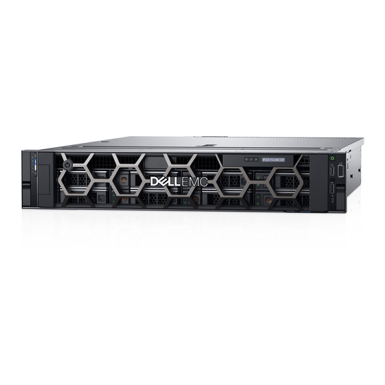
- Page 1 Dell EMC PowerEdge R7515 Installation and Service Manual Regulatory Model: E46S Regulatory Type: E46S003 July 2020 Rev. A03...
- Page 2 Notes, cautions, and warnings NOTE: A NOTE indicates important information that helps you make better use of your product. CAUTION: A CAUTION indicates either potential damage to hardware or loss of data and tells you how to avoid the problem. WARNING: A WARNING indicates a potential for property damage, personal injury, or death.
-
Page 3: Table Of Contents
Contents Chapter 1: About this document....................... 7 Chapter 2: System overview......................8 Front view of the system..............................8 Left control panel view..............................11 Right control panel................................. 12 Rear view of the system..............................13 Inside the system................................. 16 Locating the Express Service Code and Service Tag......................17 System Information label..............................18 Rail sizing and rack compatibility matrix.......................... - Page 4 Drive backplane cover................................. 51 Removing the drive backplane cover...........................51 Installing the drive backplane cover..........................52 Air shroud..................................... 54 Removing the air shroud...............................54 Installing the air shroud..............................55 Cooling fan....................................57 Removing a cooling fan..............................57 Installing a cooling fan..............................58 Intrusion switch module..............................60 Removing the intrusion switch............................
- Page 5 Installing the M.2 SSD module............................108 Optional IDSDM module..............................109 Removing the IDSDM card............................109 Installing IDSDM card..............................110 Micro SD card..................................111 Removing the MicroSD card............................111 Installing the MicroSD card............................112 LOM riser card..................................113 Removing the LOM riser card............................. 113 Installing the LOM riser card............................
- Page 6 Dell Embedded System Diagnostics.......................... 165 Chapter 9: Getting help........................166 Recycling or End-of-Life service information.........................166 Contacting Dell...................................166 Accessing system information by using QRL......................... 166 Quick Resource Locator for PowerEdge R7515 system..................167 Receiving automated support with SupportAssist ....................... 167 Chapter 10: Documentation resources................... 168 Contents...
-
Page 7: Chapter 1: About This Document
About this document This document provides an overview about the system, information about installing and replacing components, technical specifications, diagnostic tools, and guidelines to be followed while installing certain components. About this document... -
Page 8: Chapter 2: System Overview
System overview The PowerEdge R7515 is a 2U rack server that supports: • One AMD EPYC 7002 series processor • 16 DIMM slots • Two redundant power supply units • Up to 8 x 3.5-inch, 12 x 3.5-inch, 12 x 3.5-inch + 2 x 3.5-inch (rear), or 24 x 2.5-inch SAS/SATA or NVMe drives (up to 12 x 2.5-inch SAS/SATA + 12 x 2.5-inch SAS/SATA/ NVMe drives), 8 x 2.5-inch (SAS/SATA/ NVMe ) + 16 NVMe drives or 24 x 2.5-inch NVMe... - Page 9 Table 1. Features available on the front of the system (continued) Item Ports, panels, and slots Icon Description • Status LED: Enables you to identify any failed hardware components. There are up to five status LEDs and an overall system health LED (Chassis health and system ID) bar. For more information, see the Status LED indicators section.
- Page 10 Table 2. Features available on the front of the system (continued) Item Ports, panels, and slots Icon Description management of the system by using mobile devices called as OpenManage Mobile (OMM) feature. Using iDRAC Quick Sync 2 with OpenManage Mobile (OMM) aggregates hardware or firmware inventory and various system level diagnostic and error information that can be used in troubleshooting the system.
-
Page 11: Left Control Panel View
Table 3. Features available on the front of the system (continued) Item Ports, panels, and slots Icon Description Drive (24) Enables you to install drives that are supported on your system. For more information about drives, see the Drives on page 149 section. Right control panel Contains the power button, USB port, iDRAC Direct micro port, and the iDRAC Direct status LED. -
Page 12: Right Control Panel
Table 4. Left control panel (continued) Item Indicator, button, or Icon Description connector based Virtual Machine (KVM), on a supported mobile device. For more information, see the Integrated Dell Remote Access Controller User's Guide at www.dell.com/ poweredgemanuals NOTE: For more information about the indicator codes, see the System diagnostics and indicator codes section. -
Page 13: Rear View Of The System
Rear view of the system Figure 7. Rear view of the system with two rear drives Table 6. Rear view of the system with two rear drives Item Ports, panels, or slots Icon Description Serial port Enables you to connect a serial device to the system. For more information, see the Technical Specifications section. - Page 14 Table 6. Rear view of the system with two rear drives (continued) Item Ports, panels, or slots Icon Description • To locate a particular system within a rack. • To turn the system ID on or off. To reset iDRAC, press and hold the button for 16 seconds. NOTE: •...
- Page 15 Table 7. Rear view of the system with no rear drives (continued) Item Ports, panels, or slots Icon Description Ethernet ports (2) The Ethernet ports that are integrated on the system board provide network connectivity. These NIC ports can also be shared with iDRAC when iDRAC network settings is set to shared mode.
-
Page 16: Inside The System
Inside the system Figure 9. Inside the system 1. Information tag 2. Drive backplane cover 3. Fan (6) 4. Memory module sockets 5. Heat sink 6. Internal PERC mini card and air shroud 7. LOM riser card 8. Air shroud 9. -
Page 17: Locating The Express Service Code And Service Tag
Figure 10. Inside the system with rear drive configuration 1. Information tag 2. Drive backplane cover 3. Fan (6) 4. Memory module sockets 5. Heat sink 6. Internal PERC mini card and air shroud 7. Riser 1A (Low profile right riser) 8. -
Page 18: System Information Label
The Mini Enterprise Service Tag (MEST) label is located on the rear of the system that includes Service Tag (ST), Express Service Code (Exp Svc Code), and Manufacture Date (Mfg. Date). The Exp Svc Code is used by Dell EMC to route support calls to the appropriate personnel. - Page 19 Figure 12. Service information System overview...
- Page 20 Figure 13. Memory Information and icon legend Figure 14. CPU and heat sink and LP right riser System overview...
-
Page 21: Rail Sizing And Rack Compatibility Matrix
Figure 15. Riser Figure 16. System tasks Rail sizing and rack compatibility matrix For specific information about the rail solutions compatible with your system, refer to the Dell EMC Enterprise Systems Rail Sizing and Rack Compatibility Matrix available at https://i.dell.com/sites/csdocuments/Business_solutions_engineering-Docs_Documents/en/rail- rack-matrix.pdf. -
Page 22: Chapter 3: Initial System Setup And Configuration
Initial system setup and configuration This section describes the tasks for initial setup and configuration of the Dell EMC system. The sections provide general steps that you must complete to set up the system and the reference guides for detailed information. -
Page 23: Options To Log In To Idrac
Table 8. Interfaces to set up iDRAC IP address (continued) Interface Documentation links OpenManage Deployment Toolkit OpenManage Deployment Toolkit User's Guide available at https://www.dell.com/openmanagemanuals > Open Manage Deployment Toolkit. Lifecycle Controller Lifecycle Controller User’s Guide at https://www.dell.com/ idracmanuals or for system specific Lifecycle Controller User’s Guide, go to https://www.dell.com/poweredgemanuals >... -
Page 24: Resources To Install Operating System
NOTE: For more information about Installation and How-to videos for supported operating systems on PowerEdge system see, Supported Operating Systems for Dell EMC PowerEdge systems. Options to download firmware You can download firmware from Dell support site. For information, see the Downloading drivers and firmware section. -
Page 25: Downloading Drivers And Firmware
Steps 1. Go to www.dell.com/support/drivers. 2. Enter the Service Tag of the system in the Enter a Dell Service Tag, Dell EMC Product ID or Model field, and then press Enter. NOTE: If you do not have the Service Tag, select Detect PC to automatically detect the Service Tag, or click Browse all products, and navigate to your product. -
Page 26: Chapter 4: Pre-Operating System Management Applications
Pre-operating system management applications You can manage basic settings and features of a system without booting to the operating system by using the system firmware. Options to manage the pre-operating system applications You can use any one of the following options to manage the pre-operating system applications: •... -
Page 27: System Bios
System BIOS To view the System BIOS screen, power on the system, press F2, and click System Setup Main Menu > System BIOS. Table 13. System BIOS details Option Description System Information Provides information about the system such as the system model name, BIOS version, and Service Tag. - Page 28 Table 14. System Information details (continued) Option Description UEFI Compliance Version Specifies the UEFI compliance level of the system firmware. AGESA Version Specifies the AGESA reference code version. SMU Version Specifies the SMU firmware version. DXIO Version Specifies the DXIO firmware version. Memory Settings To view the Memory Settings screen, power on the system, press F2, and click System Setup Main Menu >...
- Page 29 Table 16. Processor Settings details (continued) Option Description L1 Stream HW Prefetcher Enables or disables the L1 stream hardware prefetcher. This option is set to Enabled by default. L2 Stream HW Prefetcher Enables or disables the L2 stream hardware prefetcher. This option is set to Enabled by default.
- Page 30 Table 18. SATA Settings details (continued) Option Description 1. You might also need to change the Boot Mode setting to UEFI. Otherwise, you should set the field to Non-RAID mode. 2. No ESXi and Ubuntu OS support under RAID mode. Security Freeze Lock Sends Security Freeze Lock command to the embedded SATA drives during POST.
- Page 31 Table 20. Boot Settings details (continued) Option Description Boot Sequence Retry Enables or disables the Boot Sequence Retry feature. If this option is set to Enabled and the system fails to boot, the system re-attempts the boot sequence after 30 seconds. This option is set to Enabled by default.
- Page 32 Network Settings To view the Network Settings screen, power on the system, press F2, and click System Setup Main Menu > System BIOS > Network Settings. Linux Network Tuning Guide for AMD EPYC NOTE: For information about Linux network performance settings, see the Processor Based Servers at AMD.com.
- Page 33 Table 24. HTTP Device n Settings details (continued) Option Description Secondary DNS Specifies the secondary DNS server IP address for the HTTP Device. Obtain URI from the DHCP server if not specified Table 25. UEFI iSCSI Settings screen details Option Description iSCSI Initiator Name Specifies the name of the iSCSI initiator in IQN format.
- Page 34 Table 27. Integrated Devices details (continued) Option Description Embedded Video Controller Enables or disables the use of Embedded Video Controller as the primary display. When set to Enabled, the Embedded Video Controller will be the primary display even if add-in graphic cards are installed. When set to Disabled, an add-in graphics card will be used as the primary display.
- Page 35 Table 27. Integrated Devices details (continued) Option Description The default is set to Platform Default Bifurcation. The slot bifurcation field is accessible when set to Manual bifurcation Control and is grayed out when set to Platform Default Bifurcation. Serial Communication To view the Serial Communication screen, power on the system, press F2, and click System Setup Main Menu >...
- Page 36 Table 29. System Profile Settings details Option Description System Profile Sets the system profile. If you set the System Profile option to a mode other than Custom, the BIOS automatically sets the rest of the options. You can only change the rest of the options if the mode is set to Custom.
- Page 37 Table 31. TPM 1.2 security information Option Description TPM Security NOTE: The TPM menu is available only when the TPM module is installed. Enables you to control the reporting mode of the TPM. The TPM Security option is set to Off by default. You can only modify the TPM Status, and TPM Activation if the TPM Status field is set to either On with Pre-boot Measurements or On without Pre-boot Measurements.
- Page 38 Table 33. System Security details (continued) Option Description Secure Boot Mode Configures how the BIOS uses the Secure Boot Policy Objects (PK, KEK, db, dbx). If the current mode is set to Deployed Mode, the available options are User Mode and Deployed Mode.
- Page 39 A message prompts you to save the changes. NOTE: Password protection does not take effect until the system reboots. Using your system password to secure your system About this task If you have assigned a setup password, the system accepts your setup password as an alternate system password. Steps 1.
- Page 40 • You cannot disable or change an existing system password. NOTE: You can use the password status option with the setup password option to protect the system password from unauthorized changes. Redundant OS Control To view the Redundant OS Control screen, power on the system, press F2, and click System Setup Main Menu > System BIOS > Redundant OS Control.
-
Page 41: Idrac Settings Utility
Table 36. Miscellaneous Settings details (continued) Option Description Power Cycle Request Enables or disables the Power Cycle Request. This option is set to None by default. iDRAC Settings utility The iDRAC settings utility is an interface to set up and configure the iDRAC parameters by using UEFI. You can enable or disable various iDRAC parameters by using the iDRAC settings utility. -
Page 42: Pxe Boot
PXE boot You can use the Preboot Execution Environment (PXE) option to boot and configure the networked systems remotely. To access the PXE boot option, boot the system and then press F12 during POST instead of using standard Boot Sequence from BIOS Setup. -
Page 43: Chapter 5: Installing And Removing System Components
Installing and removing system components Topics: • Safety instructions • Before working inside your system • After working inside your system • Recommended tools • Cable routing • Optional front bezel • System cover • Drive backplane cover • Air shroud •... -
Page 44: Before Working Inside Your System
NOTE: While replacing the hot swappable PSU, after next server boot; the new PSU automatically updates to the same firmware and configuration of the replaced one. For more information about the Part replacement configuration, see the Lifecycle Controller User's Guide at https://www.dell.com/idracmanuals NOTE: While replacing faulty storage controller/FC/NIC card with the same type of card, after you power on the... -
Page 45: Cable Routing
Cable routing Figure 17. Cable routing - 8 x 3.5 inch drive backplane with ODD Figure 18. Cable routing - 8 x 3.5 inch drive backplane with mini PERC card Installing and removing system components... - Page 46 Figure 19. Cable routing - 12 x 3.5 inch drive backplane with 2 x 3.5 inch rear drive backplane Figure 20. Cable routing - 12 x 2.5 inch SAS drive + 12 x 2.5 inch NVMe drive backplane Installing and removing system components...
-
Page 47: Optional Front Bezel
Figure 21. Cable routing - 24 x 2.5 inch NVMe drive backplane Optional front bezel NOTE: LCD panel is optional on the front bezel. If the front bezel has an LCD panel, see LCD panel section. Removing the front bezel Prerequisites 1. -
Page 48: Installing The Front Bezel
Figure 22. Removing the front bezel Installing the front bezel Prerequisites 1. Follow the safety guidelines listed in the Safety instructions on page 43. NOTE: The bezel key is part of the bezel package. Steps 1. Align and insert the tabs on the bezel into the slots on the chassis. 2. -
Page 49: System Cover
Figure 23. Installing the front bezel System cover Removing the system cover Prerequisites 1. Follow the safety guidelines listed in the Safety instructions on page 43. 2. Follow the procedure listed in the Before working inside your system on page 44. 3. -
Page 50: Installing The System Cover
Figure 24. Removing the system cover Next steps Replace the system cover. Installing the system cover Prerequisites 1. Follow the safety guidelines listed in the Safety instructions on page 43. 2. Follow the procedure listed in the Before working inside your system on page 44. -
Page 51: Drive Backplane Cover
Figure 25. Installing the system cover Next steps Follow the procedure listed in After working inside your system on page 44. Drive backplane cover Removing the drive backplane cover Prerequisites 1. Follow the safety guidelines listed in the Safety instructions on page 43. -
Page 52: Installing The Drive Backplane Cover
Figure 26. Removing the drive backplane cover Next steps Install the drive backplane. Installing the drive backplane cover Prerequisites 1. Follow the safety guidelines listed in the Safety instructions on page 43. 2. Follow the procedure listed in the Before working inside your system on page 44. - Page 53 Figure 27. Installing the drive backplane cover Next steps 1. Follow the procedure listed in After working inside your system on page 44. Installing and removing system components...
-
Page 54: Air Shroud
Air shroud Removing the air shroud Prerequisites 1. Follow the safety guidelines listed in the Safety instructions on page 43. 2. Follow the procedure listed in the Before working inside your system on page 44. CAUTION: Never operate your system with the air shroud removed. The system may get overheated quickly, resulting in shutdown of the system and loss of data. -
Page 55: Installing The Air Shroud
Figure 29. Removing the air shroud for system with rear drives Next steps Replace the air shroud. Installing the air shroud Prerequisites 1. Follow the safety guidelines listed in the Safety instructions on page 43. 2. Follow the procedure listed in the Before working inside your system on page 44. - Page 56 Figure 30. Installing the air shroud Figure 31. Installing the air shroud for system with rear drives Next steps 1. Follow the procedure listed in After working inside your system on page 44. Installing and removing system components...
-
Page 57: Cooling Fan
Cooling fan Removing a cooling fan Prerequisites 1. Follow the safety guidelines listed in the Safety instructions on page 43. 2. Follow the procedure listed in the Before working inside your system on page 44. Remove the air shroud. Steps 1. -
Page 58: Installing A Cooling Fan
Figure 33. Disconnecting fan 1 cable from PIB Next steps Replace the cooling fan. Installing a cooling fan Prerequisites 1. Follow the safety guidelines listed in the Safety instructions on page 43. 2. Follow the procedure listed in the Before working inside your system on page 44. - Page 59 Figure 34. Installing a fan 3. Connect the cooling fan cable (2, 3, 4, 5, and 6) to the connector on system board. NOTE: Ensure to connect the cooling fan 1 cable from the connector on the power interposer board. Figure 35.
-
Page 60: Intrusion Switch Module
Next steps Install the air shroud. 2. Follow the procedure listed in After working inside your system on page 44. Intrusion switch module Removing the intrusion switch Prerequisites 1. Follow the safety guidelines listed in the Safety instructions on page 43. 2. -
Page 61: Drives
2. Follow the procedure listed in the Before working inside your system on page 44. Remove the air shroud. Steps 1. Align and insert the intrusion switch in the slot until it is firmly seated in the slot on the chassis. NOTE: Route the cable properly when you replace it to prevent the cable from being pinched or crimped. -
Page 62: Installing The Drive Blank
Figure 38. Removing a drive blank Next steps Install a drive or replace the drive blank. Installing the drive blank Prerequisites 1. Follow the safety guidelines listed in the Safety instructions on page 43. 2. If installed, remove the front bezel. -
Page 63: Installing The Drive Carrier
CAUTION: Before attempting to remove or install a drive while the system is running, see the documentation for the storage controller card to ensure that the host adapter is configured correctly to support drive removal and insertion. CAUTION: To prevent data loss, ensure that your operating system supports drive installation. See the documentation supplied with your operating system. -
Page 64: Removing The Drive From The Drive Carrier
NOTE: Ensure that the drive carrier's release handle is in the open position before inserting the carrier into the slot. 1. Follow the safety guidelines listed in the Safety instructions on page 43. 2. If installed, remove the front bezel. Remove the drive carrier or drive blank when you want to assemble the drives in to the system. -
Page 65: Installing The Drive Into The Drive Carrier
Figure 42. Removing the drive from the drive carrier Next steps Install the drive into the drive carrier. Installing the drive into the drive carrier Prerequisites 1. Follow the safety guidelines listed in the Safety instructions on page 43. 2. If installed, remove the front bezel. -
Page 66: Drive Backplane
Drive backplane Drive backplane Depending on your system configuration, the drive backplanes supported in PowerEdge R7515 are listed here: • 3.5 inch (x8) SAS, SATA backplane • 3.5 inch (x12) SAS or SATA backplane and 3.5 inch (x2) SAS or SATA backplane (rear) •... - Page 67 3. SAS/SATA A cable connector 4. Power connector Figure 45. 12 X 3.5 inch drive backplane 1. Power cable connector 2. SAS/SATA cable connector 3. SAS/SATA cable connector 4. Backplane signal connector 5. SAS cable connector Figure 46. 2 x 3.5 inch drive backplane (rear) 1.
-
Page 68: Removing The Drive Backplane
11. Signal cable (B0) connector Figure 48. 24 x 2.5 inch NVMe drive backplane 1. Expander board connector B1 (PE1_B) 2. Expander board connector A1 (PE1_A) 3. Expander board connector B2 (PE2_B) 4. Expander board connector A2 (PE2_A) 5. signal connector (J_SIG_A1) 6. -
Page 69: Installing The Drive Backplane
Figure 49. Removing the drive backplane 3. Disconnect the following cables from the backplane: a. Backplane signal cable b. Backplane power cable c. If applicable, PERC cable Next steps Replace the drive backplane. Installing the drive backplane Prerequisites 1. Follow the safety guidelines listed in the Safety instructions on page 43. -
Page 70: Removing The Rear Drive Backplane
3. Lower the backplane until the blue release tabs click into place. Figure 50. Installing the drive backplane Next steps Install the drives in their original locations. Install the drive backplane cover. 3. Follow the procedure listed in After working inside your system on page 44. -
Page 71: Installing The Rear Drive Backplane
Figure 51. Removing the rear drive backplane Next steps Install the rear drive backplane. Installing the rear drive backplane Prerequisites 1. Follow the safety guidelines listed in the Safety instructions on page 43. 2. Follow the procedure listed in the Before working inside your system on page 44. -
Page 72: Rear Drive Cage
Figure 52. Installing the rear drive backplane Next steps Install the rear drive cage. 2. Connect all the cables to the backplane. Install the drives in their original location. 4. Follow the procedure listed in After working inside your system on page 44. -
Page 73: Installing The Rear Drive Cage
Figure 53. Removing the rear drive cage Next steps Replace the rear drive cage. Installing the rear drive cage Prerequisites 1. Follow the safety guidelines listed in the Safety instructions on page 43. 2. Follow the procedure listed in the Before working inside your system on page 44. -
Page 74: System Memory
System memory System memory guidelines The PowerEdge R7515 system supports DDR4 registered DIMMs (RDIMMs) and load reduced DIMMs (LRDIMMs). System memory holds the instructions that are executed by the processor. Your system memory is organized into eight channels per processor (two memory sockets per channel) for a total of 16 memory sockets per processor. -
Page 75: General Memory Module Installation Guidelines
Table 39. Supported memory matrix (continued) DIMM Rank Capacity DIMM rated voltage and Operating Speed type speed RDIMM 8 GB DDR4 (1.2V), 3200 MT/s 3200 MT/s 2933 MT/s 16 GB, 32 GB, 64 GB DDR4 (1.2V), 3200 MT/s 3200 MT/s 2933 MT/s LRDIMM 128 GB... - Page 76 • The BIOS Setup menu presents the applicable NPSx options based on the underlying model number. A change to the current NPSx is communicated to pre-BIOS firmware to take effect on the next boot. The default NPS setting is 1. •...
- Page 77 Table 42. Optimal NPS configuration Number of DIMMs per processor • Recommended NPS setting is marked by X that indicate optimal performance. • NPS0 is only available for dual processor systems and is the preferred setting. • The NPS setting that are blank are functional. However, indicate non-optimal performance. •...
-
Page 78: Removing A Memory Module
Removing a memory module Prerequisites 1. Follow the safety guidelines listed in the Safety instructions on page 43. 2. Follow the procedure listed in the Before working inside your system on page 44. Remove the air shroud. NOTE: The memory modules are hot to touch for some time after the system has been powered down. Allow the memory modules to cool before handling them. - Page 79 NOTE: Ensure the socket ejector latches are fully open, before installing the memory module. 3. Align the edge connector of the memory module with the alignment key of the memory module socket, and insert the memory module in the socket. CAUTION: To prevent damage to the memory module or the memory module socket during installation, do not bend or flex the memory module;...
-
Page 80: Processor And Heat Sink
Processor and heat sink Removing the heat sink Prerequisites 1. Follow the safety guidelines listed in the Safety instructions on page 43. 2. Follow the procedure listed in the Before working inside your system on page 44. Remove the air shroud. -
Page 81: Removing The Processor
Removing the processor Prerequisites CAUTION: The heat sink may be hot to touch for some time after the system has been powered off. Allow the heat sink to cool before removing it. 1. Follow the safety guidelines listed in the Safety instructions on page 43. - Page 82 Figure 59. Lifting the rail frame 3. Holding the blue tab on the processor tray, slide the tray out of the rail frame. Figure 60. Removing the processor tray Next steps Replace the processor. Installing and removing system components...
-
Page 83: Installing The Processor
Installing the processor Prerequisites 1. Follow the safety guidelines listed in the Safety instructions on page 43. 2. Follow the procedure listed in Before working inside your system on page 44. Remove the air shroud. Remove the heat sink. 5. If the processor has previously been used in a system, remove any remaining thermal grease from the processor by using a lint-free cloth. - Page 84 Figure 62. Closing the rail frame 3. Secure the force plate to the processor socket base by tightening the screws in the sequence 1, 2, and 3. When all three screws are fully threaded, the socket is then actuated. The three screws are tightened to a torque value of 12.0 ± 1.0 lbf-in. NOTE: Press the force plate while tightening the screws to avoid tilting of the processor cover out of the processor socket.
-
Page 85: Installing The Heat Sink
Install the air shroud. 3. Follow the procedure listed in After working inside your system on page 44. Installing the heat sink Prerequisites 1. Follow the safety guidelines listed in the Safety instructions on page 43. 2. Follow the procedure listed in the Before working inside your system on page 44. -
Page 86: Expansion Cards And Expansion Card Risers
A system event entry is logged in the iDRAC Lifecycle Controller if an expansion card riser is not supported or missing. It does not prevent your system from turning on. However, if a F1/F2 pause occurs with an error message, see Troubleshooting expansion cards section in the Dell EMC PowerEdge Servers Troubleshooting Guide at www.dell.com/ poweredgemanuals. - Page 87 The following table provides guidelines for installing expansion cards to ensure proper cooling and mechanical fit. The expansion cards with the highest priority should be installed first using the slot priority indicated. All the other expansion cards should be installed in the card priority and slot priority order.
- Page 88 Table 45. Riser configurations: Riser 1A + Riser 2 – CPU (continued) Card type Slot priority Maximum number of cards LOM riser ; 2x10G BCM57416 (BASeT/SFP LOM riser ; 2x25G (Broadcom) NVMe PCIe SSD 2, 3 Mellanox 100G (CX5/CX6 H100) 3, 2 Mellanox 25G (CX4LX DP/CX5 DP) 2, 3...
- Page 89 Table 46. Riser configurations: Riser 1B – CPU (continued) Card type Slot priority Maximum number of cards Intel 10G (BaseT DP LP) 5, 4 Intel 10G (SFP+ DP FH) 2, 3 Intel 10G (SFP+ DP LP) 5, 4 Intel 1G (QP FH) 2, 3 Intel 1G (QP LP) 5, 4...
-
Page 90: Removing The Expansion Card Riser
Table 46. Riser configurations: Riser 1B – CPU (continued) Card type Slot priority Maximum number of cards PERC 10 : External adapter (H840, LP) 5, 4 HBA : External adapter (LP) 5, 4 Internal storage (BOSS, LP) 5, 4 PERC 9 : Mini mono (H730P/H330) Integrated slot PERC 10 : Mini mono (H740P) Integrated slot... - Page 91 Figure 67. Removing the riser 1A b. For the riser 1B, Using a Phillips #2 screwdriver, loosen the captive screws securing the riser to the system board and the chassis. ii. Holding the touch points, lift the riser from the system. Figure 68.
-
Page 92: Installing The Expansion Card Riser
Next steps Replace the expansion card riser. Installing the expansion card riser Prerequisites 1. Follow the safety guidelines listed in the Safety instructions on page 43. 2. Follow the procedure listed in the Before working inside your system on page 44. Remove the air shroud. - Page 93 Figure 70. Installing the riser 1A b. For the riser 1B, tighten the captive screws of the riser to fit the riser firmly to the system board and the chassis. Figure 71. Installing the riser 1B Installing and removing system components...
-
Page 94: Removing An Expansion Card
Next steps Install the rear drive cage. Install the air shroud. 3. Follow the procedure listed in After working inside your system on page 44. Removing an expansion card Prerequisites 1. Follow the safety guidelines listed in the Safety instructions on page 43. -
Page 95: Installing An Expansion Card
Figure 73. Installing the filler bracket NOTE: Filler brackets must be installed over empty expansion card slots to maintain FCC certification of the system. The brackets also keep dust and dirt out of the system and aid in proper cooling and airflow inside the system. Next steps Install an expansion card. - Page 96 Figure 74. Removing the filler bracket NOTE: Store the filler bracket for future use. Filler brackets must be installed in empty expansion card slots to maintain FCC certification of the system. The brackets also keep dust and dirt out of the system and aid in proper cooling and airflow inside the system.
-
Page 97: Removing An Expansion Card From The Expansion Card Riser
Figure 75. Installing an expansion card on the system board Next steps 1. Connect the required cables to the expansion card. 2. If removed, install the rear drive cage. Install the air shroud. 4. Follow the procedure listed in After working inside your system on page 44. - Page 98 Figure 76. Removing the expansion card from riser 1B Figure 77. Removing the expansion card from riser 1A Installing and removing system components...
- Page 99 Figure 78. Removing the expansion card from riser 2 3. Install a filler bracket if you are not replacing the expansion card. NOTE: You must install a filler bracket over an empty expansion card slot to maintain Federal Communications Commission (FCC) certification of the system. The brackets also keep dust and dirt out of the system and aid in proper cooling and airflow inside the system.
-
Page 100: Installing An Expansion Card Into The Expansion Card Riser
Figure 80. Installing a filler bracket for riser 1A Figure 81. Installing a filler bracket for riser 2 Next steps Install the expansion card into the expansion card riser. Installing an expansion card into the expansion card riser Prerequisites 1. Follow the safety guidelines listed in the Safety instructions on page 43. - Page 101 NOTE: The procedure to install expansion card into the riser 1A, riser 2, or riser 1B is identical. Steps 1. Pull and lift to open the expansion card retention latch lock. 2. If installed, remove the filler bracket. NOTE: Store the filler bracket for future use. Filler brackets must be installed in empty expansion card slots to maintain Federal Communications Commission (FCC) certification of the system.
- Page 102 Figure 84. Removing a filler bracket for a riser 2 3. Holding the card by its edges, align the card and insert the expansion card in the connector on the expansion card riser. 4. Close the expansion card retention latch. Figure 85.
-
Page 103: Removing An Accelerator Card
Figure 86. Installing the expansion card into a riser 1A Figure 87. Installing the expansion card into a riser 2 Next steps Install the expansion card riser. Install the air shroud. 3. Follow the procedure listed in After working inside your system on page 44. - Page 104 NOTE: The procedure to remove expansion card from riser 1A, riser 2, or riser 1B is identical. Steps 1. Disconnect the FPGA cable from the Power Interposer Board (PIB) and expansion card riser. Figure 88. Disconnecting the FPGA cable from the PIB and the expansion card riser 2.
-
Page 105: Installing An Accelerator Card
Figure 90. Removing the accelerator card from riser 1B 4. Install a filler bracket if you are not replacing the expansion card. For information about how to install a filler bracket, see installing a filler bracket section in the Removing the expansion card topic. - Page 106 Figure 91. Installing the accelerator card into riser 1B 4. Ensure to close the latch for the accelerator card. Figure 92. Closing the latch on the expansion card riser 5. Connect the FPGA cable to the PIB and the expansion card riser. NOTE: The V100S GPU power cable is different from the FPGA cable.
-
Page 107: M.2 Ssd Module
Figure 93. Connecting the FPGA cable for the accelerator card Next steps Install the air shroud. 2. Follow the procedure listed in After working inside your system on page 44. M.2 SSD module Removing the M.2 SSD module Prerequisites 1. Follow the safety guidelines listed in the Safety instructions on page 43. -
Page 108: Installing The M.2 Ssd Module
Figure 94. Removing the M.2 SSD module Next steps Replace the M.2 SSD module. Installing the M.2 SSD module Prerequisites 1. Follow the safety guidelines listed in the Safety instructions on page 43. 2. Follow the procedure listed in the Before working inside your system on page 44. -
Page 109: Optional Idsdm Module
Figure 95. Installing the M.2 SSD module Next steps Install the BOSS card into the riser. NOTE: The procedure to install the BOSS card is similar to removing an expansion card. Install expansion card riser Install the air shroud. 4. Follow the procedure listed in After working inside your system on page 44. -
Page 110: Installing Idsdm Card
Figure 96. Removing the IDSDM card Next steps NOTE: If you are replacing the IDSDM module, remove the MicroSD cards. Replace the IDSDM module. Installing IDSDM card Prerequisites 1. Follow the safety guidelines listed in the Safety instructions on page 43. 2. -
Page 111: Micro Sd Card
Figure 97. Installing IDSDM card Next steps Install the MicroSD cards. NOTE: Reinstall the MicroSD cards into the same slots that are based on the labels you had marked on the cards during removal. Install the air shroud. 3. Follow the procedure listed in After working inside your system on page 44. -
Page 112: Installing The Microsd Card
Figure 98. Removing the MicroSD card Next steps Replace the MicroSD cards. Installing the MicroSD card Prerequisites 1. Follow the safety guidelines listed in the Safety instructions on page 43. 2. Follow the procedure listed in the Before working inside your system on page 44. -
Page 113: Lom Riser Card
Figure 99. Installing the MicroSD card Next steps Install the IDSDM module. 2. Follow the procedure listed in After working inside your system on page 44. LOM riser card Removing the LOM riser card Prerequisites 1. Follow the safety guidelines listed in the Safety instructions on page 43. - Page 114 Figure 100. Removing the LOM riser card 5. Lift the LOM riser card out of the system. 6. Remove the LOM riser bracket. a. Using a Phillips #2 screwdriver, remove the screw that secures the bracket to the chassis. b. Slide the bracket out of the slot on the chassis. Figure 101.
-
Page 115: Installing The Lom Riser Card
b. Using a Phillips #2 screwdriver, secure the LOM filler bracket to the chassis with a screw Figure 102. Installing the LOM filler bracket Next steps Replace the LOM riser card. Installing the LOM riser card Prerequisites 1. Follow the safety guidelines listed in the Safety instructions on page 43. - Page 116 Figure 103. Removing the LOM filler bracket 2. Install the LOM riser bracket. a. Insert and slide the LOM riser bracket into the slot on the chassis. b. Using a Phillips #2 screwdriver, secure the bracket to the chassis with a screw. Figure 104.
-
Page 117: Storage Controller Card
Figure 105. Installing the LOM riser card Next steps Replace the expansion card riser. 2. If removed, replace the rear drive cage. Install the air shroud. 4. Follow the procedure listed in After working inside your system on page 44. Storage controller card Removing the mini PERC card air shroud Prerequisites... -
Page 118: Installing The Mini Perc Card Air Shroud
Steps 1. Remove the screw securing the mini PERC card air shroud to the system board. Figure 106. Removing the mini PERC card air shroud 2. Remove the air shroud from the system. Next steps Replace the PERC card air shroud. -
Page 119: Removing The Internal Mini Perc Card
Figure 107. Installing the mini PERC card air shroud Next steps 1. If removed, replace the expansion card riser. 2. If removed, replace the rear drive cage. Install the air shroud. 4. Follow the procedure listed in After working inside your system on page 44. -
Page 120: Installing The Internal Mini Perc Card
Figure 108. Removing the Internal mini PERC card Next steps Replace the internal mini PERC card. Installing the Internal mini PERC card Prerequisites 1. Follow the safety guidelines listed in the Safety instructions on page 43. 2. Follow the procedure listed in the Before working inside your system on page 44. -
Page 121: System Battery
Figure 109. Installing the PERC card Next steps Install the air shroud. 2. If removed, replace the expansion card riser. 3. If removed, replace the rear drive cage. Install the PERC card air shroud. 5. Follow the procedure listed in After working inside your system on page 44. - Page 122 Figure 110. Removing the system battery 2. To install a system battery, press the battery into the connector until it snaps into place. 3. Insert the battery in the battery holder until the battery holder clip snaps into place. Figure 111. Installing the system battery Next steps Install the air shroud.
-
Page 123: Optional Internal Usb Memory Key
f. Enter the System Setup and if the time and date are still incorrect, see Getting help section. Optional internal USB memory key NOTE: To locate the internal USB port on the system board, see the System board jumpers and connectors section. -
Page 124: Optional Optical Drive
Figure 113. Installing the internal USB memory key a. USB memory key b. USB port Next steps Install the air shroud. 2. Follow the procedure listed in After working inside your system on page 44. 3. While booting, press F2 to enter System Setup and verify that the system detects the USB memory key. Optional optical drive Removing the optical drive The procedure for removing an optical drive and optical drive blank is the same. - Page 125 Figure 114. Removing optical drive 3. If you are not installing a new optical drive, install the optical drive blank. The procedure to install the optical drive blank is the same as the optical drive. Figure 115. Installing optical drive blank Next steps Replace the optical drive.
-
Page 126: Installing The Optional Optical Drive
Installing the optional optical drive The procedure for installing an optical drive and optical drive blank. Prerequisites 1. Follow the safety guidelines listed in the Safety instructions on page 43. 2. Follow the procedure listed in the Before working inside your system on page 44. -
Page 127: Power Supply Unit
Figure 117. Installing optical drive Next steps 1. Connect the power and data cables to the connector on the optical drive and the connector on the system board. NOTE: Route the cable properly on the side of the system to prevent it from being pinched or crimped. 2. -
Page 128: Removing A Power Supply Unit Blank
Removing a power supply unit blank Prerequisites 1. Follow the safety guidelines listed in the Safety instructions on page 43. Steps Pull the blank out of the system. CAUTION: To ensure proper system cooling, the power supply unit blank must be installed in the second power supply unit bay in a non-redundant configuration. -
Page 129: Installing A Power Supply Unit
Figure 119. Removing a power supply unit Next steps Replace the power supply units Install the PSU blank. Installing a power supply unit Prerequisites 1. Follow the safety guidelines listed in the Safety instructions on page 43. 2. For systems that support redundant PSU, ensure that both the PSUs are of the same type and have the same maximum output power. -
Page 130: Installing A Power Supply Unit Blank
Figure 120. Installing a power supply unit Next steps 1. If you have unlatched the cable management arm, relatch it. For information about the cable management arm, see the system’s rack documentation at www.dell.com/poweredgemanuals. 2. Connect the power cable to the PSU, and plug the cable into a power outlet. NOTE: When connecting the power cable to the PSU, secure the cable to the PSU with the strap. -
Page 131: Power Interposer Board
Figure 121. Installing a power supply unit blank Power interposer board Removing the power interposer board Prerequisites 1. Follow the safety guidelines listed in the Safety instructions on page 43. 2. Follow the procedure listed in the Before working inside your system on page 44. -
Page 132: Installing The Power Interposer Board
Figure 122. Removing the power interposer board Next steps Replace the power interposer board. Installing the power interposer board Prerequisites 1. Follow the safety guidelines listed in the Safety instructions on page 43. 2. Follow the procedure listed in the Before working inside your system on page 44. -
Page 133: System Board
Figure 123. Installing the power interposer board Next steps Install the air shroud. Install the power supply units. 3. Follow the procedure listed in After working inside your system on page 44. System board Removing the system board Prerequisites CAUTION: If you are using the Trusted Platform Module (TPM) with an encryption key, you may be prompted to create a recovery key during program or System Setup. -
Page 134: Installing The System Board
LOM riser card k. If applicable, rear drive cage Trusted Platform Module m. Disconnect the fan cables CAUTION: To prevent damage to the processor socket when replacing a faulty system board, ensure that you cover the processor socket with the processor dust cover. o. - Page 135 Steps 1. Unpack the new system board assembly. NOTE: Do not lift the system board by holding a memory module, processor, or other components. CAUTION: Take care not to damage the system identification button while placing the system board into the chassis. 2.
-
Page 136: Restoring The System Using Easy Restore
NOTE: Ensure that the cables inside the system are routed along the chassis wall and secured using the cable securing bracket. 2. Follow the procedure listed in After working inside your system on page 44. 3. Power on the system. 4. -
Page 137: Trusted Platform Module
Trusted Platform Module Upgrading the Trusted Platform Module Prerequisites NOTE: • Ensure that your operating system supports the version of the TPM module being installed. • Ensure that you download and install the latest BIOS firmware on your system. • Ensure that the BIOS is configured to enable UEFI boot mode. -
Page 138: Initializing Tpm For Users
Initializing TPM for users Steps 1. Initialize the TPM. For more information, see Initializing the TPM for users. 2. The TPM Status changes to Enabled, Activated. Initializing the TPM 1.2 for users Steps 1. While booting your system, press F2 to enter System Setup. 2. -
Page 139: Installing The Left Control Panel
Figure 127. Removing the left control panel Next steps Replace the left control panel. Installing the left control panel Prerequisites 1. Follow the safety guidelines listed in the Safety instructions on page 43. 2. Follow the procedure listed in the Before working inside your system on page 44. -
Page 140: Removing The Right Control Panel
Figure 128. Installing the left control panel Next steps Install the air shroud. 2. Follow the procedure listed in After working inside your system on page 44. Removing the right control panel Prerequisites 1. Follow the safety guidelines listed in the Safety instructions on page 43. -
Page 141: Installing The Right Control Panel
Figure 129. Removing the right control panel Next steps Replace the right control panel. Installing the right control panel Prerequisites 1. Follow the safety guidelines listed in the Safety instructions on page 43. 2. Follow the procedure listed in the Before working inside your system on page 44. - Page 142 Figure 130. Installing the right control panel 5. Connect the VGA cable to the connector on the system board and close the blue cable retention latch. Next steps Replace the air shroud. 2. Follow the procedure listed in After working inside your system on page 44.
-
Page 143: Chapter 6: Jumpers And Connectors
Jumpers and connectors This topic provides some basic and specific information about jumpers and switches. It also describes the connectors on the various boardsboard in the system. Jumpers on the system board help to disable the system and reset the passwords. To install components and cables correctly, you must know the connectors on the system board. -
Page 144: System Board Jumper Settings
3. PWRD_EN (Jumpers) 4. NVRAM_CLR (Jumpers) 5. LOM riser card 6. Battery 7. Riser slot 1A/Riser slot 1B 8. Mini PERC 9. System power 3 10. DIMMS for processor 11. Fan 6 12. Fan 5 13. SATA_A/PCIE_A 14. Fan 4 15. - Page 145 NOTE: The existing passwords are not disabled (erased) until the system boots with the jumper on pins 4 and 6. However, before you assign a new system and/or setup password, you must move the jumper back to pins 2 and 4. NOTE: If you assign a new system and/or setup password with the jumper on pins 4 and 6, the system disables the new password(s) the next time it boots.
-
Page 146: Chapter 7: Technical Specifications
System battery specifications • Expansion card riser specifications • Memory specifications • Storage controller specifications • Drive specifications • Ports and connectors specifications • Video specifications • Environmental specifications System dimensions Figure 132. Dimensions of the PowerEdge R7515 system Technical specifications... -
Page 147: Chassis Weight
Table 50. PowerEdge R7515 processor specifications Supported processor Number of processors supported AMD EPYC 7002 series processor PSU specifications The PowerEdge R7515 system supports the following AC or DC power supply units (PSU): Table 51. PSU specifications Class Heat dissipation Frequency... -
Page 148: Supported Operating Systems
For more information, see www.dell.com/ossupport. Cooling fans specifications The PowerEdge R7515 system supports both the Standard fan (STD fan) and High Performance fan (HPR fan) and requires all six fans to be installed. NOTE: Mixing of STD and HPR fans is not supported. -
Page 149: Memory Specifications
Memory specifications The PowerEdge R7515 system supports the following memory specifications for optimized operation. Table 53. Memory specifications DIMM type DIMM rank DIMM capacity Minimum RAM Maximum RAM Single rank 8 GB 8 GB 128 GB 16 GB 16 GB... -
Page 150: Optical Drives
The micro USB 2.0 compliant port can only be used as an iDRAC Direct or a management port. LOM Riser card specifications The PowerEdge R7515 system supports up to two 10/100/1000 Mbps Network Interface Controller (NIC) ports that are located on the back panel. The system also supports LAN on Motherboard (LOM) on an optional riser card. -
Page 151: Serial Connector Specifications
9-pin connector, Data Terminal Equipment (DTE), 16550-compliant. VGA ports specifications The Video Graphic Array (VGA) port enables you to connect the system to a VGA display. The PowerEdge R7515 system supports two 15-pin VGA ports one each on the front and back panels. -
Page 152: Environmental Specifications
Table 59. Supported rear video resolution options (continued) Resolution Refresh rate (Hz) Color depth (bits) 1920 x 1080 8, 16, 32 1920 x 1200 8, 16, 32 Environmental specifications The following sections contain information about the environmental specifications of the system. NOTE: For additional information about environmental certifications, please refer to the Product Environmental Datasheet located with the Manuals &... -
Page 153: Thermal Restriction Matrix
Thermal restriction for ASHRAE A4/Fresh air environment (UI) • Two PSUs are required in redundant mode. Single PSU failure is not supported • LRDIMM is not supported. • Processor TDP equal or greater than 155 W are not supported. • 128 GB or greater capacity DIMMs are not supported. - Page 154 Table 65. Label references (continued) Label references Full Height (Riser) Double Wide (Xilinx FPGA accelerator) Table 66. Thermal restriction matrix Drive Configuration type 8 x 3.5- 12 x 3.5- 12 x 3.5- 24 x 2.5-inch drives 12 x 2.5-inch drives 24 x 2.5-inch drives inch inch...
- Page 155 Table 67. Thermal restriction matrix for T4 GPU Card Drive Configuration type 8 x 3.5-inch 12 x 3.5-inch 12 x 3.5-inch 24 x 2.5-inch 12 x 2.5-inch 24 x 2.5-inch drives drives drives drives drives SAS + drives NVMe 12 x 2.5-inch drives NVMe Rear Configuration 2LP+2FH...
-
Page 156: Particulate And Gaseous Contamination Specifications
Table 68. Thermal restriction matrix for V100S GPU Card (continued) Drive Configuration 8 x 3.5-inch drives 12 x 3.5-inch 12 x 3.5-inch 24 x 2.5-inch 12 x 2.5-inch 24 x 2.5-inch type drives drives drives drives SAS + drives NVMe 12 x 2.5-inch drives NVMe Slot 2/Slot... - Page 157 Table 70. Particulate contamination specifications Particulate contamination Specifications Air filtration Data center air filtration as defined by ISO Class 8 per ISO 14644-1 with a 95% upper confidence limit. NOTE: This condition applies to data center environments only. Air filtration requirements do not apply to IT equipment designed to be used outside a data center, in environments such as an office or factory floor.
-
Page 158: Chapter 8: System Diagnostics And Indicator Codes
System diagnostics and indicator codes The diagnostic indicators on the system front panel display system status during system startup. Topics: • Status LED indicators • System health and system ID indicator codes • iDRAC Quick Sync 2 indicator codes • iDRAC Direct LED indicator codes •... -
Page 159: System Health And System Id Indicator Codes
Table 72. Status LED indicators and descriptions (continued) Icon Description Condition Corrective action Electrical indicator The indicator turns solid amber if the Check the System Event Log or system messages for system experiences an electrical error the specific issue. If it is due to a problem with the PSU, (for example, voltage out of range, or check the LED on the PSU. -
Page 160: Idrac Direct Led Indicator Codes
Table 74. iDRAC Quick Sync 2 indicators and descriptions iDRAC Quick Sync 2 indicator Condition Corrective action code Off (default state) Indicates that the iDRAC Quick Sync 2 If the LED fails to power on, reseat the left control feature is powered off. Press the iDRAC panel flex cable and check. -
Page 161: Viewing Home Screen
NOTE: If the system is connected to a power source and an error is detected, the LCD turns amber regardless of whether the system is powered on or off. • When the system powers off and there are no errors, the LCD enters the standby mode after five minutes of inactivity. Press any button on the LCD to power it on. -
Page 162: View Menu
Table 77. Setup menu Option Description iDRAC Select DHCP or Static IP to configure the network mode. If Static IP is selected, the available fields are IP, Subnet (Sub), and Gateway (Gtw). Select Setup DNS to enable DNS and to view domain addresses. Two separate DNS entries are available. -
Page 163: Power Supply Unit Indicator Codes
Table 79. NIC indicator codes (continued) NIC indicator codes Condition Link indicator is amber, and activity indicator is blinking Indicates that the NIC is connected to a valid network at less than its green. maximum port speed, and data is being sent or received. Link indicator is green, and activity indicator is off. -
Page 164: Drive Indicator Codes
Drive indicator codes The LEDs on the drive carrier indicates the state of each drive. Each drive carrier has two LEDs: an activity LED (green) and a status LED (bicolor, green/amber). The activity LED blinks whenever the drive is accessed. Figure 138. -
Page 165: Dell Embedded System Diagnostics
Dell Embedded System Diagnostics NOTE: The Dell Embedded System Diagnostics is also known as Enhanced Pre-boot System Assessment (ePSA) diagnostics. The Embedded System Diagnostics provide a set of options for particular device groups or devices allowing you to: • Run tests automatically or in an interactive mode •... -
Page 166: Chapter 9: Getting Help
You can use the Quick Resource Locator (QRL) located on the information tag in the front of the R7515 system, to access information about Dell EMC PowerEdge R7515.There is also another QRL for accessing product information located on the top of the system cover. -
Page 167: Quick Resource Locator For Poweredge R7515 System
Receiving automated support with SupportAssist Dell EMC SupportAssist is an optional Dell EMC Services offering that automates technical support for your Dell EMC server, storage, and networking devices. By installing and setting up a SupportAssist application in your IT environment, you can receive the following benefits: •... -
Page 168: Chapter 10: Documentation Resources
To view the document that is listed in the documentation resources table: • From the Dell EMC support site: 1. Click the documentation link that is provided in the Location column in the table. 2. Click the required product or product version. - Page 169 Table 83. Additional documentation resources for your system (continued) Task Document Location To identify the version of iDRAC available on your system, on the iDRAC web interface, click ? > About. For information about installing the www.dell.com/ operating system, see the operating operatingsystemmanuals system documentation.
Need help?
Do you have a question about the PowerEdge R7515 and is the answer not in the manual?
Questions and answers