Table of Contents
Advertisement
Technical Guide
Dell PowerEdge R7425 Systems
Delivers outstanding total cost of ownership for data analytics,
hybrid cloud and scale up software defined deployments. Easily
add extreme memory and storage capacity for low latency, data
intensive workloads. The following documentation is designed as
both instructional aid and online reference material for the
PowerEdge R7425 rack server. The material introduces new
technologies and features specific to the PowerEdge R7425 in an
effort to better prepare technicians to provide outstanding support
to our customers.
Advertisement
Table of Contents

Related Manuals for Dell EMC PowerEdge R7425


Summary of Contents for Dell EMC PowerEdge R7425
- Page 1 The following documentation is designed as both instructional aid and online reference material for the PowerEdge R7425 rack server. The material introduces new technologies and features specific to the PowerEdge R7425 in an effort to better prepare technicians to provide outstanding support to our customers.
- Page 2 Notes, cautions, and warnings NOTE: A NOTE indicates important information that helps you make better use of your product. CAUTION: A CAUTION indicates either potential damage to hardware or loss of data and tells you how to avoid the problem. WARNING: A WARNING indicates a potential for property damage, personal injury, or death.
-
Page 3: Table Of Contents
Contents 1 System Overview......................6 .................................6 R7425 Overview ................................6 Product positioning .............................. 6 Dell EMC PowerEdge R7425 ..................................7 Introduction ................................7 New technologies 2 System features......................9 ................................9 Product comparison ..............................11 Technical specifications 3 Chassis overview......................13 ..............................13 Front view of the system ..............................15... - Page 4 Lifecycle controller ..........................54 iDRAC features and comparison ................................59 Dell EMC consoles ..............60 Dell EMC OpenManage systems management tools, utilities and protocols ..........................62 Integration with third-party consoles ....................... 62 OpenManage connections with third-party consoles 12 Appendix A. Additional specifications................64 ................................
- Page 5 ............................71 ProSupport Flex for Data Center ............................71 Additional professional services ............................71 Dell EMC Education Services ......................72 Dell EMC Global Infrastructure Consulting Services ............................. 72 Dell EMC managed services...
-
Page 6: System Overview
R7425 Overview The Dell EMC PowerEdge R7425is a 2 socket, 2U server designed to run complex workloads using highly scalable memory, I/O, and network. The systems feature the AMD Naples socket SP3 compatible processor, supports up to 32 AMD "Zen" x86 cores, up to 32 DIMMs, PCI Express (PCIe) 3.0 enabled expansion slots, and a choice of network interface technologies to cover NIC and rNDC. -
Page 7: Introduction
Figure 3. 8 x 3.5 inch drive system Introduction The PowerEdge R7425 is a general-purpose platform with highly expandable memory up to 4 TB, and impressive I/O capabilities to match. The R7425 is packed with the following features: • Up to 8 channels with 2 DIMMs per channel per CPU and 32 DIMMs in total, DDR4 with ECC up to 2667 MT/s. - Page 8 For details, see the Dell EMC OpenManage systems management section LCD bezel The PowerEdge R7425 LCD control panel is embedded in an optional front bezel for easy access and management. Wireless Management The Quick Sync 2 BLE/WiFi module offers secure, wireless access to the embedded iDRAC, SupportAssist Collections, remote RACADM, and VNC remote console connectivity.
-
Page 9: System Features
System features Compared to Dell EMC Power Edge R740, the PowerEdge R7425 offers faster processing power with more CPU cores and advanced system management. The PowerEdge R7425 also provides extraordinary memory capacity options, making it well-suited for memory and storage intensive applications. - Page 10 Feature PowerEdge R7425 PowerEdge R740/R740xd • 2.5 inch (x24) SAS/SATA/NVMe backplane, • 2.5 inch (x8) SAS/SATA backplane, or Backplane 3.5 inch (x4) SAS/SATA backplane on the • 3.5 inch (x8) SAS/SATA backplane mid drive tray and 2.5 inch (x4) SAS/SATA •...
-
Page 11: Technical Specifications
• VMware vSphere 6.x (based on ESXi 6.5 U1; N-1 version) • Support Citrix XenServer 7.2 For more information on the specific versions and additions, visit Dell.com/OSsupport. Dell EMC Systems management consoles and tools: Systems management • OpenManage Essentials •... - Page 12 Feature PowerEdge R7425 technical specification • iDRAC9 Enterprise (upgrade) • vFlash with 16 GB micro SD card (upgrade) Dell EMC OpenManage Integrations : • Dell OpenManage Integration Suite for Microsoft® System Center • Dell OpenManage Integration for VMware® vCenter™ •...
-
Page 13: Chassis Overview
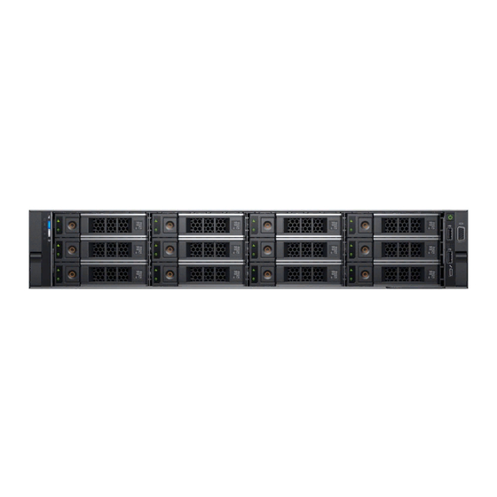
Chassis overview The PowerEdge R7425 is a dual socket, 2U rack server with up to 32 DIMM slots, storage capacity of up to 32 drive slots (front, mid, and rear storage options), and AMD Naples socket SP3 compatible processors. Table 4. R7425 chassis options 8 drives system Up to eight 3.5 inch or 2.5 inch (SAS, SATA or Nearline SAS) front accessible drives in slots... - Page 14 Figure 5. Front view of 12 x 3.5 inch drive system Figure 6. Front view of 8 x 3.5 inch drive system Table 5. Features available on the front of the system Item Panels and slots Icon Description Left control panel Contains system health and system ID, status LED, and the optional iDRAC Quick Sync 2 (wireless).
-
Page 15: Left Control Panel View
Left control panel view Figure 7. Left control panel without optional iDRAC Quick Sync 2.0 indicator Figure 8. Left control panel with optional iDRAC Quick Sync 2.0 indicator Table 6. Left control panel Item Indicator, button, or Icon Description connector Status LED indicators Indicate the status of the system. - Page 16 Icon Description Condition Corrective action • Run the appropriate Online Diagnostics test. Restart the system and run embedded diagnostics (ePSA). • If the drives are configured in a RAID array, restart the system, and enter the host adapter configuration utility program. Temperature The indicator turns solid amber if Ensure that none of the following conditions exist:...
- Page 17 iDRAC Quick Sync 2 indicator codes iDRAC Quick Sync 2 module (optional) is located on the left control panel of your system. Figure 10. iDRAC Quick Sync 2 indicator Table 9. iDRAC Quick Sync 2 indicators and descriptions iDRAC Quick Sync 2 indicator Condition Corrective action code...
-
Page 18: Right Control Panel View
Right control panel view Figure 11. Right control panel view Table 10. Right control panel features Item Indicator, button, or Icon Description connector Indicates if the system is turned on or off. Press the power button Power button to manually turn on or off the system. NOTE: Press the power button to gracefully shut down an ACPI-compliant operating system. -
Page 19: Back View Of The System
Table 11. iDRAC Direct LED indicator codes iDRAC Direct LED Condition indicator code Solid green for two Indicates that the laptop or tablet is connected. seconds Flashing green (on for two Indicates that the laptop or tablet connected is recognized. seconds and off for two seconds) Turns off... - Page 20 Table 12. Features available on the back view Item Panels, ports and slots Icon Description Full-height PCIe expansion The PCIe expansion card slot (riser 1) connects up to three full-height card slot (3) PCIe expansion cards to the system. Half-height PCIe The PCIe expansion card slot (riser 2) connects one half-height PCIe expansion card slot expansion cards to the system.
-
Page 21: Nic Indicator Codes
NIC indicator codes Each NIC on the back panel has indicators that provide information about the activity and link status. The activity LED indicator indicates if data is flowing through the NIC, and the link LED indicator indicates the speed of the connected network. Figure 15. - Page 22 Power indicator codes Condition Not illuminated Power is not connected to the PSU. Blinking green When the firmware of the PSU is being updated, the PSU handle blinks green. CAUTION: Do not disconnect the power cord or unplug the PSU when updating firmware. If firmware update is interrupted, the PSUs do not function.
-
Page 23: Drive Indicator Codes
Power indicator codes Condition Blinking green When hot-plugging a PSU, the PSU indicator blinks green. This indicates that there is a PSU mismatch with respect to efficiency, feature set, health status, or supported voltage. CAUTION: If two PSUs are installed, both the PSUs must have the same type of label; for example, Extended Power Performance (EPP) label. -
Page 24: Lcd Panel
Drive status indicator code Condition NOTE: The drive status indicator remains off until all drives are initialized after the system is turned on. Drives are not ready for removal during this time. Flashes green, amber, and then turns off Predicted drive failure. Flashes amber four times per second Drive failed. -
Page 25: Inside The System
Item Button or display Description LCD display Displays system information, status, and error messages or iDRAC IP address. Inside the system Figure 20. Inside the system - Configuration showing air shroud backplane backplane expander cooling fan (6) in the cooling fan assembly air shroud network daughter card riser 1... - Page 26 Figure 21. Inside the system – Configuration showing mid drive tray and rear drive cage backplane backplane expander cooling fan (6) in the cooling fan assembly drive (4) in the mid drive tray mid drive backplane rear drive backplane drive (2 x 3.5 inch or 4 x 2.5 inch) in the rear drive cage system board riser 1...
-
Page 27: Processors
Processors ™ The PowerEdge 14G systems feature the high performance AMD EPYC processor. The processor family is architected for exceptional workload-optimized performance and hardware-enhanced security. These processors are designed for next-generation data centers running on, software defined infrastructure supercharged for efficiency, performance, and agile services delivery across demanding workloads and applications. -
Page 28: System Memory
System memory The Dell EMC PowerEdge R7425 supports DDR4 registered DIMM (RDIMMs) slots and load reduced DIMM (LRDIMMs) slots. System memory holds the instructions that are executed by the processor. NOTE: MT/s indicates DIMM speed in MegaTransfers per second. Memory bus operating frequency can be 2666 MT/s, 2400 MT/s, or 2133 MT/s depending on the following factors: •... - Page 29 Figure 22. Memory socket locations Memory channels are organized as follows: Table 19. Memory channels Proc Channel 0 Channel 1 Channel 2 Channel 3 Channel 4 Channel 5 Channel 6 Channel 7 esso Proc Slots A5 and Slots A6 and Slots A7 and Slots A8 and Slots A1 and...
-
Page 30: General Memory Module Installation Guidelines
The PowerEdge R7425 system supports Flexible Memory Configuration, enabling the system to be configured and run in any valid chipset architectural configuration. The following are the recommended guidelines for installing memory modules: •... - Page 31 Feature Description Memory sparing (rank) Memory sparing allocates one rank per channel as a spare. If excessive correctable errors occur in a rank or channel, they are moved to the spare area while the operating system is running to prevent the errors from causing an uncorrectable failure. Memory thermal throttling This feature helps to optimize power/performance and can also be used to prevent DIMMs from overheating.
-
Page 32: Storage
Storage The PowerEdge R7425 system provides storage expandability that allows customer to adapt it to their workload and operational demands. With comprehensive storage options, the system offers various drive types, internal and external storage controllers, and different chassis and backplanes for varied numbers of drives. -
Page 33: Idsdm With Vflash Card
16/32/64 GB while for vFlash the capacity is limited to 16 GB only. The write-protect switch is built on the IDSDM with vFlash module. Optical Drives The PowerEdge R7425 supports one of the following internal optical drive options: • DVD-ROM •... -
Page 34: Boot Optimized Storage Subsystem
Boot Optimized Storage Subsystem The Boot Optimized Storage Subsystem (BOSS) is an alternative, high speed location to install the operating system. This ensures that the drive based storage is not used by the operating system. NOTE: The BOSS is recommended for non-virtualized operating systems. Virtualized operating systems are best supported by the IDSDM. - Page 35 Function/Feature Supported Dual non-RAID Degraded RAID1 and non-RAID Foreign import Consistency check Patrol read Load balance Rebuild NOTE: Manually triggered in Human Interface Infrastructure(HII) or via Marvell Command Line Interface (CLI). Auto-rebuild NOTE: Auto Rebuild will occur at power up only if there is a surviving native virtual disk and another physical disk is present at power up.
- Page 36 Function/Feature Supported TRIM and UNMAP virtual disk TRIM and UNMAP Non-RAID physical disk Yes Self-encrypting drives(SED) support Cryptographic erase (sanitize) NOTE: If drive supports SANITIZE Crypto Erase. No other encryption support from controller or drive.
-
Page 37: Networking And Pcie
NOTE: You can install up to eight PCIe add-on NIC cards. PCIe Expansion cards The Dell EMC PowerEdge R7425 system supports up to eight PCI express (PCIe) generation 3 expansion cards slots. The list below shows the available PCIe slots for R7425: Riser 1 •... -
Page 38: Trusted Platform Module
Trusted platform module The Trusted Platform Module (TPM) is used to generate and store keys, protect or authenticate passwords, and create and store digital certificates. The Intel’s TXT (Trusted Execution Technology) functionality along with Microsoft’s Platform Assurance feature in Windows Server 2016 is supported. TPM can also be used to enable the BitLocker hard drive encryption feature in Windows Server 2012/2016. -
Page 39: Power, Thermal, And Acoustics
Power consumption and energy efficiency With the rise in the cost of energy coupled with increasing data center density, Dell EMC provides tools and technologies to help you realize greater performance with lower energy cost and wastage. More efficient data center usage can reduce costs by slowing the need for additional data center space. -
Page 40: Power Supply Units
Acoustical design Dell EMC focuses on sound quality in addition to sound power level and sound pressure level. Sound quality describes how disturbing or pleasing a sound is interpreted, and Dell EMC references a number of psychacoustical metrics and thresholds in delivering to it. - Page 41 Whispering, open office layout, normal living room Quiet office Quiet library Recording studio...
-
Page 42: Rack Rails
Rack rails The rail offerings for the R7425 consist of two general types: sliding and static Sliding rails features summary The sliding rails (two varieties are offered) allow the system to be fully extended out of the rack for service. They are available with or without the optional cable management arm (CMA). -
Page 43: Static Rails
Dell racks. Also supports tool-less installation in threaded round hole 4-post racks. • Required for installing R7425 in a Dell EMC Titan or Titan-D rack. • Support full extension of the system out of the rack to allow serviceability of key internal components. -
Page 44: System-To-Rail Installation Method
Figure 26. Static rails in 2-post center mount configuration Installation in the Dell EMC Titan or Titan-D racks If installing to Titan or Titan-D racks, the Stab-in/Drop-in Sliding rails (B13) must be used. This rail collapses down sufficiently to fit in racks with mounting flanges spaced about 24 inches apart from front to back. -
Page 45: Cable Management Arm (Cma)
• Type and location of any equipment mounted in the back of the rack such as power distribution units (PDUs) • Overall depth of the rack The static rails offer a greater adjustability range and a smaller overall mounting footprint than the sliding rails. This is because of their reduced complexity and lack of need for CMA support. -
Page 46: Rack Installation
Figure 27. Sliding rails with CMA Rack Installation The R7425 offers two different varieties of sliding rails: ReadyRail Sliding rails (B6), and combination Stab-in/Drop-in Sliding rails (B13). Only one variety of static rail is offered: ReadyRails Static rails (B4). A "drop-in" design means that the system is installed vertically into the rails by inserting the standoffs on the sides of the system into the "J-slots"... - Page 47 Figure 28. Pull out inner rail Locate the rear rail standoff on each side of the system and lower them into the rear J-slots on the slide assemblies. Rotate the system downward until all the rail standoffs are seated in the J-slots. Figure 29.
-
Page 48: Installing The System Into The Rack (Option B: Stab-In)
Push the system inward until the lock levers click into place. Pull the blue slide release lock tabs forward on both rails and slide the system into the rack until the system is in the rack. Figure 30. Slide system into the rack Installing the system into the rack (option B: Stab-In) Pull the intermediate rails out of the rack until they lock into place. - Page 49 Figure 31. Pull out the intermediate rail Table 28. Rail component Number Component Intermediate rail Inner rail Attach the inner rails to the sides of the system by aligning the J-slots on the rail with the standoffs on the system and sliding forward on the system until they lock into place.
- Page 50 Figure 32. Attach the inner rails to the system With the intermediate rails extended, install the system into the extended rails.
- Page 51 Figure 33. Install system into the extended rails Pull the blue slide release lock tabs forward on both the rails, and slide the system into the rack.
- Page 52 Figure 34. Slide system into the rack...
-
Page 53: Dell Emc Openmanage Systems Management
Dell EMC OpenManage systems management Whether your IT environment consists of a few servers or a few thousand servers, Dell EMC OpenManage systems management solutions provide comprehensive management for evolving IT environments. OpenManage is based on open standards and provides agent-based and agent-free server lifecycle management functionality for Dell EMC PowerEdge servers. -
Page 54: Idrac With Lifecycle Controller
Lifecycle controller The integrated Dell Remote Access Controller 9 (iDRAC9) with Lifecycle Controller is embedded within every Dell EMC PowerEdge server and provides functionality that helps IT administrators deploy, update, monitor, and maintain servers with no need for any additional software to be installed. - Page 55 Features iDRAC8 iDRAC9 iDRAC8 iDRAC9 iDRAC8 iDRAC9 iDRAC8 iDRAC9 Basic Basic Express Express Express for Express Enterprise Enterprise Blades for Blades iDRAC Direct-Front panel Connection View NFS v4 NTLM v1 and NTLM v2 Security Role-based authority Local users SSL encryption IP blocking Directory services—AD, LDAP...
- Page 56 Features iDRAC8 iDRAC9 iDRAC8 iDRAC9 iDRAC8 iDRAC9 iDRAC8 iDRAC9 Basic Basic Express Express Express for Express Enterprise Enterprise Blades for Blades VNC connection to OS Quality/bandwidth control Virtual Console collaboration—6 users Virtual Console chat Virtual Flash partitions Group manager HTTP/HTTPS support along with NFS/CIFS Power and Thermal Real-time power meter...
- Page 57 Features iDRAC8 iDRAC9 iDRAC8 iDRAC9 iDRAC8 iDRAC9 iDRAC8 iDRAC9 Basic Basic Express Express Express for Express Enterprise Enterprise Blades for Blades Customizable settings for Exhaust Temperature Update Remote agent-free update Embedded update tools Sync with repository— scheduled updates Auto update Improved PSU firmware updates Deployment and Configuration...
- Page 58 Features iDRAC8 iDRAC9 iDRAC8 iDRAC9 iDRAC8 iDRAC9 iDRAC8 iDRAC9 Basic Basic Express Express Express for Express Enterprise Enterprise Blades for Blades LED health status indicator LCD screen—iDRAC9 requires optional bezel Quick Sync—require NFC bezel (13 G only) Quick Sync 2.0—requires BLE/WiFi hardware iDRAC Direct—front USB mgmt port...
-
Page 59: Dell Emc Consoles
The central console in a systems management solution is often referred to as the one-to-many console. The central console provides a rapid view and insight into the overall health of all systems in the IT environment. The Dell EMC systems management portfolio... -
Page 60: Dell Emc Openmanage Systems Management Tools, Utilities And Protocols
For more information, see OpenManage Power Center User’s Guide available at Dell.com/openmanagemanuals. Dell EMC OpenManage systems management tools, utilities and protocols Dell EMC OpenManage systems management tools and utilities consist of the following: Dell EMC Repository Manager: Dell EMC Repository Manager (DRM) is an application that helps you to: •... - Page 61 • Custom Server Update Utility (SUU) For more information, see Dell EMC Repository Manager User’s Guide available at Dell.com/support/manuals. Dell Update Packages Dell Update Packages (DUP) is a self-contained executable supported by Microsoft Windows or Linux that updates a component on a server and applications like OMSA, iSM, and DSET.
-
Page 62: Integration With Third-Party Consoles
Dell EMC server systems to your existing IT environment. Integrate new systems at your own pace. Manage new Dell EMC servers and storage with your legacy management tools, while extending the useful life of your existing resources. - Page 63 • OpenManage Connection for Nagios Core and Nagios XI • OpenManage Connection for HPE Operations Manager i (OMi) For more information on these OpenManage Connections, visit Dell.com/openmanage.
-
Page 64: Appendix A. Additional Specifications
Appendix A. Additional specifications The following sections contain information about additional system specifications. PSU specifications The PowerEdge R7425 system supports up to two AC or DC power supply units (PSUs). Table 30. PSU specifications Class Heat Frequency Voltage High line... -
Page 65: System Dimensions
NOTE: PSUs rated for 1100 W AC or 1100 W Mixed Mode HVDC and higher require high-line voltage (200–240 V AC) to supply their rated capacity. System dimensions This section describes the physical dimensions of the system. Figure 36. System dimensions of PowerEdge R7425 system Table 31. Dimensions System Za (with... -
Page 66: Chassis Weight
See Dell EMC PowerEdge R7425 installation service manuals on Dell.com/Support/Manuals for detailed environmental specifications. Video specifications The PowerEdge R7425 system supports integrated Matrox G200eW3 graphics controller with 16 MB of video frame buffer. Table 33. Supported video resolution options Resolution Refresh rate (Hz) Color depth (bits) -
Page 67: Appendix B. Standards Compliance
Appendix B. Standards compliance Table 34. Industry standard documents Standard URL for information and specifications ACPI Advance Configuration and Power Interface Specification, acpi.info v2.0c Ethernet IEEE 802.3-2005 standards.ieee.org/getieee802/802.3.html HDG Hardware Design Guide Version 3.0 for Microsoft Windows microsoft.com/whdc/system/platform/pcdesign/desguide/ Server serverdg.mspx IPMI Intelligent Platform Management Interface, v2.0 intel.com/design/servers/ipmi DDR4 Memory DDR4 SDRAM Specification... -
Page 68: Appendix C Additional Resources
Appendix C Additional resources Table 35. Additional resources Resource Description of contents Location This manual, available in PDF format, provides the following PowerEdge R7425 Installation Dell.com/Support/Manuals information: Service Manuals • Chassis features • System Setup program • System messages •... -
Page 69: Appendix D. Support And Deployment Services
Remote Consulting Services When you are in the final stages of your PowerEdge server implementation, you can rely on Dell EMC Remote Consulting and our certified technical experts to help you optimize your configuration with best practices for your software, virtualization, server,... -
Page 70: Data Migration Service
ProSupport Enterprise Suite With Dell EMC ProSupport Services, we can help you keep your operation running smoothly, so you can focus on running your business. We will help you maintain peak performance and availability of your most essential workloads. Dell EMC ProSupport is a suite of support services that enable you to build the solution that is right for your organization. -
Page 71: Prosupport
Dell EMC ProSupport Flex for Data Center offers flexible site-wide support for hyperscale data centers with more than 1,000 assets. Built on standard Dell EMC ProSupport components, Flex for Data Center leverages our global scale while being tailored to suit your needs. -
Page 72: Dell Emc Global Infrastructure Consulting Services
Dell EMC managed services Dell EMC Managed Services are a modular set of lifecycle services designed to help you automate and centrally configure, deploy, and manage your day-to-day data center operations. These services extend your existing on-premise IT infrastructure with off- premise cloud services designed to better address challenges with mobility, highly distributed organizations, security, compliance, business continuity, and disaster preparedness.
Need help?
Do you have a question about the PowerEdge R7425 and is the answer not in the manual?
Questions and answers