
Related Manuals for Dell EMC PowerEdge R740xd


Summary of Contents for Dell EMC PowerEdge R740xd
- Page 1 Dell EMC PowerEdge R740xd Installation and Service Manual Regulatory Model: E38S Series Regulatory Type: E38S001 May 2020 Rev. A11...
- Page 2 Notes, cautions, and warnings NOTE: A NOTE indicates important information that helps you make better use of your product. CAUTION: A CAUTION indicates either potential damage to hardware or loss of data and tells you how to avoid the problem. WARNING: A WARNING indicates a potential for property damage, personal injury, or death.
-
Page 3: Table Of Contents
Contents Chapter 1: PowerEdge R740xd system overview................8 Supported configurations..............................8 Front view of the system..............................10 Left control panel view..............................11 Right control panel view..............................13 Back view of the system..............................14 NIC indicator codes................................16 Power supply unit indicator codes..........................17 Drive indicator codes................................ - Page 4 iDRAC configuration................................41 Options to set up iDRAC IP address..........................41 Log in to iDRAC................................42 Options to install the operating system..........................42 Methods to download firmware and drivers......................42 Downloading drivers and firmware..........................43 Chapter 5: Pre-operating system management applications............. 44 Options to manage the pre-operating system applications...................
- Page 5 Installing a cooling fan..............................85 Intrusion switch................................... 86 Removing an intrusion switch............................86 Installing an intrusion switch............................87 NVDIMM-N battery................................88 NVDIMM-N battery details............................88 Removing the NVDIMM-N battery from the air shroud...................88 Installing NVDIMM-N battery into air shroud......................89 Removing NVDIMM-N battery from mid drive tray....................90 Installing NVDIMM-N battery into mid drive tray.......................91 Removing NVDIMM-N battery from the bracket.....................
- Page 6 Removing the processor from the processor and heat sink module..............128 Installing the processor into a processor and heat sink module................129 Installing a processor and heat sink module......................131 Expansion cards and expansion card risers........................133 Expansion card installation guidelines........................133 Opening and closing the PCIe card holder latch......................
- Page 7 System board jumpers and connectors........................... 211 System board jumper settings............................213 Disabling forgotten password............................213 Chapter 9: Getting help........................214 Contacting Dell EMC................................. 214 Documentation feedback..............................214 Accessing system information by using QRL......................... 214 Quick Resource Locator for PowerEdge R740 and R740xd systems..............215 Receiving automated support with SupportAssist ....................... 215 Recycling or End-of-Life service information.........................215...
-
Page 8: Chapter 1: Poweredge R740Xd System Overview
PowerEdge R740xd system overview The PowerEdge R740xd is a 2U rack server that supports up to: • Two Intel Xeon Scalable Processors • 24 DIMM slots • Two AC or DC power supply units • 32 SAS, SATA, Nearline SAS hard drives or SSDs, and up to 24 NVMe drives. For more information about supported drives, see the Technical specifications section. - Page 9 Figure 1. Supported configurations PowerEdge R740xd system overview...
-
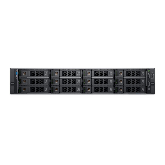
Page 10: Front View Of The System
Contains system health and system ID, status LED or optional iDRAC Quick Sync 2 (wireless). Drive slots Enable you to install drives that are supportedon your system. For more information about drives, see the Technicalspecifications section. PowerEdge R740xd system overview... -
Page 11: Left Control Panel View
The indicator turns solid amber if • Check the System Event Log to determine if the drive has an error. indicator there is a drive error. • Run the appropriate Online Diagnostics test. Restart the system and run embedded diagnostics (ePSA). PowerEdge R740xd system overview... - Page 12 Event Log or the LCD panel, if available on the bezel, for specific error messages. For more information about error messages, see the Event and Error Message Reference Guide for 14th Generation Dell EMC PowerEdge Servers at www.dell.com/qrl. PowerEdge R740xd system overview...
-
Page 13: Right Control Panel View
Getting help. Blinking amber Indicates that the iDRAC Quick Sync 2 Restart the system. If the problem persists, see hardware is not responding properly. Getting help. Right control panel view Figure 7. Right control panel view PowerEdge R740xd system overview... -
Page 14: Back View Of The System
Indicates that the laptop or tablet connected is recognized. seconds and off for two seconds) Turns off Indicates that the laptop or tablet is unplugged. Back view of the system Figure 8. Back view of 4 x 2.5 inch drive system PowerEdge R740xd system overview... - Page 15 Expansion card installation guidelines section. Half-height PCIe expansion The PCIe expansion card slot (riser 2) connects one half-height PCIe card slot expansion cards to the system. For more information, see the Expansion card installation guidelines section. PowerEdge R740xd system overview...
-
Page 16: Nic Indicator Codes
Link indicator is amber and activity indicator is off The NIC is connected to a valid network at less than its maximum port speed and data is not being sent or received. PowerEdge R740xd system overview... -
Page 17: Power Supply Unit Indicator Codes
CAUTION: If two PSUs are used, they must be of the same type and have the same maximum output power. CAUTION: Combining AC and DC PSUs is not supported and triggers a mismatch. PowerEdge R740xd system overview... - Page 18 Output configuration or vice versa, you must turn off the system. CAUTION: If two PSUs are used, they must be of the same type and have the same maximum output power. CAUTION: Combining AC and DC PSUs is not supported and triggers a mismatch. PowerEdge R740xd system overview...
-
Page 19: Drive Indicator Codes
Look it up.. The LCD panel is available only on the optional front bezel. The optional front bezel is hot pluggable. The statuses and conditions of the LCD panel are outlined here: PowerEdge R740xd system overview... -
Page 20: Viewing Home Screen
On the Home screen, press the Select button to enter the main menu. Setup menu NOTE: When you select an option in the Setup menu, you must confirm the option before proceeding to the next action. PowerEdge R740xd system overview... -
Page 21: View Menu
Select Simple to view LCD error messages in a simplified user-friendly description. For more information about error messages, see the Event and Error Message Reference Guide for 14th Generation Dell EMC PowerEdge Servers at www.dell.com/qrl. Set home Select the default information to be displayed on the Home screen. See View menu section for the options and option items that can be set as the default on the Home screen. -
Page 22: System Information Label
System information label PowerEdge R740xd – Front system information label LED behavior, express service tag, hard drives configuration and layout Figure 16. LED behavior Figure 17. 2.5 inch hard drives configuration and layout Figure 18. 3.5 inch hard drives configuration and layout PowerEdge R740xd –... - Page 23 Figure 19. Service Information Figure 20. Jumper setting and memory information PowerEdge R740xd system overview...
- Page 24 Figure 21. system task Figure 22. NVDIMM battery and mid-tray hard drives PowerEdge R740xd system overview...
-
Page 25: Chapter 2: Documentation Resources
To view the document that is listed in the documentation resources table: • From the Dell EMC support site: 1. Click the documentation link that is provided in the Location column in the table. 2. Click the required product or product version. - Page 26 Dell OpenManage Enterprise, see OpenManage Enterprise the Dell OpenManage Enterprise User’s Guide. For information about installing and using Dell https://www.dell.com/serviceabilitytools SupportAssist, see the Dell EMC SupportAssist Enterprise User’s Guide. For information about partner programs enterprise www.dell.com/openmanagemanuals systems management, see the OpenManage Connections Enterprise Systems Management documents.
-
Page 27: Chapter 3: Technical Specifications
Technical specifications The technical and environmental specifications of your system are outlined in this section. Topics: • System dimensions • Chassis weight • Processor specifications • Supported operating systems • PSU specifications • System battery specifications • Expansion bus specifications •... -
Page 28: Chassis Weight
28.1 kg (61.95 lb) 3.5 inch drive systems 33.1 kg (72.91 lb) Processor specifications The PowerEdge R740xd system supports up to two Intel Xeon Processor Scalable Family processors, up to 28 cores per processor. NOTE: Processor sockets are not hot pluggable. Technical specifications... -
Page 29: Supported Operating Systems
SUSE Linux Enterprise Server VMware ESXi NOTE: For more information, go to www.dell.com/ossupport. PSU specifications The PowerEdge R740xd system supports up to two AC or DC power supply units (PSUs). Table 19. PSU specifications Class Heat Frequenc Voltage High line... -
Page 30: System Battery Specifications
Expansion bus specifications The PowerEdge R740xd system supports up to eight PCI express (PCIe) generation 3 expansion cards that can be installed on the system board using expansion card risers. The following table provides detailed information about the expansion card riser specifications: Table 20. - Page 31 Table 21. Expansion card riser specifications Riser Slot PCIe slots on Processor PCIe slots on Processor PCIe slots on Processo configuration description riser 1 (Height connectio riser 2 (Height connectio riser 3 (Height and supported and length) and length) and length) connectio risers Riser...
-
Page 32: Memory Specifications
Table 21. Expansion card riser specifications (continued) Riser Slot PCIe slots on Processor PCIe slots on Processor PCIe slots on Processo configuration description riser 1 (Height connectio riser 2 (Height connectio riser 3 (Height and supported and length) and length) and length) connectio risers... -
Page 33: Storage Controller Specifications
External storage controller cards: PERC H840 and 12Gbps SAS HBA. NOTE: Mini-PERC socket is not hot pluggable. Drive specifications Drives The PowerEdge R740XD system supports SAS, SATA, Nearline SAS hard drives/SSDs, or NVMe drives. Table 23. Supported drive options for the PowerEdge R740XD system Configuration Description 12 drives system Up to 12 3.5 inch (SAS, SATA or Nearline SAS) front accessible drives in slots 0 to 11... -
Page 34: Ports And Connectors Specifications
NDC slot is not hot pluggable. VGA ports The Video Graphic Array (VGA) port enables you to connect the system to a VGA display. The PowerEdge R740xd system supports two 15-pin VGA ports on the front and back panels. NOTE: The VGA ports are not hot pluggable. -
Page 35: Internal Dual Sd Module Or Vflash Card
Internal Dual SD Module or vFlash card The PowerEdge R740xd system supports Internal Dual SD module (IDSDM) and vFlash card. In 14th generation of PowerEdge servers, IDSDM and vFlash card are combined into a single card module, and are available in these configurations: •... -
Page 36: Standard Operating Temperature
Table 26. Relative humidity specifications Relative humidity Specifications Storage 5% to 95% RH with 33°C (91°F) maximum dew point. Atmosphere must be non-condensing at all times. Operating 10% to 80% relative humidity with 29°C (84.2°F) maximum dew point. Table 27. Maximum vibration specifications Maximum vibration Specifications Operating... - Page 37 Table 32. Expanded operating temperature specifications (continued) Expanded operating temperature Specifications NOTE: Outside the standard operating temperature (10°C to 35°C), the system can operate continuously in temperatures as low as 5°C and as high as 40°C. For temperatures between 35°C to 40°C, de-rate maximum allowable temperature by 1°C per 175 m above 950 m (1°F per 319 ft).
- Page 38 Table 33. Thermal restrictions configuration (continued) Configuration Number Heatsink Processor/DIMM DIMM Type of air blank blanks shroud processor One 2U standard heat sink blank to cover for CPU > 125 W two fan slots PowerEdge Two 1U standard heat sink R740xd for CPU ≤...
-
Page 39: Particulate And Gaseous Contamination Specifications
Table 35. NIC card slot restrictions System Configuration Slot restriction Ambient restriction PowerEdge R940 Eight 2.5-inch hard drive Slots 1, 5, and 6 do not 35°C system support NIC cards Twenty four 2.5-inch hard Slots 1, 5, and 6 do not 35°C drive system support NIC cards... - Page 40 Table 38. Particulate contamination specifications (continued) Particulate contamination Specifications to IT equipment designed to be used outside a data center, in environments such as an office or factory floor. NOTE: Air entering the data center must have MERV11 or MERV13 filtration. Conductive dust Air must be free of conductive dust, zinc whiskers, or other conductive particles.
-
Page 41: Chapter 4: Initial System Setup And Configuration
Initial system setup and configuration Topics: • Setting up your system • iDRAC configuration • Options to install the operating system Setting up your system Perform the following steps to set up your system: Steps 1. Unpack the system. 2. Install the system into the rack. For more information about installing the system into the rack, see the Rail Installation Guide at www.dell.com/poweredgemanuals. -
Page 42: Log In To Idrac
Dell certified VMware ESXi www.dell.com/virtualizationsolutions Installation and How-to videos for supported operating systems on Supported Operating Systems for Dell EMC PowerEdge systems PowerEdge systems Methods to download firmware and drivers You can download the firmware and drivers by using any of the following methods: Table 41. -
Page 43: Downloading Drivers And Firmware
Using iDRAC virtual media www.dell.com/idracmanuals Downloading drivers and firmware Dell EMC recommends that you download and install the latest BIOS, drivers, and systems management firmware on your system. Prerequisites Ensure that you clear the web browser cache before downloading the drivers and firmware. -
Page 44: Chapter 5: Pre-Operating System Management Applications
System Setup By using the System Setup screen, you can configure the BIOS settings, iDRAC settings, and device settings of your system. These settings have already been pre-configured per solution requirements. Contact Dell EMC before you change these settings. NOTE: Help text for the selected field is displayed in the graphical browser by default. -
Page 45: Viewing System Setup
Viewing System Setup To view the System Setup screen, perform the following steps: Steps 1. Power on, or restart your system. 2. Press F2 immediately after you see the following message: F2 = System Setup NOTE: If your operating system begins to load before you press F2, wait for the system to finish booting, and then restart your system and try again. - Page 46 Serial Communication on page 60 System Profile Settings on page 61 Miscellaneous Settings on page 67 iDRAC Settings utility on page 67 Device Settings on page 68 System Security on page 62 Related tasks Viewing System BIOS on page 46 Viewing System BIOS To view the System BIOS screen, perform the following steps: Steps...
- Page 47 Option Description Redundant OS Sets the redundant OS information for redundant OS control. Control Miscellaneous Provides options to change the system date and time. Settings System Information You can use the System Information screen to view system properties such as Service Tag, system model name, and BIOS version. Viewing System Information To view the System Information screen, perform the following steps: Steps...
- Page 48 Memory Settings You can use the Memory Settings screen to view all the memory settings and enable or disable specific memory functions, such as system memory testing and node interleaving. Viewing Memory Settings To view the Memory Settings screen, perform the following steps: Steps 1.
- Page 49 Option Description Node Interleaving Specifies if Non-Uniform Memory Architecture (NUMA) is supported. If this field is set to Enabled, memory interleaving is supported if a symmetric memory configuration is installed. If this field is set to Disabled, the system supports NUMA (asymmetric) memory configurations. This option is set to Disabled by default. ADDDC Setting Enables or disables ADDDC Setting feature.
- Page 50 Option Description The options available are Maximum data rate, 10.4 GT/s, and 9.6 GT/s. This option is set to Maximum data rate by default. Maximum data rate indicates that the BIOS runs the communication links at the maximum frequency that is supported by the processors.
- Page 51 Option Description Dell Controlled Controls the turbo engagement. Enable this option only when System Profile is set to Disabled. Turbo NOTE: Depending on the number of installed processors, there might be up to fourtwo processor listings. Dell AVX Scaling Enables you to configure the Dell AVX scaling technology. This option is set to 0 by default. Technology Number of Cores Controls the number of enabled cores in each processor.
- Page 52 Option Description Embedded SATA Enables the embedded SATA option to be set to AHCI Mode, or RAID Mode. This option is set to AHCI Mode by default. Security Freeze Enables you to send Security Freeze Lock command to the embedded SATA drives during POST. This option is Lock applicable only for AHCI mode.
- Page 53 ○ Enhanced security (e.g., UEFI Secure Boot). ○ Faster boot time. NOTE: You must use only the UEFI boot mode in order to boot from NVMe drives. • BIOS: The BIOS Boot Mode is the legacy boot mode. It is maintained for backward compatibility. Viewing Boot Settings To view the Boot Settings screen, perform the following steps: Steps...
- Page 54 UEFI Boot Enables you to change the boot device order. Sequence Boot Options Enables you to select the enabled or disabled boot devices. Enable/Disable Choosing system boot mode System Setup enables you to specify one of the following boot modes for installing your operating system: •...
- Page 55 Network Settings screen details The Network Settings screen details are explained as follows: About this task Option Description UEFI PXE Settings Options Description PXE Device n (n = Enables or disables the device. When enabled, a UEFI PXE boot option is created for the 1 to 4) device.
- Page 56 Option Description Table 44. UEFI iSCSI Settings screen details (continued) Option Description Connection 2 Enables or disables the iSCSI device. When disabled, a UEFI boot option is created for the iSCSI device automatically. This is set to Disabled by default. Connection 1 Settings Enables you to control the configuration of the iSCSI device.
- Page 57 Option Description iDRAC Direct USB The iDRAC Direct USB port is managed by iDRAC exclusively with no host visibility. This option is set to ON or Port OFF. When set to OFF, iDRAC does not detect any USB devices installed in this managed port. This option is set to On by default.
- Page 58 Option Description Table 45. Slot Disablement Option Description Slot 1 Enables or disables the PCIe slot 1. This option is set to Enabled by default. Slot 3 Enables or disables or only the boot driver is disabled for the PCIe slot 3. This option is set to Enabled by default.
- Page 59 Option Description Table 46. Slot Disablement (continued) Option Description Slot 7 Enables or disables or only the boot driver is disabled for the PCIe slot 7. This option is set to Enabled by default. NOTE: If your system supports four processors, you may have 13 PCIe slots. Slot Bifurcation Allows Platform Default Bifurcation, Auto Discovery of Bifurcation and Manual Bifurcation Control.
- Page 60 Serial Communication You can use the Serial Communication screen to view the properties of the serial communication port. Viewing Serial Communication To view the Serial Communication screen, perform the following steps: Steps 1. Power on, or restart your system. 2. Press F2 immediately after you see the following message: F2 = System Setup NOTE: If your operating system begins to load before you press F2, wait for the system to finish booting, and then...
- Page 61 System Profile Settings You can use the System Profile Settings screen to enable specific system performance settings such as power management. Viewing System Profile Settings To view the System Profile Settings screen, perform the following steps: Steps 1. Power on, or restart your system. 2.
- Page 62 Option Description Number of Turbo NOTE: If there are four processors installed in the system, you will see an entry for Number of Boost Enabled Turbo Boost Enabled Cores for Processor 4. Cores for Controls the number of turbo boost enabled cores for Processor 1. The maximum number of cores is enabled by Processor 1 default.
- Page 63 Option Description System Password Enables you to set the system password. This option is set to Enabled by default and is read-only if the password jumper is not installed in the system. Setup Password Enables you to set the system setup password. This option is read-only if the password jumper is not installed in the system.
- Page 64 Option Description Secure Boot When Secure Boot policy is set to Standard, the BIOS uses the system manufacturer key and certificates to Policy authenticate pre-boot images. When Secure Boot policy is set to Custom, the BIOS uses the user-defined key and certificates.
- Page 65 Related References System board jumper settings on page 213 Using your system password to secure the system About this task If you have assigned a setup password, the system accepts your setup password as an alternate system password. Steps 1. Power on or reboot your system. 2.
- Page 66 Related References System Security Settings details on page 62 Redundant OS Control In the Redundant OS Control screen you can set the redundant OS information. This enables you to set up a physical recovery disk on the system. Viewing Redundant OS Control To view the Redundant OS Control screen, perform the following steps: Steps 1.
-
Page 67: Idrac Settings Utility
Miscellaneous Settings You can use the Miscellaneous Settings screen to perform specific functions such as updating the asset tag and changing the system date and time. Viewing Miscellaneous Settings To view the Miscellaneous Settings screen, perform the following steps: Steps 1. -
Page 68: Device Settings
Related concepts Device Settings on page 68 System BIOS on page 45 Device Settings Device Settings enables you to configure the below device parameters: • Controller Configuration Utility • Embedded NIC Port1-X Configuration • NICs in slotX, Port1-X Configuration • BOSS Card configuration Related concepts System BIOS... -
Page 69: Boot Manager Main Menu
Steps 1. Power on, or restart your system. 2. Press F11 when you see the following message: F11 = Boot Manager If your operating system begins to load before you press F11, allow the system to complete the booting, and then restart your system and try again. -
Page 70: Pxe Boot
PXE boot You can use the Preboot Execution Environment (PXE) option to boot and configure the networked systems, remotely. To access the PXE boot option, boot the system and then press F12 during POST instead of using standard Boot Sequence from BIOS Setup. -
Page 71: Chapter 6: Installing And Removing System Components
Installing and removing system components Topics: • Safety instructions • Before working inside your system • After working inside your system • Recommended tools • Optional front bezel • System cover • Backplane cover • Inside the system • Air shroud •... -
Page 72: Before Working Inside Your System
NOTE: It is recommended that you always use an antistatic mat and antistatic strap while working on components inside the system. CAUTION: To ensure proper operation and cooling, all bays in the system and system fans must be always populated with a component or a blank. -
Page 73: Optional Front Bezel
Optional front bezel Front bezel details An optional metal bezel is mounted on the front of the system to display system branding. A lock on the bezel is used to protect unauthorized access to the drives. There are two versions of bezel available: •... -
Page 74: Installing The Front Bezel
Installing the front bezel The procedure to install the front bezel with and without the LCD panel is the same. Prerequisites Follow the safety guidelines listed in Safety instructions. Steps 1. Locate and remove the bezel key. NOTE: The bezel key is part of the LCD bezel package. 2. -
Page 75: Installing The System Cover
3. Hold the cover on both sides, and lift the cover away from the system. Figure 26. Removing the system cover Next steps Install the system cover. Installing the system cover Prerequisites 1. Follow the safety guidelines listed in Safety instructions. -
Page 76: Backplane Cover
Figure 27. Installing system cover Next steps 1. Reconnect the peripherals and connect the system to the electrical outlet. 2. Turn on the system, including any attached peripherals. Backplane cover Removing the backplane cover Prerequisites 1. Follow the safety guidelines listed in Safety instructions. -
Page 77: Installing The Backplane Cover
Figure 28. Removing backplane cover Next steps Install the backplane cover. Installing the backplane cover Prerequisites Follow the safety guidelines listed in Safety instructions. Steps 1. Align the tabs on the backplane cover with the guide slots on the system. 2. -
Page 78: Inside The System
Figure 29. Installing the backplane cover Next steps Follow the procedure listed in After working inside your system on page 72. Inside the system CAUTION: Many repairs may only be done by a certified service technician. You should only perform troubleshooting and simple repairs as authorized in your product documentation, or as directed by the online or telephone service and support team. - Page 79 Figure 30. Inside the system – NVDIMM-N battery 1. drive backplane 2. backplane expander card 3. cooling fan (6) in the cooling fan assembly 4. air shroud 5. expansion card riser 3 6. network daughter card 7. expansion card riser 2 8.
-
Page 80: Air Shroud
Figure 31. Inside the system – mid drive tray and rear drive cage 1. drive backplane 2. backplane expander card 3. cooling fan (6) in the cooling fan assembly 4. drive (4) in the mid drive tray 5. mid drive backplane 6. -
Page 81: Installing The Air Shroud
CAUTION: NVDIMM-N battery is not hot swappable. To prevent data loss and potential damage to your system, ensure that your system, LEDs on system, LEDs on NVDIMM-N and LEDs on NVDIMM-N battery are turned off before disconnecting the NVDIMM-N battery cables. Steps Hold the air shroud at both ends and lift it away from the system. -
Page 82: Cooling Fan Assembly
Figure 33. Installing air shroud Next steps 1. If removed, install the full length PCIe cards. 2. If applicable, install the GPU cards. 3. If applicable, connect the cables to the NVDIMM-N battery. CAUTION: NVDIMM-N battery is not hot swappable. To prevent data loss and potential damage to your system, ensure that your system, LEDs on system, LEDs on NVDIMM-N and LEDs on NVDIMM-N battery are turned off before connecting the NVDIMM-N battery cables. -
Page 83: Installing The Cooling Fan Assembly
Figure 34. Removing the cooling fan assembly Next steps Install the cooling fan assembly. Installing the cooling fan assembly Prerequisites Follow the safety guidelines listed in Safety instructions. CAUTION: Ensure that the cables inside the system are correctly installed and retained by the cable retention bracket before installing the cooling fan assembly. -
Page 84: Cooling Fans
Figure 35. Installing the cooling fan assembly Next steps Follow the procedure listed in After working inside your system. Cooling fans Cooling fan details The cooling fans are integrated into the system to dissipate the heat generated by the functioning of the system. These fans provide cooling for the processors, expansion cards, and memory modules. -
Page 85: Installing A Cooling Fan
CAUTION: The cooling fans are hot swappable. To maintain proper cooling while the system is on, replace only one fan at a time. 1. Follow the safety guidelines listed in Safety instructions. 2. Follow the procedure listed in Before working inside your system. -
Page 86: Intrusion Switch
Figure 37. Installing cooling fan 2. Slide the cooling fan into the cooling fan assembly until the release tab locks into place. Next steps Follow the procedure listed in After working inside your system on page 72. Intrusion switch Removing an intrusion switch Prerequisites 1. -
Page 87: Installing An Intrusion Switch
Figure 38. Removing an intrusion switch Next steps Install an intrusion switch. Installing an intrusion switch Prerequisites Follow the safety guidelines listed in Safety instructions. Steps 1. Align the tabs on the intrusion switch with the slots on the cooling fan assembly. 2. -
Page 88: Nvdimm-N Battery
Next steps Install the cooling fan assembly. 2. Follow the procedure listed in After working inside your system. NVDIMM-N battery NVDIMM-N battery details NVDIMM-N battery can be installed on air shroud and 3.5-inch mid hard drive tray. NOTE: NVDIMM-N battery is not supported on 2.5 inch NVMe mid hard drive tray. Removing the NVDIMM-N battery from the air shroud Prerequisites 1. -
Page 89: Installing Nvdimm-N Battery Into Air Shroud
Figure 40. Removing the NVDIMM-N battery from the air shroud Next steps Install the NVDIMM-N battery into the air shroud. Installing NVDIMM-N battery into air shroud Prerequisites Follow the safety guidelines listed in Safety instructions. CAUTION: NVDIMM-N battery is not hot swappable. To prevent data loss and potential damage to your system, ensure that your system, LEDs on system, LEDs on NVDIMM-N and LEDs on NVDIMM-N battery are turned off before installing the NVDIMM-N battery. -
Page 90: Removing Nvdimm-N Battery From Mid Drive Tray
Figure 41. Installing NVDIMM-N battery into air shroud Next steps Follow the procedure listed in After working inside your system. Removing NVDIMM-N battery from mid drive tray Prerequisites 1. Follow the safety guidelines listed in Safety instructions on page 71. 2. -
Page 91: Installing Nvdimm-N Battery Into Mid Drive Tray
Figure 42. Removing NVDIMM-N battery from mid drive tray Next steps Install NVDIMM-N battery into mid drive tray. Installing NVDIMM-N battery into mid drive tray Prerequisites Follow the safety guidelines listed in Safety instructions on page 71. CAUTION: NVDIMM-N battery is not hot swappable. To prevent data loss and potential damage to your system, ensure that your system, LEDs on system, LEDs on NVDIMM-N and LEDs on NVDIMM-N battery are turned off before installing the NVDIMM-N battery. -
Page 92: Removing Nvdimm-N Battery From The Bracket
Figure 43. Installing NVDIMM-N battery into mid drive tray Next steps Follow the procedure listed in After working inside your system on page 72. Removing NVDIMM-N battery from the bracket Prerequisites 1. Follow the safety guidelines listed in Safety instructions on page 71. -
Page 93: Installing Nvdimm-N Battery Into The Bracket
Figure 44. Removing NVDIMM-N battery from the bracket Next steps Install NVDIMM-N battery into the bracket.. Installing NVDIMM-N battery into the bracket Prerequisites Follow the safety guidelines listed in Safety instructions on page 71. CAUTION: NVDIMM-N battery is not hot swappable. To prevent data loss and potential damage to your system, ensure that your system, LEDs on system, LEDs on NVDIMM-N and LEDs on NVDIMM-N battery are turned off before installing the NVDIMM-N battery. -
Page 94: Mid Drive Tray
Figure 45. Installing NVDIMM-N battery into the bracket Next steps Follow the procedure listed in After working inside your system on page 72. Mid drive tray Mid drive tray details The mid drive tray is located behind the cooling fan assembly. It supports up to four 2.5 inch or four 3. NOTE: Systems that support the internal mid drive tray require low-profile heat sinks and do not require or support an air shroud. -
Page 95: Installing The Mid Drive Tray
Figure 46. Removing mid drive tray Next steps Install the mid drive tray. Installing the mid drive tray Prerequisites Follow the safety guidelines listed in Safety instructions. NOTE: Systems that support the internal drive tray support low-profile heat sinks and do not support an air shroud. Steps 1. -
Page 96: Removing Drive Blank From Drive Carrier
Figure 47. Installing the mid drive tray Next steps 1. Connect all the cables to the backplane. 2. Follow the procedure listed in After working inside your system. Removing drive blank from drive carrier The procedure to remove drive blank from drive carrier is identical to removal of drive from drive carrier. The procedure for removing 2.5 inch and 3.5 inch blanks from drive carriers is identical. -
Page 97: Installing Drive Blank Into The Drive Carrier
Figure 48. Removing drive blank from the mid drive carrier Next steps Install drive blank into drive carrier. Installing drive blank into the drive carrier The procedure to install drive blank from drive carrier is identical to installation of drive into drive carrier. The procedure for installing 2.5 inch and 3.5 inch blanks into drive carriers is identical. -
Page 98: Removing Drive Carrier From The Mid Drive Tray
Figure 49. Installing drive blank into the mid drive carrier Next steps Follow the procedure listed in After working inside your system. Removing drive carrier from the mid drive tray Prerequisites 1. Follow the safety guidelines listed in Safety instructions. 2. -
Page 99: Installing Drive Carrier Into Mid Drive Tray
CAUTION: To maintain proper system cooling, all empty drive slots must have drive blanks installed. 4. If you are not replacing the drive immediately, insert a drive blank in the empty drive slot. NOTE: Install the drive blanks in the drive carrier before installing the drive carrier into the drive tray. Figure 50. -
Page 100: Removing 3.5 Inch Drive From The Drive Carrier
Figure 51. Installing drive carrier into mid drive tray Next steps Follow the procedure listed in After working inside your system. Removing 3.5 inch drive from the drive carrier Prerequisites 1. Follow the safety guidelines listed in Safety instructions. 2. Follow the procedure listed in Before working inside your system. -
Page 101: Installing 3.5 Inch Drive Into The Drive Carrier
Figure 52. Removing 3.5 inch drive from the drive carrier Next steps Install 3.5 inch drive into the drive carrier. Installing 3.5 inch drive into the drive carrier Prerequisites Follow the safety guidelines listed in Safety instructions. CAUTION: Mixing drives from previous generations of PowerEdge servers is not supported. Steps 1. -
Page 102: Removing A 2.5 Inch Drive From The 3.5 Inch Mid Drive Carrier
Figure 53. Installing 3.5 inch drive into the drive carrier Next steps Follow the procedure listed in After working inside your system. Removing a 2.5 inch drive from the 3.5 inch mid drive carrier Prerequisites 1. Follow the safety guidelines listed in Safety instructions. -
Page 103: Installing A 2.5 Inch Drive Into The 3.5 Inch Mid Drive Carrier
Figure 54. Removing a 2.5 inch drive from the 3.5 inch mid drive carrier Next steps Install a 2.5 inch drive into the 3.5 inch mid drive carrier. Installing a 2.5 inch drive into the 3.5 inch mid drive carrier Prerequisites Follow the safety guidelines listed in Safety... -
Page 104: Drives
Figure 55. Installing a 2.5 inch drive into the 3.5 inch mid drive carrier Next steps Follow the procedure listed in After working inside your system. Drives Drive guidelines Drives are supplied in hot swappable drive carriers that fit in the drive slots. CAUTION: Before attempting to remove or install a drive while the system is running, see the documentation for the storage controller card to ensure that the host adapter is configured correctly. -
Page 105: Installing A Drive Blank
CAUTION: Mixing drive blanks from previous generations of PowerEdge servers is not supported. Steps Press the release button, and slide the drive blank out of the drive slot. Figure 56. Removing a drive blank Next steps Install a drive or a drive blank Installing a drive blank The procedure for installing 2.5 inch and 3.5 inch drive blanks is identical. -
Page 106: Removing A Drive Carrier
Removing a drive carrier Prerequisites 1. Follow the safety guidelines listed in Safety instructions. 2. If applicable, remove the front bezel. 3. Using the management software, prepare the drive for removal. If the drive is online, the green activity or fault indicator flashes while the drive is turning off. When the drive indicators are off, the drive is ready for removal. -
Page 107: Removing A 2.5 Inch Drive From The 3.5 Inch Drive Adapter
CAUTION: Combining SAS and SATA drives in the same RAID volume is not supported. CAUTION: When installing a drive, ensure that the adjacent drives are fully installed. Inserting a drive carrier and attempting to lock its handle next to a partially installed carrier can damage the partially installed carrier's shield spring and make it unusable. -
Page 108: Installing A 2.5 Inch Drive Into The 3.5 Inch Drive Adapter
Steps 1. Using a Phillips #2 screwdriver, remove the screws from the side of the 3.5 inch drive adapter. 2. Remove the drive from the 3.5 inch drive adapter. Figure 60. Removing a 2.5 inch drive from the 3.5 inch drive adapter Next steps Install a 2.5 inch drive into the 3.5 inch drive adapter. -
Page 109: Removing A 3.5 Inch Adapter From A 3.5 Inch Drive Carrier
Figure 61. Installing a 2.5 inch drive into the 3.5 inch drive adapter Next steps Install a 3.5 inch adapter into the 3.5 inch drive carrier. 2. Follow the procedure listed in After working inside your system. Removing a 3.5 inch adapter from a 3.5 inch drive carrier Prerequisites 1. -
Page 110: Installing A 3.5 Inch Adapter Into A 3.5 Inch Drive Carrier
Figure 62. Removing a 3.5 inch adapter from a 3.5 inch drive carrier Next steps Install a 3.5 inch adapter into a 3.5 inch drive carrier. Installing a 3.5 inch adapter into a 3.5 inch drive carrier Prerequisites Follow the safety guidelines listed in Safety instructions. -
Page 111: Removing The Drive From The Drive Carrier
Next steps Install a 3.5 inch drive carrier into the system. 2. Follow the procedure listed in After working inside your system. Removing the drive from the drive carrier Prerequisites 1. Follow the safety guidelines listed in Safety instructions. 2. Follow the safety guidelines listed in Before working inside your system. -
Page 112: Rear Drive Cage
When aligned correctly, the back of the drive is flush with the back of the drive carrier. 3. Using a Phillips #1 screwdriver, secure the drive to the drive carrier with screws. Figure 65. Installing a drive into the drive carrier Rear drive cage Rear drive cage details The drive cage supports up to four 2.5 inch or two 3.5 inch drives. - Page 113 Figure 66. Removing 4 x 2.5 inch rear drive cage Figure 67. Removing 2 x 3.5 inch drive rear cage Next steps Install the rear drive cage. Installing and removing system components...
-
Page 114: Installing Rear Drive Cage
Installing rear drive cage The procedure for installing 2.5 inch and 3.5 inch rear drive cages is identical. Prerequisites Follow the safety guidelines listed in Safety instructions. Steps 1. Align the screws on the drive cage with the screw holes on the system. 2. -
Page 115: System Memory
Figure 69. Installing 2 x 3.5 inch rear drive cage Next steps 1. Connect all the cables to the rear drive backplane. Install all the drives. 3. Follow the procedure listed in After working inside your system. System memory System memory guidelines The PowerEdge systems support DDR4 Registered DIMMs (RDIMMs), Load Reduced DIMMs (LRDIMMs), Non-Volatile DIMMs (NVDIMM-Ns), and DCPMM. -
Page 116: General Memory Module Installation Guidelines
Figure 70. Memory socket locations Memory channels are organized as follows: Table 49. Memory channels Processor Channel 0 Channel 1 Channel 2 Channel 3 Channel 4 Channel 5 Processor 1 Slots A1 and A7 Slots A2 and A8 Slots A3 and A9 Slots A4 and A10 Slots A5 and A11 Slots A6 and A12... -
Page 117: Nvdimm-N Memory Module Installation Guidelines
• Maximum supported DIMM speed of the processors. • Maximum supported speed of the DIMMs NOTE: MT/s indicates DIMM speed in MegaTransfers per second. The system supports Flexible Memory Configuration, enabling the system to be configured and run in any valid chipset architectural configuration. - Page 118 Table 50. Supported NVDIMM-N for dual processor configurations Configuration Description Memory population rules RDIMMs NVDIMM-N Configuration 1 12x 16 GB RDIMMs, 1x Processor1 {A7} Processor1 {A1, 2, 3, 4, 5, 6} NVDIMM-N Processor2 {B1, 2, 3, 4, 5, 6} Configuration 2 12x 32 GB RDIMMs, 1x Same for all 12x RDIMM Processor1 {A7}...
- Page 119 Table 50. Supported NVDIMM-N for dual processor configurations (continued) Configuration Description Memory population rules RDIMMs NVDIMM-N Configuration 14 12x 32 GB RDIMMs, 12x Same for all 12x RDIMM Processor1 {A7, 8, 9, 10, 11, 12} NVDIMM-Ns configurations. See Processor2 {B7, 8, 9, 10, 11, 12} Configuration 1.
-
Page 120: Dcpmm Installation Guidelines
Table 51. Supported NVDIMM-N for quad processor configurations (continued) Memory population rules Configuration Description RDIMMs NVDIMM-N Configuration 9 44x 32 GB RDIMMs, 4x Processor1 {A1, 2, 3, 4, 5, 6, 7, Processor1 {A11, 12}, NVDIMM-Ns 8, 9, 10}, Processor2 {B11, 12} Processor2 {B1, 2, 3, 4, 5, 6, 7, 8, 9, 10}, Processor3 {C1, 2, 3, 4, 5, 6, 7,... - Page 121 Mixing different capacities of RDIMMs and LRDIMMs are not allowed when DCPMM is installed. • DCPMMs of different capacities are not allowed. For more information about the supported DCPMM configurations, see the Dell EMC DCPMM User 's Guide at https://www.dell.com/ support/home/products/server_int/server_int_poweredge.
- Page 122 Table 52. 2 socket DCPMM configurations (continued) No. of DCPMM DRAM DRAM DCPM Operating Total Total Ratio Requi Suppor Support CPUs Populati Populati Capaci system Memory Memor DRAM to res an ted in ed in in the Capaci Memory in (GB) y per Optane...
-
Page 123: Mode-Specific Guidelines
Table 53. 4 socket DCPMM configurations (continued) No. of DCPMM DRAM DRAM DCPMM Operati Total Total Ratio Require Support Support CPUs in Populati Populati Capacit Capacit Memory Memory DRAM s an M ed in ed in y (GB) y (GB) system (GB) per CPU... - Page 124 Table 54. Memory operating modes (continued) Memory Operating Mode Description Mirror Mode The Mirror Mode if enabled, the system maintains two identical copies of data in memory, and the total available system memory is one half of the total installed physical memory. Half of the installed memory is used to mirror the active memory modules.
-
Page 125: Removing A Memory Module
Removing a memory module The procedure for removing a DIMM module and an NVDIMM-N module is identical. Prerequisites 1. Follow the safety guidelines listed in Safety instructions. 2. Follow the procedure listed in Before working inside your system. 3. If applicable, remove the air shroud 4. -
Page 126: Installing A Memory Module
Installing a memory module The procedure for installing a DIMM module and an NVDIMM-N module is identical. Prerequisites Follow the safety guidelines listed in Safety instructions on page 71. CAUTION: Ensure that you install the NVDIMM-N battery if you are using NVDIMM-N. CAUTION: To prevent data loss and potential damage to your system, ensure that your system, LEDs on system, LEDs on NVDIMM-N and LEDs on NVDIMM-N battery are turned off before installing the NVDIMM-N battery. - Page 127 1. Follow the safety guidelines listed in Safety instructions. 2. Follow the procedure listed in Before working inside your system. 3. If applicable, remove the air shroud 4. If applicable, remove the mid drive tray. 5. If applicable, close the PCIe card holder latch on the air shroud to release the full length card. Steps 1.
-
Page 128: Removing The Processor From The Processor And Heat Sink Module
Next steps Install the processor and heat sink module. Removing the processor from the processor and heat sink module Prerequisites NOTE: Only remove the processor from the processor and heat sink module if you are replacing the processor or heat sink. -
Page 129: Installing The Processor Into A Processor And Heat Sink Module
Figure 75. Removing the processor bracket Next steps Install the processor into a processor and heat sink module. Installing the processor into a processor and heat sink module Prerequisites Follow the safety guidelines listed in Safety instructions. Steps 1. Place the processor in the processor tray. NOTE: Ensure that the pin 1 indicator on the processor tray is aligned with the pin 1 indicator on the processor. - Page 130 Figure 76. Installing the processor bracket 3. If you are using an existing heat sink, remove the thermal grease from the heat sink by using a clean lint-free cloth. 4. Use the thermal grease syringe included with your processor kit to apply the grease in a quadrilateral design on the top of the processor.
-
Page 131: Installing A Processor And Heat Sink Module
• Do not press on the heat sink fins. • Ensure that the pin 1 indicator on the heat sink is aligned with the pin 1 indicator on the bracket before placing the heat sink onto the processor and bracket. Figure 78. - Page 132 2. Push the blue retention clips inward to allow the heat sink to drop into place. 3. Using the Torx #T30 screwdriver, tighten the screws on the heat sink in the order below: a. Partially tighten the first screw (approximately 3 turns). b.
-
Page 133: Expansion Cards And Expansion Card Risers
However, if a F1/F2 pause occurs and an error message is displayed. The PowerEdge R740xd system supports up to eight PCI express (PCIe) generation 3 expansion cards, that can be installed on the system board using expansion card risers. The following table provides detailed information about the expansion card riser specifications: Table 55. - Page 134 Table 55. Expansion card riser specifications (continued) Riser Slot PCIe slots on Processor PCIe slots on Processor PCIe slots on Processo configuration description riser 1 (Height connectio riser 2 (Height connectio riser 3 (Height and supported and length) and length) and length) connectio risers...
- Page 135 Table 56. Riser configurations with 4 PCIe slots [Riser configuration 1 with or without rear storage (1B+2B) and Riser configuration 2 with or without rear storage (1B+2C)], and Riser configuration 3 with or without rear storage(1A+2A) (continued) Card Type Slot priority Maximum number of cards HBA FC16 1, 2, 3...
- Page 136 Table 57. Riser configurations with greater than 4 PCIe slots [Riser configuration 3 (1A+2A), 4 (1A+2A+3A), Riser configuration 5 (1B+2A+3A), Riser configuration 6 (1D+2A+3A) and Riser configuration 9 (1A+2D +3A)] (continued) Card Type Slot priority Configuration Maximum number of cards 1, 8 for CX6 1A+2A+3A 8, 4 for CX4/5...
- Page 137 Table 57. Riser configurations with greater than 4 PCIe slots [Riser configuration 3 (1A+2A), 4 (1A+2A+3A), Riser configuration 5 (1B+2A+3A), Riser configuration 6 (1D+2A+3A) and Riser configuration 9 (1A+2D +3A)] (continued) Card Type Slot priority Configuration Maximum number of cards 25 G NIC LP HBA FC16 7, 5, 1, 8, 4, 3...
-
Page 138: Opening And Closing The Pcie Card Holder Latch
Table 57. Riser configurations with greater than 4 PCIe slots [Riser configuration 3 (1A+2A), 4 (1A+2A+3A), Riser configuration 5 (1B+2A+3A), Riser configuration 6 (1D+2A+3A) and Riser configuration 9 (1A+2D +3A)] (continued) Card Type Slot priority Configuration Maximum number of cards 1, 2, 6 for P4800X 1B+2A+3A 7, 2, 3, 5, 1, 8, 4, 6... - Page 139 Figure 81. Opening the PCIe card holder latch 2. To close the PCIe card holder latch, push the latch until it locks. Figure 82. Closing the PCIe card holder latch Installing and removing system components...
-
Page 140: Removing Expansion Card From The Expansion Card Riser
Next steps Follow the procedure listed in After working inside your system on page 72. Removing expansion card from the expansion card riser Prerequisites 1. Follow the safety guidelines listed in Safety instructions on page 71. 2. Follow the procedure listed in Before working inside your system on page 72. - Page 141 Figure 84. Removing the expansion card from expansion card riser 2B Figure 85. Removing the expansion card from expansion card riser 2 Installing and removing system components...
-
Page 142: Installing Expansion Card Into The Expansion Card Riser
Figure 86. Removing the expansion card from expansion card riser 3 Next steps Install the expansion card into the expansion card riser. 2. If you are removing the card permanently, install a metal filler bracket over the empty expansion slot opening and push the expansion card latch. - Page 143 Figure 87. Installing expansion card into expansion card riser 1 Figure 88. Installing expansion card into expansion card riser 2B Installing and removing system components...
-
Page 144: Removing Riser 2 And 3 Blank
Figure 89. Installing expansion card into expansion card riser 2 Figure 90. Installing expansion card into expansion card riser 3 Next steps 1. If applicable, connect the cables to the expansion card. 2. If applicable, install the air shroud. 3. Follow the procedure listed in After working inside your system on page 72. -
Page 145: Installing Riser 2 And 3 Blank
Remove the air shroud. Steps 1. Using Phillips #2 screwdriver, loosen the screws (3) that secure the blank to the system. 2. Press the release tab, and holding the blank by its edges, lift the blank away from the system. Figure 91. -
Page 146: Removing Riser 3 Blank
Figure 92. Installing riser 2 and 3 blank Next steps Install the air shroud. 2. Follow the procedure listed in After working inside your system on page 72. Removing riser 3 blank Prerequisites 1. Follow the safety guidelines listed in Safety instructions. -
Page 147: Installing Riser 3 Blank
Figure 93. Removing riser 3 blank Next steps Install the riser 3 blank. Installing riser 3 blank Prerequisites Follow the safety guidelines listed in Safety instructions. Steps 1. Align the screw on the riser with the screw hole on the system. 2. -
Page 148: Removing Expansion Card Riser 1
Figure 94. Installing riser 3 blank Next steps Follow the procedure listed in After working inside your system. Removing expansion card riser 1 Prerequisites 1. Follow the safety guidelines listed in Safety instructions. 2. Follow the procedure listed in Before working inside your system. -
Page 149: Installing Expansion Card Riser 1
Figure 95. Removing expansion card riser 1 Next steps Install the expansion card riser Installing expansion card riser 1 Prerequisites Follow the safety guidelines listed in Safety instructions. Steps 1. Align the guide rails on the riser with the standoffs on the side of the system. 2. -
Page 150: Removing Expansion Card Riser 2
Figure 96. Installing expansion card riser 1 Next steps 1. If removed, install expansion cards into the riser. 2. Follow the procedure listed in After working inside your system. 3. Install any device drivers required for the card as described in the documentation for the card. Removing expansion card riser 2 Prerequisites 1. -
Page 151: Installing Expansion Card Riser 2
Figure 97. Removing expansion card riser 2A 2. To remove expansion card riser 2B or 2C, hold the riser by its edges and lift the riser from the riser connector on the system board. Figure 98. Removing expansion card riser 2 Next steps Install the expansion card riser Installing expansion card riser 2... - Page 152 c. Using Phillips #2 screwdriver, tighten the screws to secure the riser to the system. Figure 99. Installing expansion card riser 2A 2. To install expansion card riser 2B or 2C: a. Align the slot on the riser with the standoff on the system. b.
-
Page 153: Removing Expansion Card Riser 3
Removing expansion card riser 3 Prerequisites 1. Follow the safety guidelines listed in Safety instructions. 2. Follow the procedure listed in Before working inside your system. Remove the air shroud. NOTE: If applicable, close the PCIe card holder latch on the air shroud to release the full length card. 4. -
Page 154: Gpu Card Installation Guidelines
Figure 102. Installing expansion card riser 3 Next steps 1. If removed, install expansion cards into the riser. Install the air shroud. NOTE: If applicable, open the PCIe card holder latch on the air shroud to install the full length card. 3. -
Page 155: Removing A Gpu
NOTE: When using systems with GPU, ensure that you install PSUs with 1100 W or higher, and set the PSU configuration to non-redundant mode. Removing a GPU Prerequisites 1. Follow the safety guidelines listed in Safety instructions. 2. Follow the procedure listed in Before working inside your system. - Page 156 Figure 104. Removing GPU 1 Figure 105. Removing GPU 2 and 3 4. Disconnect the GPU power cable from the GPU and system board. 5. If you are removing the GPU permanently, install a filler bracket over the empty slot opening, and close the expansion card latch. NOTE: You must install a filler bracket over an empty expansion card slot to maintain Federal Communications Commission (FCC) certification of the system.
-
Page 157: Installing A Gpu
Installing a GPU Prerequisites 1. Follow the safety guidelines listed in Safety instructions. Remove the air shroud. Remove the heat sink. Remove the cooling fans and replace them with Install the cooling fans. 5. Unpack the GPU cards and the GPU kit. Install the heat sink from the kit. - Page 158 Figure 107. Removing the top cover of the shroud 10. If applicable, remove the shroud filler from the GPU air shroud slots. NOTE: Shroud fillers are available in the GPU air shroud for GPUs installed on riser 2 and 3. Figure 108.
- Page 159 Steps 1. Connect the GPU power cable to the connector on the system board. NOTE: While installing a GPU on riser 1, connect the GPU power cable to the connector on riser 1 and route the cable through the slot on the GPU air shroud. While installing a GPU on risers 2 or riser 3, connect the GPU power cable to the connector on the system board.
- Page 160 Figure 110. Securing GPU 1 Figure 111. Installing GPU 2 and 3 Installing and removing system components...
- Page 161 Figure 112. Securing GPU 2 and 3 Next steps 1. Install the top cover of the GPU air shroud. If available, remove the plastic cover fixed on the memory socket numbers marked on the air shroud. Figure 113. Installing the top cover of GPU air shroud 2.
-
Page 162: M.2 Ssd Module
Figure 114. Installing mylar foam on the system cover 3. Follow the procedure listed in After working inside your system. M.2 SSD module Removing the M.2 SSD module Prerequisites 1. Follow the safety guidelines listed in Safety instructions. 2. Follow the procedure listed in Before working inside your system. -
Page 163: Installing The M.2 Ssd Module
Figure 115. Removing the M.2 SSD module Next steps Install the M.2 SSD module. Installing the M.2 SSD module Prerequisites 1. Follow the safety guidelines listed in Safety instructions. Steps 1. Align the M.2 SSD module connectors with the connectors on the BOSS card. 2. -
Page 164: Optional Microsd Or Vflash Card
Figure 116. Installing the M.2 SSD module Next steps 1. Install the BOSS card. NOTE: Installing the BOSS card is similar to installing the expansion card riser. Install the air shroud 3. Follow the procedure listed in After working inside your system. -
Page 165: Installing The Microsd And Vflash Card
Next steps Install the MicroSD card. Installing the MicroSD and vFlash card Prerequisites Follow the safety guidelines listed in Safety instructions. NOTE: To use an MicroSD card with your system, ensure that the Internal SD Card Port is enabled in System Setup. NOTE: If reinstalling, ensure that you install the MicroSD cards into the same slots based on the labels you had marked on the cards during removal. -
Page 166: Optional Idsdm Or Vflash Module
Next steps Follow the procedure listed in After working inside your system. Optional IDSDM or vFlash module Removing the optional IDSDM or vFlash module Prerequisites 1. Follow the safety guidelines listed in Safety instructions. 2. Follow the procedure listed in Before working inside your system. -
Page 167: Installing Optional Idsdm Or Vflash Module
Figure 117. Removing the optional IDSDM/vFlash module NOTE: There are two dip switches on the IDSDM/vFlash card for write-protection. Next steps Install the optional IDSDM/vFlash module. Installing optional IDSDM or vFlash module Prerequisites Follow the safety guidelines listed in Safety instructions. -
Page 168: Network Daughter Card
Figure 118. Installing optional IDSDM/vFlash card Next steps Install the MicroSD cards. NOTE: Reinstall the MicroSD cards into the same slots based on the labels you had marked on the cards during removal. 2. If applicable, install the rear drive cage. -
Page 169: Installing The Network Daughter Card
Figure 119. Removing network daughter card Next steps Install the Network Daughter Card. Installing the network daughter card Prerequisites Follow the safety guidelines listed in Safety instructions on page 71. Steps 1. Orient the NDC so that the Ethernet connectors fit through the slot in the chassis. 2. -
Page 170: Integrated Storage Controller Card
Next steps 1. If applicable, install the expansion card riser 2. If applicable, install the rear drive cage. 3. Follow the procedure listed in After working inside your system on page 72. Integrated storage controller card Removing integrated storage controller card Prerequisites 1. -
Page 171: Installing Integrated Storage Controller Card
Figure 122. Removing integrated storage controller card Next steps Install the integrated storage controller card. Installing integrated storage controller card Prerequisites Follow the safety guidelines listed in Safety instructions. Steps 1. Hold the interposer board by its edges, and align the interposer board connector with the connector on the system board. 2. -
Page 172: Backplane
After working inside your system on page 72. Backplane Backplane details Depending on your system configuration, the drive backplanes supported in PowerEdge R740xd are listed here: Table 58. Supported backplane options for PowerEdge R740XD systems. System Supported backplane options 2.5 inch (x24) SAS/SATA/NVMe backplane or 2.5 inch (x24) SAS/SATA/NVMe backplane, 2.5 inch (x4) SAS/SATA backplane on the mid drive... - Page 173 Figure 125. Back view of 24 x 2.5-inch backplane 1. backplane to expander board connector (BP_XCEDE_3) 2. backplane to expander board connector (BP_XCEDE_2) 3. backplane to expander board connector (BP_XCEDE_31) 4. signal connector (J_BP_SIG) 5. power connector (J_PWR_A) 6. power connector (J_PWR_B) 7.
- Page 174 Figure 127. Back view of 12 x 3.5-inch backplane 1. power connector (J_BP_PWR) 2. SAS connector (A2 BP SAS) 3. SAS connector (A1 BP SAS) 4. signal connector (BP SIG1) 5. SAS connector (J_SAS_A0_B0) Figure 128. Back view of 3.5-inch backplane (mid drive tray) 1.
-
Page 175: Removing The Backplane
Figure 131. Back view of the hybrid backplane with 3.5-inch Hot-Plug drive (both SATA and SAS) with NVMe U.2 SSD 1. PCIe connector (J_BP_PCIe_B) 2. PCIe connector (J_BP_PCIe_A) 3. SAS connector (J_SAS_C1) 4. SAS connector (J_SAS_B1) 5. power connector (J_BP_PWR_A1) 6. -
Page 176: Installing The Backplane
Next steps Install the backplane. Installing the backplane The procedure to install the backplane is identical for all backplane configurations. Prerequisites Follow the safety guidelines listed in Safety instructions. CAUTION: To prevent damage to the control panel flex cable, do not bend the control panel flex cable after it is inserted into the connector. -
Page 177: Installing Mid Drive Tray Backplane
1. Follow the safety guidelines listed in Safety instructions. 2. Follow the procedure listed in Before working inside your system. Remove all the drive carriers from the mid drive tray. 4. Disconnect all the cables from the backplane. Steps Press the release tabs and lift the backplane out of the drive tray. Figure 134. -
Page 178: Removing The 3.5 Inch Drive Rear Backplane
Figure 135. Installing mid drive tray backplane Next steps 1. Connect all the cables to the backplane. Install all the drives carriers into the mid drive tray. 3. Follow the procedure listed in After working inside your system. Removing the 3.5 inch drive rear backplane Prerequisites CAUTION: To prevent damage to the drives and backplane, you must remove the drives from the system before... -
Page 179: Installing The 3.5 Inch Drive Rear Backplane
Figure 136. Removing the 3.5 inch drive rear backplane Next steps Install the 3.5 inch rear backplane. Installing the 3.5 inch drive rear backplane Prerequisites Follow the safety guidelines listed in Safety instructions. Steps 1. Use the hooks on the rear drive module as guides to align the drive backplane. 2. -
Page 180: Removing The 2.5 Inch Drive Rear Backplane
Removing the 2.5 inch drive rear backplane Prerequisites CAUTION: To prevent damage to the drives and backplane, you must remove the drives from the system before removing the backplane. CAUTION: You must note the number of each drive and temporarily label them before removal so that you can replace them in the same locations. -
Page 181: Cable Routing
Figure 139. Installing the 2.5 inch drive rear backplane Next steps Install all the drives. 2. Connect all the cables to the backplane. 3. Follow the procedure listed in After working inside your system. Cable routing Figure 140. Cable routing – 24 x 2.5 inch drive backplane with mini PERC 1. - Page 182 Figure 141. Cable routing – 24 x 2.5 inch drive backplane with adapter PERC 1. backplane 2. backplane signal cable (BP: BPSIG1 to MB: BPSIG1) 3. backplane power cable A (BP: BP1 to MB: BP1) 4. backplane power cable B (BP: BP3 to MB: BP3) 5.
- Page 183 7. adapter PERC 8. mini PERC 9. SAS cable (BP: PE1_B to mini PERC) 10. backplane expander Figure 143. Cable routing – 24 x 2.5 inch drive backplane with 4 x 2.5 inch adapter mid drive tray backplane and 4 x 2.5 inch rear drive backplane 1.
- Page 184 Figure 144. Cable routing – 24 x 2.5 inch drive backplane with 4 x 2.5 inch rear drive backplane 1. backplane 2. backplane signal cable (BP: BPSIG1 to MB: BPSIG1) 3. backplane power cable A (BP: BP1 to MB: BP1) 4.
- Page 185 5. PCIe cable A of PCIe card 1 (BP: BP PCIE A2 to RAID controller) 6. PCIe cable B of PCIe card 1 (BP: BP PCIE B2 to RAID controller) 7. SAS cable (BP to adapter PERC) 8. system board 9.
- Page 186 Figure 147. Cable routing – 24 x 2.5 inch drive backplane with up to 24 NVMe or up to 8 SAS/SATA drives with NVMe 1. backplane 2. backplane signal cable A (BP: J_BP_SIG to MB) 3. backplane power cable A (BP: J_PWR_A to MB) 4.
- Page 187 Figure 148. Cable routing – 12 x 3.5 inch drive backplane with mini PERC 1. backplane 2. backplane signal cable (BP: BPSIG1 to MB: BPSIG1) 3. backplane power cable (BP: BP1 to MB: BP1) 4. system board 5. mini PERC 6.
- Page 188 Figure 150. Cable routing – 12 x 3.5 inch drive backplane with 4 x 3.5 inch (4 x 2.5 inch adapter) mid drive tray backplane and 2 x 3.5 inch rear drive backplane 1. backplane 2. backplane signal cable (BP: BPSIG1 to MB: BPSIG1) 3.
- Page 189 3. backplane power cable (BP: BP1 to MB: BP1) 4. SAS cable (BP: A1 BP SAS to mid BP: J_SAS_A1, J_SAS_B1) 5. SAS cable (BP: A2 BP SAS to rear BP: J_SAS_1) 6. mid drive tray backplane 7. system board 8.
- Page 190 Figure 153. Cable routing – 12 x 3.5 inch drive backplane with 4 x 2.5 inch rear drive backplane 1. backplane 2. backplane signal cable (Mid BP: J_BP_SIG to MB) 3. backplane power cable (Mid BP: J_BP_PWR to MB) 4. SAS cable (BP: BP: A1 BP SAS to rear BP: J_SAS_A1, J_SAS_B1) 5.
-
Page 191: System Battery
3. backplane power cable 4. SAS cable (BP:BP_SAS_A1 to RAID controller [H330] at riser slot 3) - connects to drive 0, 1, 2, 3 5. SAS cable (BP:BP_SAS_B1 to RAID controller [H330] at riser 6. SAS cable ( Rear backplane to RAID controller [H740P] at riser slot 3) - connects to drive 4, 5, 6, 7 slot 2) 7. -
Page 192: Optional Internal Usb Memory Key
Next steps Install the expansion card riser 2. If applicable, connect the cables to the expansion card(s). 3. If applicable, open the PCIe card holder latch on the air shroud to secure the full length expansion card. 4. Follow the procedure listed in After working inside your system. -
Page 193: Hot Spare Feature
NOTE: Titanium PSU is nominally rated for 200 V AC to 240 V AC input only. NOTE: When two identical PSUs are installed, power supply redundancy (1+1 – with redundancy or 2+0 – without redundancy) is configured in system BIOS. In redundant mode, power is supplied to the system equally from both PSUs when Hot Spare is disabled. -
Page 194: Installing A Power Supply Unit Blank
Installing a power supply unit blank Prerequisites 1. Follow the safety guidelines listed in Safety instructions. NOTE: Install the power supply unit (PSU) blank only in the second PSU bay. Steps Align the PSU blank with the PSU slot and push it into the PSU slot until it clicks into place. Figure 158. -
Page 195: Installing A Power Supply Unit
Figure 159. Removing a power supply unit Next steps Install the PSU blank. Installing a power supply unit The procedure for installing AC and DC PSUs is identical. Prerequisites 1. Follow the safety guidelines listed in Safety instructions. 2. For systems that support redundant PSU, ensure that both the PSUs are of the same type and have the same maximum output power. -
Page 196: Wiring Instructions For A Dc Power Supply Unit
Figure 160. Installing a power supply unit Next steps 1. If you have unlatched the cable management arm, relatch it. For information about the cable management arm, see the system’s rack documentation at www.dell.com/poweredgemanuals. 2. Connect the power cable to the PSU, and plug the cable into a power outlet. CAUTION: When connecting the power cable to the PSU, secure the cable to the PSU with the strap. - Page 197 Kit contents • Dell part number 6RYJ9 terminal block or equivalent (1) • #6-32 nut equipped with lock washer (1) Required tools Wire-stripper pliers capable of removing insulation from size 10 AWG solid or stranded, insulated copper wire. NOTE: Use alpha wire part number 3080 or equivalent (65/30 stranding). Required wires •...
- Page 198 Figure 162. Removing the safety ground wire 1. #6-32 nut 2. spring washer 3. grounding post 4. safety ground wire Assembling DC input power wires Prerequisites NOTE: For equipment using –(48–60) V DC power supply units (PSUs), a qualified electrician must perform all connections to DC power and to safety grounds.
-
Page 199: System Board
Figure 163. Assembling the DC Input Power Wires 1. DC wire RTN 2. DC power connector 3. captive screw (2) 4. rubber cap 5. DC power socket 6. DC wire –48 V Figure 164. Removing the DC Input Power Wires 1. - Page 200 system board, you must supply the recovery key when you restart your system or program before you can access the encrypted data on your drives. CAUTION: Do not attempt to remove the TPM plug-in module from the system board. Once the TPM plug-in module is installed, it is cryptographically bound to that specific system board.
-
Page 201: Installing System Board
Next steps Install the system board. Installing system board Prerequisites Follow the safety guidelines listed in Safety instructions. Steps 1. Unpack the replacement system board assembly. CAUTION: Do not lift the system board by holding a memory module, processor, or other components. CAUTION: Take care not to damage the system identification button while placing the system board into the system. - Page 202 2. Reconnect all cables to the system board. NOTE: Ensure that the cables inside the system are routed along the chassis wall and secured using the cable securing bracket. 3. Follow the procedure listed in After working inside your system. 4.
-
Page 203: Trusted Platform Module
4. Enter the Service Tag. NOTE: You can enter the Service Tag only when the Service Tag field is empty. Ensure that you enter the correct Service Tag. After the Service Tag is entered, it cannot be updated or changed. 5. -
Page 204: Initializing Tpm For Bitlocker Users
Figure 167. Installing the TPM 4. Replace the screw that secures the TPM to the system board. Next steps Install the system board. 2. Follow the procedure listed in After working inside your system on page 72. Initializing TPM for BitLocker users Steps Initialize the TPM. -
Page 205: Control Panel
9. From the TPM2 Algorithm Selection option, select SHA256, then go back to System Security Settings screen. 10. On the System Security Settings screen, from the Intel TXT option, select On. 11. Save the settings. 12. Restart your system. Control panel Control panel details Your system supports: •... -
Page 206: Installing The Left Control Panel
Installing the left control panel Prerequisites Follow the safety guidelines listed in Safety instructions. Steps 1. Route the control panel cable through the side wall of the system. 2. Align the left control panel assembly with the control panel slot on the system and place the assembly in the slot on the system. 3. -
Page 207: Installing The Right Control Panel
Figure 170. Removing right control panel Next steps Install the right control panel. Installing the right control panel Prerequisites Follow the safety guidelines listed in Safety instructions. Steps 1. Route the control panel cable and VGA cable through the side wall of the system. 2. - Page 208 Figure 171. Installing right control panel Next steps Install the cooling fan assembly. Install the air shroud. 3. Follow the procedure listed in After working inside your system. Installing and removing system components...
-
Page 209: Chapter 7: System Diagnostics
System diagnostics If you experience a problem with your system, run the system diagnostics before contacting Dell for technical assistance. The purpose of running system diagnostics is to test your system hardware without using additional equipment or risking data loss. If you are unable to fix the problem yourself, service and support personnel can use the diagnostics results to help you solve the problem. -
Page 210: System Diagnostic Controls
System diagnostic controls Menu Description Configuration Displays the configuration and status information of all detected devices. Results Displays the results of all tests that are run. System health Provides the current overview of the system performance. Event log Displays a time-stamped log of the results of all tests run on the system. This is displayed if at least one event description is recorded. -
Page 211: Chapter 8: Jumpers And Connectors
Jumpers and connectors This topic provides specific information about the jumpers. It also provides some basic information about jumpers and switches and describes the connectors on the various boards in the system. Jumpers on the system board help to disable the system and setup passwords. - Page 212 Table 59. System board jumpers and connectors Item Connector Description J_ODD Optical drive power connector A7, A1, A8, A2, A9, A3 Memory module sockets J_FAN2U_6 Cooling fan 6 connector J_BP3 Backplane 3 power connector J_FAN2U_5 Cooling fan 5 connector A6, A12, A5, A11, A4, A10 Memory module sockets J_FAN2U_4 Cooling fan 4 connector...
-
Page 213: System Board Jumper Settings
Table 59. System board jumpers and connectors (continued) Item Connector Description J_SATA_B SATA B connector J_R1_SS82_1 Riser 1 connector (Mini PERC option) J_SATA_A SATA A connector J_SATA_C SATA C connector (Optical drive SATA connector) CPU1 CPU1 processor and heat sink module P_RGT_CP Right control panel connector System board jumper settings... -
Page 214: Chapter 9: Getting Help
The Contact Technical Support page is displayed with details to call, chat, or e-mail the Dell EMC Global Technical Support team. Documentation feedback You can rate the documentation or write your feedback on any of our Dell EMC documentation pages and click Send Feedback to send your feedback. Accessing system information by using QRL You can use the Quick Resource Locator (QRL) located on the information tag in the front of the system, to access the information about the PowerEdge system. -
Page 215: Quick Resource Locator For Poweredge R740 And R740Xd Systems
Receiving automated support with SupportAssist Dell EMC SupportAssist is an optional Dell EMC Services offering that automates technical support for your Dell EMC server, storage, and networking devices. By installing and setting up a SupportAssist application in your IT environment, you can receive the following benefits: •...
Need help?
Do you have a question about the PowerEdge R740xd and is the answer not in the manual?
Questions and answers