
Related Manuals for Dell EMC PowerEdge R740xd2


Summary of Contents for Dell EMC PowerEdge R740xd2
- Page 1 Dell EMC PowerEdge R740xd2 Installation and Service Manual Regulatory Model: E56S Series Regulatory Type: E56S001...
- Page 2 Notes, cautions, and warnings NOTE: A NOTE indicates important information that helps you make better use of your product. CAUTION: A CAUTION indicates either potential damage to hardware or loss of data and tells you how to avoid the problem. WARNING: A WARNING indicates a potential for property damage, personal injury, or death.
-
Page 3: Table Of Contents
Contents 1 About this document............................8 2 Dell EMC PowerEdge R740xd2 system overview................... 9 Front view of the system..............................9 Control panels................................10 Rear view of the system..............................11 Inside the system................................13 Locating the information tag of your system........................ 14 System Information Label.............................. - Page 4 Removing the front bezel............................46 Installing the front bezel............................47 System cover..................................48 Removing the system cover............................. 48 Installing the system cover............................49 Air shroud..................................50 Removing the air shroud............................50 Installing the air shroud............................. 52 Internal PERC riser................................54 Removing the internal PERC riser........................... 54 Installing the internal PERC riser..........................56 Removing the PERC card from the internal PERC riser..................58 Installing PERC card into the internal PERC riser....................59...
- Page 5 Drive backplane guidelines............................86 Removing the drive bay 1 backplane........................87 Installing the drive bay 1 backplane..........................89 Removing the drive bay 2 backplane........................90 Installing the drive bay 2 backplane..........................91 Removing the rear drive backplane......................... 92 Installing the rear drive backplane..........................93 Cable routing..................................94 System memory................................
- Page 6 Installing a power supply unit blank........................144 Removing a power supply unit..........................145 Installing a power supply unit..........................146 Removing a DC power supply unit......................... 146 Installing DC power supply unit..........................147 Power interposer board..............................147 Removing power interposer board......................... 147 Installing power interposer board..........................148 System board..................................
- Page 7 Dell Embedded System Diagnostics........................192 9 Getting help............................... 194 Recycling or End-of-Life service information......................194 Contacting Dell................................194 Accessing system information by using QRL......................194 Quick Resource Locator for Dell EMC PowerEdge R740xd2 system..............195 Receiving automated support with SupportAssist ....................195 10 Documentation resources......................... 196 Contents...
-
Page 8: About This Document
About this document This document provides an overview about the system, information about installing and replacing components, technical specifications, diagnostic tools, and guidelines to be followed while installing certain components. About this document... -
Page 9: Dell Emc Poweredge R740Xd2 System Overview
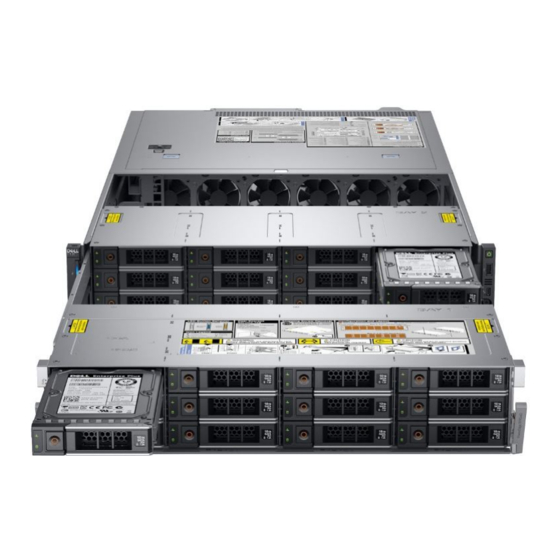
Dell EMC PowerEdge R740xd2 system overview The Dell EMC PowerEdge R740xd2 system is a 2U rack server that supports up to: • Two Intel Xeon Scalable Processor • 16 DIMM slots • Two redundant power supply units • 26 SAS, SATA, Nearline SAS hard drives or SSDs... -
Page 10: Control Panels
Figure 3. Right control panel view Power button USB 2.0-compliant port Micro USB 2.0-compliant port for iDRAC Direct iDRAC LED indicator NOTE: For more information on the ports, see the ports and connectors specifications section. Dell EMC PowerEdge R740xd2 system overview... -
Page 11: Rear View Of The System
Power supply unit (PSU 1) Information tag Power supply unit (PSU 2) LOM ethernet port (2) Ethernet port (Gb1) Ethernet port (Gb2) USB 3.0 port (2) iDRAC9 dedicated network port VGA port System identification button Dell EMC PowerEdge R740xd2 system overview... - Page 12 Power supply unit (PSU 1) Information tag Power supply unit (PSU 2) LOM ethernet port (2) Ethernet port (Gb1) Ethernet port (Gb2) USB 3.0 port (2) iDRAC9 dedicated network port VGA port System identification button Dell EMC PowerEdge R740xd2 system overview...
-
Page 13: Inside The System
Figure 8. Inside the system with butterfly riser Drive bay 1 Drive bay 2 Fans (6) Memory module Processor and heatsink module 1 Processor and heatsink module 2 System board LOM riser card Internal PERC riser Air shroud Butterfly riser Dell EMC PowerEdge R740xd2 system overview... -
Page 14: Locating The Information Tag Of Your System
Alternatively, the information may be on the Mini Enterprise Service Tag (MEST) label on the chassis, on the rear of the system. This information is used by Dell to route support calls to the appropriate personnel. Dell EMC PowerEdge R740xd2 system overview... - Page 15 Figure 10. Locating the information tag of your system Information tag (Top view) iDRAC MAC address and iDRAC secure password label Express Service Tag QRL label Information tag (back view) Dell EMC PowerEdge R740xd2 system overview...
-
Page 16: System Information Label
System Information Label Figure 11. PowerEdge R740xd2 – Service information Dell EMC PowerEdge R740xd2 system overview... - Page 17 Figure 12. Memory information Figure 13. OCP installation Figure 14. Riser installation Figure 15. Rear drive cage installation Dell EMC PowerEdge R740xd2 system overview...
- Page 18 Figure 16. Drive Bays Operation Figure 17. Drive configuration and layout Figure 18. System LED indicator and Express Service Tag Dell EMC PowerEdge R740xd2 system overview...
-
Page 19: Initial System Setup And Configuration
Initial system setup and configuration Setting up your system Perform the following steps to set up your system: Unpack the system. Remove the shipping screws from the sides of the system, before installing it in the rack. CAUTION: Do not attempt to lift the system by yourself to avoid potential injury. Do not apply uneven force to either end of the system to prevent the chassis from distorting or bending. -
Page 20: Log In To Idrac
Ensure that you change the default user name and password after setting up the iDRAC IP address. NOTE: The Intel Quick Assist Technology (QAT) on the Dell EMC PowerEdge R740xd2 is supported with chipset integration and is enabled through an optional license. The license files are enabled on the sleds through iDRAC. -
Page 21: Downloading Drivers And Firmware
Using iDRAC virtual media Dell.com/idracmanuals Downloading drivers and firmware Dell EMC recommends that you download and install the latest BIOS, drivers, and systems management firmware on your system. Prerequisite Ensure that you clear the web browser cache before downloading the drivers and firmware. -
Page 22: Pre-Operating System Management Applications
Pre-operating system management applications You can manage basic settings and features of a system without booting to the operating system by using the system firmware. Topics: • Options to manage the pre-operating system applications • System Setup • Dell Lifecycle Controller •... -
Page 23: System Setup Details
System Setup details The System Setup Main Menu screen details are explained as follows: Option Description System BIOS Enables you to configure BIOS settings. iDRAC Settings Enables you to configure the iDRAC settings. The iDRAC settings utility is an interface to set up and configure the iDRAC parameters by using UEFI (Unified Extensible Firmware Interface). - Page 24 Option Description to RAID mode. You might also need to change the Boot Mode setting to UEFI. Otherwise, you should set this field to Non-RAID mode. Boot Settings Specifies options to specify the Boot mode (BIOS or UEFI). Enables you to modify UEFI and BIOS boot settings. Network Settings Specifies options to manage the UEFI network settings and boot protocols.
- Page 25 Option Description System Specifies the current version of the Management Engine firmware. Management Engine Version System Service Tag Specifies the system Service Tag. System Specifies the name of the system manufacturer. Manufacturer System Specifies the contact information of the system manufacturer. Manufacturer Contact Information...
- Page 26 Option Description System Memory Specifies whether the system memory tests are run during system boot. Options are Enabled and Disabled. This Testing option is set to Disabled by default. Memory Operating Specifies the memory operating mode. The options available are Optimizer Mode, Single Rank Spare Mode, Multi Mode Rank Spare Mode, and Mirror Mode.
- Page 27 Option Description For best performance, you should select Maximum data rate. Any reduction in the communication link frequency affects the performance of non-local memory accesses and cache coherency traffic. In addition, it can slow access to non-local I/O devices from a particular CPU. However, if power saving considerations outweigh performance, you might want to reduce the frequency of the CPU communication links.
- Page 28 SATA Settings You can use the SATA Settings screen to view the SATA settings of SATA devices and enable SATA on your system. Viewing SATA Settings To view the SATA Settings screen, perform the following steps: Power on, or restart your system. Press F2 immediately after you see the following message: F2 = System Setup NOTE:...
- Page 29 Viewing Boot Settings To view the Boot Settings screen, perform the following steps: Power on, or restart your system. Press F2 immediately after you see the following message: F2 = System Setup NOTE: If your operating system begins to load before you press F2, wait for the system to finish booting, and then restart your system and try again.
- Page 30 • UEFI boot mode (the default), is an enhanced 64-bit boot interface. If you have configured your system to boot to UEFI mode, it replaces the system BIOS. From the System Setup Main Menu, click Boot Settings, and select Boot Mode. Select the UEFI boot mode you want the system to boot into.
- Page 31 Network Settings screen details The Network Settings screen details are explained as follows: Option Description PXE Device n (n = 1 Enables or disables the device. When enabled, a UEFI PXE boot option is created for the device. to 4) PXE Device n Enables you to control the configuration of the PXE device.
- Page 32 Integrated Devices You can use the Integrated Devices screen to view and configure the settings of all integrated devices including the video controller, integrated RAID controller, and the USB ports. Viewing Integrated Devices To view the Integrated Devices screen, perform the following steps: Power on, or restart your system.
- Page 33 Option Description NOTE: When there are multiple add-in graphic cards installed in the system, the first card discovered during PCI enumeration is selected as the primary video. You might have to re-arrange the cards in the slots in order to control which card is the primary video. Current State of Displays the current state of the embedded video controller.
- Page 34 Option Description Option Description Enables or disables or only the boot driver is disabled Slot 5 for the PCIe slot 5. This option is set to Enabled by default. Enables or disables or only the boot driver is disabled Slot 6 for the PCIe slot 6.
- Page 35 Serial Communication details The Serial Communication screen details are explained as follows: Option Description Serial Selects serial communication devices (Serial Device 1 and Serial Device 2) in BIOS. BIOS console redirection can Communication also be enabled, and the port address can be specified. This option is set to Auto by default. Serial Port Address Enables you to set the port address for serial devices.
- Page 36 System Profile Settings details The System Profile Settings screen details are explained as follows: Option Description System Profile Sets the system profile. If you set the System Profile option to a mode other than Custom, the BIOS automatically sets the rest of the options. You can only change the rest of the options if the mode is set to Custom.This option is set to Performance Per Watt Optimized (DAPC) by default.
- Page 37 Option Description PCI ASPM L1 Link Enables or disables the PCI ASPM L1 Link Power Management. This option is set to Enabled by default. Power Management System Security You can use the System Security screen to perform specific functions such as setting the system password, setup password and disabling the power button.
- Page 38 Option Description Deactivate, the TPM is disabled and deactivated. When set to Clear, all the contents of the TPM are cleared. This option is set to None by default. When TPM 2.0 is installed, the TPM Security option is set to On or Off. This option is set to Off by default. TPM 2.0 security information TPM Information Changes the operational state of the TPM.
- Page 39 Option Description Options Description User Mode In User Mode, PK must be installed, and BIOS performs signature verification on programmatic attempts to update policy objects. The BIOS allows unauthenticated programmatic transitions between modes. Audit Mode In Audit mode, PK is not present. The BIOS does not authenticate programmatic updates to the policy objects, and transitions between modes.
- Page 40 Reenter the setup password, and click OK. Press Esc to return to the System BIOS screen. Press Esc again. A message prompts you to save the changes. NOTE: Password protection does not take effect until the system reboots. Using your system password to secure the system About this task If you have assigned a setup password, the system accepts your setup password as an alternate system password.
- Page 41 Even after you turn off and restart the system, the error message is displayed until the correct password is typed. The following options are exceptions: • If System Password is not set to Enabled and is not locked through the Password Status option, you can assign a system password. For more information, see the System Security Settings screen section.
- Page 42 Option Description When set to Enabled, BIOS boots to the device specified in Redundant OS Location. When set to Disabled, BIOS preserves the current boot list settings. This option is set to Enabled by default. Miscellaneous Settings You can use the Miscellaneous Settings screen to perform specific functions such as updating the asset tag and changing the system date and time.
-
Page 43: Idrac Settings Utility
iDRAC Settings utility The iDRAC settings utility is an interface to set up and configure the iDRAC parameters by using UEFI. You can enable or disable various iDRAC parameters by using the iDRAC settings utility. NOTE: Accessing some of the features on the iDRAC settings utility needs the iDRAC Enterprise License upgrade. For more information about using iDRAC, see Dell Integrated Dell Remote Access Controller User's Guide at Dell.com/poweredgemanuals. -
Page 44: Boot Manager Main Menu
If your operating system begins to load before you press F11, allow the system to complete the booting, and then restart your system and try again. Boot Manager main menu Menu item Description Continue Normal The system attempts to boot to devices starting with the first item in the boot order. If the boot attempt fails, the Boot system continues with the next item in the boot order until the boot is successful or no more boot options are found. -
Page 45: Installing And Removing System Components
Installing and removing system components Safety instructions WARNING: Do not attempt to lift the system by yourself to avoid potential injury. Do not apply uneven force to either end of the system to prevent the chassis from distorting or bending. Keep the system parallel to the ground when lifting and moving it. WARNING: Opening or removing the system cover while the system is powered on may expose you to a risk of electric shock. -
Page 46: Recommended Tools
Recommended tools You need the following tools to perform the removal and installation procedures: • Key to the bezel lock The key is required only if your system includes a bezel. • Phillips #1 screwdriver • Phillips #2 screwdriver • Torx #T15 screwdriver •... -
Page 47: Installing The Front Bezel
Figure 19. Removing the front bezel Next step Replace the front bezel. Installing the front bezel Prerequisites Follow the safety guidelines listed in Safety instruction. Locate and remove the bezel key. NOTE: The bezel key is part of the front bezel package. Steps Align and insert the tabs on the right end of the bezel into the slots on the system. -
Page 48: System Cover
Figure 20. Installing the front bezel System cover Removing the system cover Prerequisites Follow the safety guidelines listed in Safety instructions. Power off the system and all attached peripherals. Disconnect the system from the electrical outlet, and disconnect the peripherals. Open the drive bays, remove drives, and then... -
Page 49: Installing The System Cover
Figure 21. Removing the system cover Installing the system cover Prerequisites Follow the safety guidelines listed in Safety instructions. Power off the system and all attached peripherals. Disconnect the system from the electrical outlet, and disconnect the peripherals. Ensure that all internal cables are routed correctly and connected, and no tools or extra parts are left inside the system. Open the drive bays, remove drives, and then... -
Page 50: Air Shroud
Figure 22. Installing system cover Next steps Close the drive bays. Place the system into the rack. For more information, see the Rail Installation Guide available at www.dell.com/poweredgemanuals. Open the drive bays, install drives, and then close the drive bays. Install the power supply units. - Page 51 If installed, remove the butterfly riser. Step Lift the air shroud away from the system. Figure 23. Removing air shroud Installing and removing system components...
-
Page 52: Installing The Air Shroud
Figure 24. Removing air shroud for system with rear drive configuration Next step Replace the air shroud. Installing the air shroud Prerequisites Follow the safety guidelines listed in Safety instructions. Power off the system and all attached peripherals. Disconnect the system from the electrical outlet, and disconnect the peripherals. Ensure that all internal cables are routed correctly and connected, and no tools or extra parts are left inside the system. - Page 53 Figure 25. Installing air shroud Installing and removing system components...
-
Page 54: Internal Perc Riser
Figure 26. Installing air shroud for system with the rear drive configuration Next steps If removed, install the butterfly riser. Install the system cover. Place the system into the rack. For more information, see the Rail Installation Guide available at www.dell.com/poweredgemanuals. Open the drive bays, install drives, and then... - Page 55 Open the cable guiding latch for easy access. Steps Lower the plunger and holding the blue touch points, lift the internal PERC riser out of the system. Figure 27. Removing internal PERC riser Turn over the internal riser so that the PERC card is facing up. Using a Phillips #2 screwdriver, loosen the screws from the cable connector and disconnect the cable connected to the internal PERC card.
-
Page 56: Installing The Internal Perc Riser
Figure 28. Disconnecting the cable from internal PERC card Next step Replace the internal PERC riser. Installing the internal PERC riser Prerequisites Follow the safety guidelines listed in Safety instructions. Power off the system and all attached peripherals. Disconnect the system from the electrical outlet, and disconnect the peripherals. Ensure that all internal cables are routed correctly and connected, and no tools or extra parts are left inside the system. - Page 57 Figure 29. Connecting the cable to internal PERC riser Turn over the internal PERC riser and align the internal PERC riser to the PCI slot by holding the blue touch points, and press until fully seated. Lift the plunger to lock the riser in place. Installing and removing system components...
-
Page 58: Removing The Perc Card From The Internal Perc Riser
Figure 30. Installing internal PERC riser Next steps Connect the cables to the backplane and then route the cables to the cable guiding latch and close the latch. If removed, install the rear drive cage. Install the air shroud. Install the system cover. -
Page 59: Installing Perc Card Into The Internal Perc Riser
Steps Disconnect the battery cable connected to the PERC card. Pull the PERC card out of the connector on the internal PERC riser. Figure 31. Removing the PERC card from the internal PERC riser Next step Replace the PERC card into the PERC riser. Installing PERC card into the internal PERC riser Prerequisites Follow the safety guidelines listed in... - Page 60 Remove the internal PERC riser. Steps Align the PERC card to the guiding pins on the internal PERC riser and push the card in. Route the battery cable around the riser and connect to the PERC card. Figure 32. Installing the PERC card into internal PERC riser Next steps Install the internal PERC riser If removed,...
-
Page 61: Cooling Fans
Cooling fans Removing the cooling fan Prerequisites Follow the safety guidelines listed in Safety instructions. Power off the system and all attached peripherals. Disconnect the system from the electrical outlet, and disconnect the peripherals. Open the drive bays, remove drives, and then close the drive bays. - Page 62 Figure 33. Removing cooling fan Installing and removing system components...
-
Page 63: Installing Cooling Fan
Figure 34. Disconnecting fan 1 cable from PIB connector Next step Replace the cooling fans. Installing cooling fan Prerequisites Follow the safety guidelines listed in Safety instructions. Power off the system and all attached peripherals. Disconnect the system from the electrical outlet, and disconnect the peripherals. Ensure that all internal cables are routed correctly and connected, and no tools or extra parts are left inside the system. - Page 64 Figure 35. Installing cooling fan Figure 36. Connecting fan 1 cable to PIB connector Installing and removing system components...
-
Page 65: Intrusion Switch
Next steps Install the internal PERC riser. Install the air shroud. Install the system cover. Place the system into the rack. For more information, see the Rail Installation Guide available at www.dell.com/poweredgemanuals. Open the drive bays, install drives, and then close the drive bays. -
Page 66: Installing The Intrusion Switch
Figure 37. Removing the intrusion switch Next step Replace the intrusion switch. Installing the intrusion switch Prerequisites Follow the safety guidelines listed in Safety instructions. Power off the system and all attached peripherals. Disconnect the system from the electrical outlet, and disconnect the peripherals. Ensure that all internal cables are routed correctly and connected, and no tools or extra parts are left inside the system. -
Page 67: Drive Bay
Figure 38. Installing the intrusion switch Connect the intrusion switch cable to the connector on the system board. NOTE: Route the cable properly when you replace it to prevent the cable from being pinched or crimped. Next steps Install the internal PERC riser. -
Page 68: Closing The Drive Bays
Steps If locked, unlock the drive bay lock located above the left release latch, by pushing it up. Open the release latches of drive bay 1 and pull the drive bays out. Figure 39. Opening the drive bays Next steps If installed, remove a drive blank install a drive... -
Page 69: Drives
Figure 40. Closing drive bays If required, lock the drive bay lock located above left release latch, by pushing it down. Next step If removed, install front bezel. Drives Removing a drive blank Prerequisites Follow the safety guidelines listed in Safety instructions. -
Page 70: Installing A Drive Blank
Figure 41. Removing a drive blank Next step Replace a drive blank. Installing a drive blank Prerequisites Follow the safety guidelines listed in Safety instructions. If installed, remove the front bezel. CAUTION: To maintain proper system cooling, drive blanks must be installed in all empty drive slots. CAUTION: Mixing drive blanks from previous generations of PowerEdge servers is not supported. -
Page 71: Installing A Drive Carrier
If installed, remove the front bezel. Using the management software, prepare the drive for removal. If the drive is online, the green activity or fault indicator flashes while the drive is turning off. When the drive indicators are off, the drive is ready for removal. -
Page 72: Removing The Drive From The Drive Carrier
CAUTION: When installing a drive, ensure that the adjacent drives are installed correctly. Inserting a drive carrier and attempting to lock its handle next to a incorrectly installed carrier can damage the incorrectly installed carrier's shield spring, making it unusable. CAUTION: To prevent data loss, ensure that your operating system supports hot-swap drive installation. -
Page 73: Installing A Drive Into The Drive Carrier
Figure 45. Removing the drive from the drive carrier Next step If applicable, install a drive into the drive carrier. Installing a drive into the drive carrier Prerequisites CAUTION: Mixing drive carriers from other generations of PowerEdge servers is not supported. NOTE: When installing a drive into the drive carrier, ensure that the screws are torqued to 4 inch-pounds. -
Page 74: Removing A 2.5-Inch Drive From A 3.5-Inch Drive Adapter
Figure 46. Installing a drive into the drive carrier Next step Install the drive carrier. Removing a 2.5-inch drive from a 3.5-inch drive adapter Prerequisite NOTE: A 2.5-inch drive is installed in a 3.5-inch drive adapter, which is then installed in the 3.5-inch drive carrier. Steps Using a Phillips #2 screwdriver, remove the screws from the side of the 3.5-inch drive adapter. -
Page 75: Installing A 2.5-Inch Drive Into A 3.5-Inch Drive Adapter
Figure 47. Removing a 2.5 inch drive from a 3.5-inch drive adapter Next step Replace a 2.5-inch drive into a 3.5-inch drive adapter. Installing a 2.5-inch drive into a 3.5-inch drive adapter Prerequisites Follow the safety guidelines listed in Safety instructions Remove the drive carrier. -
Page 76: Removing A 3.5-Inch Drive Adapter From A 3.5-Inch Drive Carrier
Figure 48. Installing a 2.5-inch drive into a 3.5-inch drive adapter Removing a 3.5-inch drive adapter from a 3.5-inch drive carrier Prerequisite Follow the safety guidelines listed in Safety instructions. Steps Using a Phillips #1 screwdriver, remove the screws from the rails on the drive carrier. Lift the 3.5-inch drive adapter out of the 3.5-inch drive carrier. -
Page 77: Installing A 3.5-Inch Drive Adapter Into The 3.5-Inch Drive Carrier
Figure 49. Removing a 3.5-inch drive adapter from a 3.5-inch drive carrier Next step Install the 3.5-inch drive adapter into the 3.5-inch drive carrier. Installing a 3.5-inch drive adapter into the 3.5-inch drive carrier Prerequisites Follow the safety guidelines listed in Safety instructions. -
Page 78: Drive Backplane Bracket
Figure 50. Installing a 3.5-inch drive adapter into the 3.5-inch drive carrier Next steps Install the 3.5-inch drive carrier into the system. If removed, install the front bezel. Drive backplane bracket Removing the drive bay 1 backplane bracket Prerequisites NOTE: Ensure that the drive bay 1 and 2 is in open position to access the backplane bracket. -
Page 79: Installing The Drive Bay 1 Backplane Bracket
Figure 51. Removing bay 1 backplane bracket Next step Replace the drive bay 1 backplane bracket. Installing the drive bay 1 backplane bracket Prerequisites Follow the safety guidelines listed in Safety instructions. Follow the procedure listed in Before working inside your system. If installed, remove the front bezel. -
Page 80: Removing The Drive Bay 2 Backplane Brackets
Figure 52. Installing bay 1 backplane bracket Next steps Install all the drives. Close the drive bays. If removed, install the front bezel. Follow the procedure listed in After working inside your system. Removing the drive bay 2 backplane brackets Prerequisites Follow the safety guidelines listed in Safety... -
Page 81: Installing The Drive Bay 2 Backplane Brackets
Lift the right bracket away from the system and move the left bracket away from the drive bay. Figure 53. Removing bay 2 backplane brackets Next step Replace the drive bay 2 backplane brackets. Installing the drive bay 2 backplane brackets Prerequisites Follow the safety guidelines listed in Safety... -
Page 82: Bay Intrusion Switch
Figure 54. Installing bay 2 backplane brackets Next steps Place the system into the rack. For more information, see the Rail Installation Guide available at www.dell.com/poweredgemanuals. Open the drive bays, install drives, and then close the drive bays. Install the power supply units. -
Page 83: Installing Bay Intrusion Switch
Figure 55. Removing the bay intrusion switch Next step Replace the bay intrusion switch. Installing bay intrusion switch Prerequisites Follow the safety guidelines listed in Safety instructions. Follow the procedure listed in Before working inside your system. If installed, remove the front bezel. -
Page 84: Rear Drive Cage
Figure 56. Installing the bay intrusion switch Next steps Install the drive bay 1 bracket. Close the drive bays. If removed, install the front bezel. Follow the procedure listed in After working inside your system. Rear drive cage Removing the rear drive cage Prerequisites Follow the safety guidelines listed in Safety... -
Page 85: Installing The Rear Drive Cage
Steps Using Phillips #2 screwdriver, loosen the screws that secure the drive cage to the system. Disengage the rear drive cage from the chassis by pushing it towards the front of the system and lift the drive cage away from the system. -
Page 86: Drive Backplane
After working inside your system. Drive backplane Drive backplane guidelines Depending on your system configuration, the drive backplanes supported in PowerEdge R740xd2 are listed here: Table 5. Supported backplane options for PowerEdge R740xd2 system System Supported backplane options PowerEdge R740xd2 3.5-inch (x12) SAS/SATA/SSD backplane (front) -
Page 87: Removing The Drive Bay 1 Backplane
NOTE: The backplane for both drive bay 1 and bay 2 is identical. Figure 59. 12 x 3.5-inch drive backplane Power connector (J_BP_PWR1) SAS/SATA cable connector (BP SAS A1) SAS/SATA cable connector (BP SAS A2) Signal connector (J_BP_SIG1) SAS/SATA cable connector (BP SAS B0) SAS/SATA cable connector(BP SAS A0) Intrusion switch cable connector Figure 60. - Page 88 Remove the drive bay 1 bracket. Remove the bay intrusion switch. Disconnect all the cables from the backplane. Steps Using Phillips #2 screwdriver, remove all the screws securing the backplane. Figure 61. Removing the screws from the backplane Hold the backplane by the edges and remove it from the bay. Figure 62.
-
Page 89: Installing The Drive Bay 1 Backplane
Installing the drive bay 1 backplane Prerequisites Follow the safety guidelines listed in Safety instructions. NOTE: The procedure to install the backplane is similar for all backplane configurations. Follow the procedure listed in Before working inside your system. If installed, remove front bezel. -
Page 90: Removing The Drive Bay 2 Backplane
Close the drive bays. If removed, install front bezel. Follow the procedure listed in After working inside your system. Removing the drive bay 2 backplane Prerequisites CAUTION: Note the number of each drive and temporarily label them before you remove the drive so that you can replace them in the same location. -
Page 91: Installing The Drive Bay 2 Backplane
Figure 65. Removing bay 2 backplane Next step Replace the drive bay 2 backplane. Installing the drive bay 2 backplane Prerequisites Follow the safety guidelines listed in Safety instructions. Power off the system and all attached peripherals. Disconnect the system from the electrical outlet, and disconnect the peripherals. Ensure that all internal cables are routed correctly and connected, and no tools or extra parts are left inside the system. -
Page 92: Removing The Rear Drive Backplane
Figure 66. Installing bay 2 backplane Next steps Connect all the cables to the backplane. Install the drive bay 2 brackets. Close the drive bays. Place the system into the rack. For more information, see the Rail Installation Guide available at www.dell.com/poweredgemanuals. Open the drive bays, install drives, and then... -
Page 93: Installing The Rear Drive Backplane
Remove the system from the rack and place it on an ESD work bench. For more information, see the Rail Installation Guide available at www.dell.com/poweredgemanuals. Remove the drives from the rear drive cage. Disconnect all the cables from the backplane. Remove the rear drive cage. -
Page 94: Cable Routing
Remove the rear drive cage. Steps Use the hooks on the rear drive cage as guides to align the drive backplane. Lower the backplane into the rear drive cage until it is firmly seated. Using Phillips #2 screwdriver, tighten the screws to secure the backplane to the rear drive cage. Figure 68. - Page 95 Figure 69. Cable routing - System with 2 x 3.5-inch rear drive backplane connected to cable chain assembly Figure 70. Cable routing - System with 2 x 3.5-inch rear drive backplane connected to riser PERC Installing and removing system components...
-
Page 96: System Memory
Figure 71. Cable routing - System with 2 x 3.5-inch rear drive backplane connected to system board SATA port System memory System memory guidelines The PowerEdge systems support DDR4 Registered DIMMs (RDIMMs). System memory holds the instructions that are executed by the processor. - Page 97 Figure 72. System memory Memory channels are organized as follows: Table 7. Memory channels Processor Channel 0 Channel 1 Channel 2 Channel 3 Channel 4 Channel 5 Processor 1 Slots A1 and A7 Slots A2 and A8 Slots A3 Slots A4 and A9 Slots A5 and A10 Slots A6 Processor 2...
-
Page 98: General Memory Module Installation Guidelines
General memory module installation guidelines To ensure optimal performance of your system, observe the following general guidelines when configuring your system memory. If your system's memory configurations fail to observe these guidelines, your system might not boot, stop responding during memory configuration, or operate with reduced memory. - Page 99 Table 9. Memory operating modes Memory Operating Mode Description Optimizer Mode The Optimizer Mode if enabled, the DRAM controllers operate independently in the 64-bit mode and provide optimized memory performance. Mirror Mode The Mirror Mode if enabled, the system maintains two identical copies of data in memory, and the total available system memory is one half of the total installed physical memory.
- Page 100 NOTE: Processor 1 and processor 2 population should match. Table 10. Memory population rules Processor Configuration Memory population Memory population information Single processor Optimizer (Independent channel) 1, 2, 3, 4, 5, 6, 7, 8, 9, 10 • Populate in this order, odd amount population order allowed.
-
Page 101: Removing A Memory Module
Processor Configuration Memory population Memory population information – For 14 DIMMs: A1, A2, A4, A5, A7, A8, A9, A10, B1, B2, B3, B4, B5, B6 Mirroring population order A{1, 2, 3, 4, 5, 6}, B{1, 2, 3, 4, 5, Mirroring is supported with 6 DIMM slots per processor. -
Page 102: Installing A Memory Module
Figure 73. Removing a memory module Next step Replace the memory module. Installing a memory module Prerequisites Follow the safety guidelines listed in Safety instructions. Power off the system and all attached peripherals. Disconnect the system from the electrical outlet, and disconnect the peripherals. Ensure that all internal cables are routed correctly and connected, and no tools or extra parts are left inside the system. -
Page 103: Processor And Heat Sink
Figure 74. Installing a memory module Next steps Install the air shroud. Install the system cover. Place the system into the rack. For more information, see the Rail Installation Guide available at www.dell.com/poweredgemanuals. Open the drive bays, install drives, and then close the drive bays. -
Page 104: Removing The Processor
Remove the air shroud. If installed, remove the rear drive cage. If installed, remove the risers. Steps Using a Torx #T30 screwdriver, loosen the screws on the heat sink in the order below: Loosen the first screw three turns. b Loosen the second screw completely. Return to the first screw and loosen it completely. - Page 105 Remove the power supply units. Remove the system from the rack and place it on an ESD work bench. For more information, see the Rail Installation Guide available at www.dell.com/poweredgemanuals. Remove the system cover. Remove the air shroud. If installed, remove the rear drive cage.
-
Page 106: Installing The Processor
Figure 77. Removing the processor bracket Next step Replace the processor into a processor and heat sink module. Installing the processor Prerequisites Follow the safety guidelines listed in Safety instructions. Power off the system and all attached peripherals. Disconnect the system from the electrical outlet, and disconnect the peripherals. Ensure that all internal cables are routed correctly and connected, and no tools or extra parts are left inside the system. - Page 107 Figure 78. Installing the processor bracket If you are using an existing heat sink, remove the thermal grease from the heat sink by using a clean lint-free cloth. Use the thermal grease syringe included with your processor kit to apply the grease in a quadrilateral design on the top of the processor.
- Page 108 Place the heat sink on the processor and push down on the base of the heat sink until the bracket locks onto the heat sink. NOTE: • Ensure that the two guide pin holes on the bracket match the guide holes on the heat sink. •...
-
Page 109: Installing A Processor And Heat Sink Module
Installing a processor and heat sink module Prerequisites CAUTION: Never remove the heat sink from a processor unless you intend to replace the processor. The heat sink is necessary to maintain proper thermal conditions. Follow the safety guidelines listed in Safety instructions. -
Page 110: Expansion Cards And Expansion Card Risers
Troubleshooting expansion cards section in system from turning on. However, if a F1/F2 pause occurs with an error message, see Dell EMC PowerEdge Servers Troubleshooting Guide at Dell.com/poweredgemanuals. Expansion card installation guidelines The following table provides guidelines for installing expansion cards to ensure proper cooling and mechanical fit. The expansion cards with the highest priority should be installed first using the slot priority indicated. - Page 111 Table 11. Riser configurations: System without riser - Processor 1 Card Type Slot Priority Maximum number of cards LOM riser ; 2x1G BCM5720L (FXN) PCIe SSD PCIe Card (Samsung) Card (Broadcom/INTEL/Mellanox/ Solarflare/QLOGIC) BOSS M.2 (SATA) (Dell) 1G Card,Network (Broadcom/INTEL) 6, 5 Internal PERC , PERC9/9.14G (FXN) Integrated Slot External PERC PERC 9/9.14G/10...
- Page 112 Table 14. Riser configurations: Low profile (Riser 1) + Low profile (Riser 2) - Processor 1 and 2 Card type Slot priority Maximum number of cards LOM riser ; 2x1G BCM5720L LOM riser ; 2x10G BCM57416 (BASeT/SFP LOM riser: Broadcom 25G card, 930PP PCIe SSD PCIe Card (Samsung) 3, 2 Cards (Broadcom/INTEL/Mellanox/...
-
Page 113: Removing Expansion Card From The System Board
Table 16. Riser configurations: Butterfly riser + 3 x low profile - Processor 1 and 2 Card type Slot priority Maximum number of cards LOM riser ; 2x1G BCM5720L (FXN) LOM riser ; 2x10G BCM57416 (BASeT/SFP +) (FXN) LOM riser: Broadcom 25G card, 930PP RAID - PERC 9/9.14G/10 (External) 4, 3, 2, 5 Full Height (FH) Card Network, (Broadcom/... - Page 114 Figure 82. Removing expansion card from system board If the expansion card is not going to be replaced, install a filler bracket by performing the following steps: Align the filler bracket with the slot on the system. b Push the filler bracket downward until firmly seated. Close the retention latch by pressing the latch down until the latch snaps into place.
-
Page 115: Removing Expansion Card From The Expansion Card Riser
Figure 83. Installing the filler bracket NOTE: Filler brackets must be installed over empty expansion card slots to maintain FCC certification of the system. The brackets also keep dust out of the system and aid in proper cooling and airflow inside the system. Next step Replace the expansion card on the system board. - Page 116 Steps Open the expansion card retention latch. Hold the expansion card by its edges, and pull the card away from the expansion card connector on the riser. Figure 84. Removing expansion card from low profile riser Figure 85. Removing expansion card from full height X1 riser Installing and removing system components...
- Page 117 Figure 86. Removing expansion card from butterfly riser If the expansion card is not going to be replaced, install a filler bracket. Figure 87. Installing filler bracket for low profile riser Installing and removing system components...
- Page 118 Figure 88. Installing filler bracket for full height X1 riser Figure 89. Installing filler bracket for butterfly riser Next steps Replace expansion card into the expansion card riser. Installing and removing system components...
-
Page 119: Installing Expansion Card Into The Expansion Card Riser
If you are removing the card permanently, install a metal filler bracket over the empty expansion slot opening and push the expansion card latch. NOTE: You must install a filler bracket over an empty expansion card slot to maintain Federal Communications Commission (FCC) certification of the system. - Page 120 Figure 90. Removing filler bracket for low profile riser Figure 91. Removing filler bracket for full height X1 riser Installing and removing system components...
- Page 121 Figure 92. Removing filler bracket for butterfly riser Hold the card by its edges, and align the card edge connector with the expansion card connector on the riser. Insert the card edge connector firmly into the expansion card connector until the card is fully seated. Close the expansion card retention latch.
- Page 122 Figure 93. Installing expansion card into low profile riser Figure 94. Installing expansion card into full height X1 riser Installing and removing system components...
-
Page 123: Installing Expansion Card On The System Board
Figure 95. Installing expansion card into butterfly riser Next steps Install the expansion card riser in the system. If applicable, connect the cables to the expansion card. If removed, install the rear drive cage. Install air shroud. Install the system cover. - Page 124 Remove the system cover. Remove the air shroud. If installed, remove the rear drive cage. If installed, remove the expansion card risers. Steps Unpack the expansion card and prepare it for installation. For instructions, see the documentation accompanying the card. If you are installing a new card, remove the filler bracket.
-
Page 125: Removing An Expansion Card Riser
Figure 97. Installing expansion card on system board Next steps Connect the required cables to the expansion card. If removed, install the rear drive cage. Install air shroud. Install the system cover. Place the system into the rack. For more information, see the Rail Installation Guide available at www.dell.com/poweredgemanuals. Open the drive bays, install drives, and then... - Page 126 If installed, remove the rear drive cage. Disconnect any cables connected to the expansion card. Step Hold the touch points and lift the expansion card riser from the connector on the system board. Figure 98. Removing right low profile riser Installing and removing system components...
- Page 127 Figure 99. Removing left low profile riser Figure 100. Removing full height X1 riser Installing and removing system components...
-
Page 128: Installing An Expansion Card Riser
NOTE: For butterfly riser, loosen the captive screw and holding the touch points lift the riser away from the system. Figure 101. Removing butterfly riser Next step Install the expansion card riser. Installing an expansion card riser Prerequisites Follow the safety guidelines listed in Safety instructions. - Page 129 Lower the expansion card riser into place until the expansion card riser connector is fully seated in the connector. Figure 102. Installing right low profile riser Installing and removing system components...
- Page 130 Figure 103. Installing left low profile riser Figure 104. Installing full height X1 riser Installing and removing system components...
-
Page 131: M.2 Ssd Module
NOTE: For butterfly riser, tighten the captive screw to firmly hold the riser to the system board. Figure 105. Installing butterfly riser Next steps If removed, install the rear drive cage. Install the air shroud. Install the system cover. Place the system into the rack. For more information, see the Rail Installation Guide available at www.dell.com/poweredgemanuals. Open the drive bays, install drives, and then... -
Page 132: Installing The M.2 Ssd Module
Remove the power supply units. Remove the system from the rack and place it on an ESD work bench. For more information, see the Rail Installation Guide available at www.dell.com/poweredgemanuals. Remove the system cover. Remove the air shroud. If installed, remove the rear drive cage. -
Page 133: Optional Idsdm / Vflash Module
Remove the system cover. Remove the air shroud. Remove the BOSS card. NOTE: The procedure to remove the BOSS card is similar to the removing an expansion card. Steps Insert the M.2 SSD module at an angle into the BOSS card connector. Push the other end of the M.2 SSD module until it rests on the stand off on the BOSS card. -
Page 134: Removing The Idsdm/Vflash Module
Removing the IDSDM/vFlash module Prerequisites Follow the safety guidelines listed in Safety instructions. Power off the system and all attached peripherals. Disconnect the system from the electrical outlet, and disconnect the peripherals. Open the drive bays, remove drives, and then close the drive bays. -
Page 135: Removing The Microsd Card
Ensure that all internal cables are routed correctly and connected, and no tools or extra parts are left inside the system. Open the drive bays, remove drives, and then close the drive bays. Remove the power supply units. Remove the system from the rack and place it on an ESD work bench. For more information, see the Rail Installation Guide available at www.dell.com/poweredgemanuals. -
Page 136: Installing The Microsd Card
Remove the power supply units. Remove the system from the rack and place it on an ESD work bench. For more information, see the Rail Installation Guide available at www.dell.com/poweredgemanuals. Remove the system cover. Remove the air shroud. Remove the IDSDM or vFlash module. Steps Locate the MicroSD card slot on the IDSDM/vFlash module, and press the card to partially release it from the slot. - Page 137 Remove the system cover. Remove the air shroud. Remove the IDSDM or vFlash module. NOTE: To use an MicroSD card with your system, ensure that the Internal SD Card Port is enabled in System Setup. NOTE: If reinstalling, ensure that you install the MicroSD cards into the same slots based on the labels you had marked on the cards during removal.
-
Page 138: Lom Riser Card
LOM riser card Removing the LOM riser card Prerequisites Follow the safety guidelines listed in Safety instructions. Power off the system and all attached peripherals. Disconnect the system from the electrical outlet, and disconnect the peripherals. Open the drive bays, remove drives, and then close the drive bays. -
Page 139: Installing The Lom Riser Card
Installing the LOM riser card Prerequisites Follow the safety guidelines listed in Safety instructions. Power off the system and all attached peripherals. Disconnect the system from the electrical outlet, and disconnect the peripherals. Ensure that all internal cables are routed correctly and connected, and no tools or extra parts are left inside the system. Open the drive bays, remove drives, and then... -
Page 140: System Battery
Install the air shroud. Install the system cover. Place the system into the rack. For more information, see the Rail Installation Guide available at www.dell.com/poweredgemanuals. Open the drive bays, install drives, and then close the drive bays. Install the power supply units. - Page 141 Figure 114. Removing the system battery To install a new system battery, hold the battery with the positive side facing up and slide it under the securing tabs. Press the battery into the connector until it snaps into place. Figure 115. Installing the system battery Next steps If removed, install the low profile or full height X1 expansion card...
-
Page 142: Optional Internal Usb Memory Key
Enter the correct time and date in the System Setup Time and Date fields. Exit the System Setup. Optional internal USB memory key NOTE: To locate the internal USB port on the system board, see the System board jumpers and connectors section. -
Page 143: Power Supply Units
Figure 117. Installing the internal USB memory key USB memory key USB port Next steps If removed, install the low profile expansion card riser. If removed, install the air shroud. Install the system cover. Place the system into the rack. For more information, see the Rail Installation Guide available at www.dell.com/poweredgemanuals. Open the drive bays, install drives, and then... -
Page 144: Removing A Power Supply Unit Blank
Removing a power supply unit blank Prerequisite Follow the safety guidelines listed in Safety instructions. Step If you are installing a second power supply unit, remove the power supply unit blank in the bay by pulling the blank outward. CAUTION: To ensure proper system cooling, the power supply unit blank must be installed in the second power supply unit bay in a non-redundant configuration. -
Page 145: Removing A Power Supply Unit
Figure 119. Installing a power supply unit blank Next step Follow the procedure listed in After working inside your system. Removing a power supply unit The procedure for removing AC and DC PSUs is identical. Prerequisites CAUTION: The system needs one power supply unit (PSU) for normal operation. On power-redundant systems, remove and replace only one PSU at a time in a system that is powered on. -
Page 146: Installing A Power Supply Unit
Installing a power supply unit The procedure for installing AC and DC PSUs is identical. Prerequisites Follow the safety guidelines listed in Safety instructions. Ensure that both the PSUs are of the same type and have the same maximum output power. NOTE: The maximum output power (shown in watts) is listed on the PSU label. -
Page 147: Installing Dc Power Supply Unit
CAUTION: The system needs one PSU for normal operation. On power-redundant systems, remove and replace only one PSU at a time in a system that is powered on. Follow the safety guidelines listed in Safety instructions. Disconnect the power wires from the power source and the connector from the PSU you intend to remove. Disconnect the safety ground wire. -
Page 148: Installing Power Interposer Board
Remove the system cover. Remove the air shroud. Disconnect all the cables from the power interposer board (PIB). CAUTION: To prevent damage to the power interposer board, you must remove the power supply module (s) from the system before removing the power interposer board. NOTE: Ensure that you note the routing of the cables as you remove them from the system board. -
Page 149: System Board
Remove the air shroud. Disconnect all the cables connected to the system board. Steps Press the blue release tab and align the slots on the PIB with the hooks on the PSU cage and slide it into place. Route the cables and connect it to the system board. Figure 123. - Page 150 CAUTION: Do not attempt to remove the TPM plug-in module from the system board. Once the TPM plug-in module is installed, it is cryptographically bound to that specific system board. Any attempt to remove an installed TPM plug-in module breaks the cryptographic binding, and it cannot be re-installed or installed on another system board.
- Page 151 Figure 124. System board screws Hold the system board holder, slightly lift the system board, and then slide it toward the front of the chassis. CAUTION: To prevent damage to the processor socket when replacing a faulty system board, ensure that you cover the processor socket with the processor dust cover.
-
Page 152: Installing The System Board
Figure 125. Removing the system board Next step Replace or install the system board. Installing the system board Prerequisites Follow the safety guidelines listed in Safety instructions. Power off the system and all attached peripherals. Disconnect the system from the electrical outlet, and disconnect the peripherals. Ensure that all internal cables are routed correctly and connected, and no tools or extra parts are left inside the system. - Page 153 LOM riser card Steps Unpack the new system board. CAUTION: Do not lift the system board by holding a memory module, processor, or other components. CAUTION: Take care not to damage the system identification button while placing the system board into the chassis. Holding the system board holder, push the system board toward the back of the system till it is seated.
- Page 154 NOTE: Ensure that the cables inside the system are routed along the chassis wall and secured using the cable securing bracket. Install the system cover. Place the system into the rack. For more information, see the Rail Installation Guide available at www.dell.com/poweredgemanuals. Open the drive bays, install drives, and then...
-
Page 155: Trusted Platform Module
Trusted Platform Module Upgrading the Trusted Platform Module Prerequisites Follow the safety guidelines listed Safety instructions. Power off the system and all attached peripherals. Disconnect the system from the electrical outlet, and disconnect the peripherals. Ensure that all internal cables are routed correctly and connected, and no tools or extra parts are left inside the system. Open the drive bays, remove drives, and then... -
Page 156: Initializing Tpm For Bitlocker Users
Figure 127. Installing the TPM Next steps If removed, install the risers. If removed, install the rear drive cage. Install the air shroud. Install the system cover. Place the system into the rack. For more information, see the Rail Installation Guide available at www.dell.com/poweredgemanuals. Open the drive bays, install drives, and then... -
Page 157: Initializing The Tpm 2.0 For Txt Users
Initializing the TPM 2.0 for TXT users While booting your system, press F2 to enter System Setup. On the System Setup Main Menu screen, click System BIOS > System Security Settings. From the TPM Security option, select On. Save the settings. Restart your system. - Page 158 Figure 128. Removing the support bar, cable chain top cover and disconnecting the bay 2 backplane bracket from the cable chain assembly. Loosen the captive screw for the cable chain side cover and disengage it from the guiding pins below and lift it away from the system. Slide the left side of the system, partially off the table, until the bottom screws for the cable chain base bracket are visible and remove the screws.
- Page 159 Figure 129. Removing screws for cable chain base bracket and cable chain side cover Slide drive bay 2 towards the rear of the system until the screws for the left and right white plastic rail stops are visible and remove them.
- Page 160 Figure 130. Removing the left and right rail white plastic rail stops Remove the screws connecting the cable chain rail to the chassis. Extend the drive bays all the way out of the bay area, until there is a gap to remove the cable chain rail. Lift the cable chain assembly out of the system.
-
Page 161: Installing The Cable Chain Assembly
Figure 131. Removing the cable chain assembly from the system Next step Replace the cable chain assembly. Installing the cable chain assembly Prerequisites Follow the safety guidelines listed in Safety instructions. Power off the system and all attached peripherals. Disconnect the system from the electrical outlet, and disconnect the peripherals. Ensure that all internal cables are routed correctly and connected, and no tools or extra parts are left inside the system. - Page 162 Memory modules for processor 1. PIB. Disconnect all cables connected to the cable chain assembly from the backplanes and the system board. Steps Place the cable chain assembly in the system and route the left control panel cable through the cable chain base bracket. Using a Phillips #1 screwdriver, replace the screws for the cable chain rail after aligning it to the chassis and align the cable chain assembly to the bottom screw holes.
- Page 163 Figure 133. Replacing the cable chain side cover and the bottom screws Replace the screws for the left and right white plastic rail stops. NOTE: Make sure the left control panel cable is routed through the cable chain base bracket and connect the cable connector to the system board connector.
- Page 164 Figure 134. Replacing the screws for the left and right white plastic rail stops Align the support bar to the chassis and replace all the screws. Align the bay 2 backplane bracket to the cable chain assembly and replace the screws. Align the cable chain top cover to the guiding pins and replace all the screws.
- Page 165 Figure 135. Replacing the support bar, cable chain top cover and connecting the bay 2 backplane bracket from the cable chain assembly. Next steps Replace the following: PIB. Memory modules for processor 1. Internal PERC card If installed, rear drive cage. Intrusion switch.
-
Page 166: Control Panel
Control panel Removing the left control panel Prerequisites Follow the safety guidelines listed in Safety instructions. Power off the system and all attached peripherals. Disconnect the system from the electrical outlet, and disconnect the peripherals. Open the drive bays, remove drives, and then close the drive bays. -
Page 167: Installing The Left Control Panel
Figure 136. Removing the left control panel Next step Replace the left control panel. Installing the left control panel Prerequisites Follow the safety guidelines listed in Safety instructions. Power off the system and all attached peripherals. Disconnect the system from the electrical outlet, and disconnect the peripherals. Ensure that all internal cables are routed correctly and connected, and no tools or extra parts are left inside the system. -
Page 168: Removing The Right Control Panel
Figure 137. Installing the left control panel Connect the control panel cable to the system board connector. Next steps Install the cable chain assembly. Close the drive bays. Place the system into the rack. For more information, see the Rail Installation Guide available at www.dell.com/poweredgemanuals. Install the power supply units. - Page 169 Remove the air shroud. Remove the internal PERC card. Disconnect all cables connected to the system board. Steps Open the blue release clip and disconnect the right control panel cable from the system board. Release the cable from the right rack ear cable clips and push the cable connector through the side of the fan cage. NOTE: Ensure that you note the routing of the cables as you remove them from the system board.
-
Page 170: Installing The Right Control Panel
Figure 139. Removing the right control panel Next step Replace the right control panel. Installing the right control panel Prerequisites Follow the safety guidelines listed in Safety instructions. Power off the system and all attached peripherals. Ensure that all internal cables are routed correctly and connected, and no tools or extra parts are left inside the system. Open the drive bays, remove drives, and then... - Page 171 Figure 140. Aligning the right control panel cable Extend bay 2 and pull the cable through the side of the bay. Route the cable through the right control panel cable clip and push the cable connector through the side of the fan cage. Connect the control panel cable to the connector on the system board and close the blue release clip.
- Page 172 Figure 141. Installing the right control panel Next steps Install the internal PERC card. Install the air shroud. Close the drive bays. Install the system cover. Place the system into the rack. For more information, see the Rail Installation Guide available at www.dell.com/poweredgemanuals. Install the power supply units.
-
Page 173: Jumpers And Connectors
Jumpers and connectors This topic provides specific information about the jumpers. It also provides some basic information about jumpers and switches and describes the connectors on the various boards in the system. Jumpers on the system board help to disable the system and setup passwords. - Page 174 Table 17. System board jumpers and connectors Item Connector Description FAN6 Fan6 connector FAN5 Fan5 connector FAN4 Fan4 connector CPU1 Processor socket 1 CPU1_PWR_CONN(P2) CPU1 power connector J_INTRU Intrusion switch connector FAN3 Fan3 connector FAN2 Fan2 connector J_BP_SIG1 Backplane signal connector 1 LFT_CP_CONN Left control panel connector RGT_CP_CONN...
-
Page 175: System Board Jumper Settings
System board jumper settings For information on resetting the password jumper to disable a password, see the Disabling a forgotten password section. Table 18. System board jumper settings Jumper Setting Description PWRD_EN The BIOS password feature is enabled. The BIOS password feature is disabled. iDRAC local access is unlocked at next AC power cycle. -
Page 176: Technical Specifications
Technical specifications The technical and environmental specifications of your system are outlined in this section. Topics: • Chassis dimensions • System weight • Processor specifications • Supported operating systems • PSU specifications • Cooling fans specifications • System battery specifications •... -
Page 177: Chassis Dimensions
Chassis dimensions Figure 143. Chassis dimensions Table 19. Dell EMC PowerEdge R740xd2 chassis dimensions With bezel: 35.93 482.0 mm 448.0 mm 86.8 mm 810.264 mm 844.826mm mm (1.41 inches) (18.9 inches) (17.63 inches) (3.41 inches) (31.9 inches) (33.260 inches) Without bezel: 22.0 mm (0.866 inches) -
Page 178: Processor Specifications
NOTE: For more information about the specific versions and additions, go to https://www.dell.com/support/home/Drivers/ SupportedOS/poweredge-r740xd2. PSU specifications The Dell EMC PowerEdge R740xd2 system supports up to two AC or DC power supply units (PSUs). Table 22. PSU specifications Class Heat Frequency... -
Page 179: Cooling Fans Specifications
The Dell EMC PowerEdge R740xd2 system supports CR 2032 3.0-V lithium coin cell system battery. PCIe Expansion card riser specifications The Dell EMC PowerEdge R740xd2 system supports up to three PCI express (PCIe) generation 3 expansion cards that can be installed on the system board and expansion card risers.. -
Page 180: Memory Specifications
Memory specifications The Dell EMC PowerEdge R740xd2 system supports 16 DDR4 registered DIMM (RDIMMs) slots. Supported memory bus frequencies are 1866 MT/s, 2133 MT/s, 2400 MT/s, and 2666 MT/s. Table 25. Memory specifications Single processor Dual processors DIMM type DIMM rank... -
Page 181: Ports And Connectors Specifications
Direct or a management port. NIC ports specifications The Dell EMC PowerEdge R740xd2 system supports up to two Network Interface Controller (NIC) ports on the back panel, which have two 1 Gbps configuration. NOTE:... -
Page 182: Video Specifications
Use Dell EMC branded microSD cards that are associated with the IDSDM or vFlash configured systems. Video specifications The Dell EMC PowerEdge R740xd2 system supports integrated Matrox G200eW3 graphics controller with 16 MB of video frame buffer. Table 30. Supported video resolution options... - Page 183 Temperature Specifications Maximum temperature gradient (operating and 20°C/h (36°F/h) storage) Table 32. Relative humidity specifications Relative humidity Specifications Storage 5% to 95% RH with 33°C (91°F) maximum dew point. Atmosphere must be noncondensing at all times. Operating 10% to 80% RH with 29°C (84.2°F) maximum dew point. Table 33.
-
Page 184: Standard Operating Temperature
Standard operating temperature Table 37. Standard operating temperature specifications Standard operating temperature Specifications Continuous operation (for altitude less than 950 m or 3117 10°C to 30°C (50°F to 86°F) with no direct sunlight on the equipment. Thermal restrictions • System must operate at temperature below 30°C. •... -
Page 185: Particulate And Gaseous Contamination Specifications
Table 39. Expansion cards thermal limitation Thermal Cooling Bus width Full height Cards Application Half height Cards Application Tier level Restriction Restriction (Configuration (Configuration Type / PCIe slot) Type / PCIe slot) Rear HDD Module QLOGIC 10G Dual Butterfly Riser Configuration / port BT, QLOGIC Configuration /... - Page 186 Particulate contamination Specifications NOTE: Air entering the data center must have MERV11 or MERV13 filtration. Conductive dust Air must be free of conductive dust, zinc whiskers, or other conductive particles. NOTE: This condition applies to data center and non-data center environments.
-
Page 187: System Diagnostics And Indicator Codes
System diagnostics and indicator codes The diagnostic indicators on the system front panel display system status during system startup. Topics: • System health and system ID indicator codes • iDRAC Direct LED indicator codes • NIC indicator codes • Power supply unit indicator codes •... -
Page 188: Idrac Direct Led Indicator Codes
Table 42. System health and system ID indicator codes System health and system ID indicator Condition code Solid blue Indicates that the system is turned on, system is healthy, and system ID mode is not active. Press the system health and system ID button to switch to system ID mode. Blinking blue Indicates that the system ID mode is active. -
Page 189: Power Supply Unit Indicator Codes
Table 44. NIC indicator codes Status Condition Link and activity indicators are off. The NIC is not connected to the network. Link indicator is green, and activity indicator is blinking The NIC is connected to a valid network at its maximum port speed, and green. - Page 190 Power indicator codes Condition CAUTION: If two PSUs are installed, both the PSUs must have the same type of label; for example, Extended Power Performance (EPP) label. Mixing PSUs from previous generations of PowerEdge servers is not supported, even if the PSUs have the same power rating. This results in a PSU mismatch condition or failure to power on the system.
-
Page 191: Drive Indicator Codes
Power indicator codes Condition CAUTION: If two PSUs are installed, both the PSUs must have the same type of label; for example, Extended Power Performance (EPP) label. Mixing PSUs from previous generations of PowerEdge servers is not supported, even if the PSUs have the same power rating. This results in a PSU mismatch condition, or failure to power on the system. -
Page 192: Using System Diagnostics
Table 47. Drive indicator codes Drive status indicator code Condition Flashes green twice per second Identifying drive or preparing for removal. Drive ready for removal. NOTE: The drive status indicator remains off until all drives are initialized after the system is turned on. Drives are not ready for removal during this time. - Page 193 Running the Embedded System Diagnostics from the Dell Lifecycle Controller As the system boots, press F10. Select Hardware Diagnostics → Run Hardware Diagnostics. The ePSA Pre-boot System Assessment window is displayed, listing all devices detected in the system. The diagnostics starts executing the tests on all the detected devices.
-
Page 194: Getting Help
Accessing system information by using QRL You can use the Quick Resource Locator (QRL) located on the information tag in the front of the R740xd2, to access the information about the Dell EMC PowerEdge R740xd2. Prerequisites Ensure that your smartphone or tablet has the QR code scanner installed. -
Page 195: Quick Resource Locator For Dell Emc Poweredge R740Xd2 System
Receiving automated support with SupportAssist Dell EMC SupportAssist is an optional Dell EMC Services offering that automates technical support for your Dell EMC server, storage, and networking devices. By installing and setting up a SupportAssist application in your IT environment, you can receive the following benefits: •... -
Page 196: Documentation Resources
To view the document that is listed in the documentation resources table: • From the Dell EMC support site: Click the documentation link that is provided in the Location column in the table. Click the required product or product version. - Page 197 Dell OpenManage Essentials, see Essentials the Dell OpenManage Essentials User’s Guide. For information about installing and using Dell Dell.com/serviceabilitytools SupportAssist, see the Dell EMC SupportAssist Enterprise User’s Guide. For information about partner programs enterprise Dell.com/openmanagemanuals systems management, see the OpenManage Connections Enterprise Systems Management documents.
Need help?
Do you have a question about the PowerEdge R740xd2 and is the answer not in the manual?
Questions and answers