
Related Manuals for Banner iVu Plus BCR Gen2 Series


Summary of Contents for Banner iVu Plus BCR Gen2 Series
- Page 1 Plus BCR Gen2 Series Sensor Instruction Manual Original Instructions 179047 Rev. F 3 October 2019 © Banner Engineering Corp. All rights reserved 179047...
-
Page 2: Table Of Contents
Plus BCR Gen2 Series Sensor Contents 1 Product Description .................................6 1.1 Models ......................................6 2 Overview ..................................8 2.1 Features and Indicators .................................. 8 2.2 Vision Manager Software ................................8 2.3 Live Mode Overview ..................................8 2.3.1 Read/No Read, Pass/Fail, Match/No Match .......................... -
Page 3: Output 1, Output 2, And Output
Plus BCR Gen2 Series Sensor 10 Device Imager Menu ..............................48 10.1 Auto Exposure ..................................... 48 10.2 Exposure ......................................48 10.3 Gain ......................................48 10.4 Trigger ......................................49 10.4.1 Continuous Mode .................................49 10.4.2 External-Single Mode ................................49 10.4.3 External-Gated Mode ................................50 10.4.4 Industrial Ethernet Only ............................... - Page 4 Plus BCR Gen2 Series Sensor 13.4.1 Command Channel Commands ............................83 13.4.2 Conventions Used for Examples ............................84 13.4.3 Examples .....................................84 13.4.4 Command Channel Reference ............................86 13.4.5 Command Channel Command Status Register ........................91 13.4.6 Command Channel Error Codes ............................91 13.5 iVu BCR Discovery Protocol...
- Page 5 Plus BCR Gen2 Series Sensor 16.8.1 C-Mount Lens Models ...............................196 16.8.2 C-Mount Lens Enclosure Models ............................197 16.8.3 C-Mount Lens Filters — Optional ............................197 17 Product Support and Maintenance ........................... 198 17.1 Product Support ..................................198 17.2 Maintenance ....................................198 17.2.1 Clean the iVu BCR...
-
Page 6: Product Description
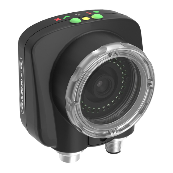
Plus BCR Gen2 Series Sensor 1 Product Description The iVu Plus Barcode Reader (BCR) Gen2 Series Sensor reads a wide variety of barcodes. The package consists of device, lighting, lens, and display. Cables and mounting brackets can be ordered for each application. Additionally, other lenses, filters, and external lights are available. - Page 7 Plus BCR Gen2 Series Sensor Table 2: iVu BCR Models with a Remote Display Ring Light Micro Video Lens Options (Focal Length) C-Mount Options Lens Options 4.3 mm 6 mm 8 mm 12 mm 16 mm 25 mm None...
-
Page 8: Overview
Remote display models: The remote touchscreen display is not required for normal device operation, however, it is needed to configure the device and to monitor inspections. If an integrated ring light is not used, another light source is needed. Various lights are available from Banner Engineering. Operating in external trigger mode requires a triggering source. -
Page 9: Read/No Read, Pass/Fail, Match/No Match
Plus BCR Gen2 Series Sensor 2.3.1 Read/No Read, Pass/Fail, Match/No Match • A Read condition occurs when the configured number of barcodes are found in a scan. These barcodes must be error-free. • A No Read condition occurs when the configured number of barcodes are not found in a scan. -
Page 10: Serial And Ethernet Output
Plus BCR Gen2 Series Sensor • Import the last read data while viewing the Set Data screen. The new data is effective on the first trigger that occurs after this action. • Use Remote Teach. When a Remote Teach occurs, the data of the first read barcode is saved as Data Compare input. Inspections executed on the next trigger use the new data for comparison with subsequently read barcodes. -
Page 11: Imager Resolution
Plus BCR Gen2 Series Sensor 2.4 Imager Resolution The iVu BCR includes an adjustable resolution up to 752×480 pixels. www.bannerengineering.com - Tel: + 1 888 373 6767... -
Page 12: Specifications And Requirements
Plus BCR Gen2 Series Sensor 3 Specifications and Requirements 3.1 Specifications Power Connection Exposure Time 12-pin M12/Euro-style male connector; accessory cable 0.1 ms to 1.049 s required for operation Imager USB 2.0 Host 1/3 inch CMOS 752 × 480 pixels; adjustable Field of View (FOV) 4-pin M8/Pico female connector;... -
Page 13: Dimensions
Plus BCR Gen2 Series Sensor 3.3 Dimensions Micro Video Lens Dimensions 18,4 [.73] [.59] 81,2 [3.20] 51,5 [2.03] 79,2 95,3 [3.12] [3.75] 33,5 [1.32] 19,5 [.77] [.55] [.26] [1.38] Figure 2. Micro Video Lens, Remote Display Models www.bannerengineering.com - Tel: + 1 888 373 6767... - Page 14 Plus BCR Gen2 Series Sensor 18,4 [.73] [.59] 81,2 57,9 [3.20] 51,5 [2.28] [2.03] 43,7 79,2 95,3 [1.72] [3.12] [3.75] 19,5 [.77] [.55] [.26] [1.38] Figure 3. Micro Video Lens, Integrated Display Models All measurements are listed in millimeters [inches], unless noted otherwise.
- Page 15 Plus BCR Gen2 Series Sensor C-Mount Lens Dimensions C-Mount Lens Covers Figure 4. C-Mount Lens, Remote Display Models www.bannerengineering.com - Tel: + 1 888 373 6767...
-
Page 16: Using Ivu Gen1 And Gen2 Devices In The Same Application
Plus BCR Gen2 Series Sensor C-Mount Lens Covers Figure 5. C-Mount Lens, Integrated Display Models All measurements are listed in millimeters [inches], unless noted otherwise. 3.4 Using iVu Gen1 and Gen2 Devices in the Same Application Generation 1 and Generation 2 iVu devices can be used in the same application, however steps must be taken to ensure compatibility. -
Page 17: Banner Engineering Corp. Software Copyright Notice
Banner and its affiliates and channel partners do not warrant that the services are secure, free from bugs, viruses, interruption, errors, theft or destruction. -
Page 18: Installation Instructions
4 Installation Instructions 4.1 Mount the iVu BCR The iVu BCR requires a bracket for mounting. Brackets are available from Banner Engineering. See www.bannerengineering.com . The brackets allow the iVu BCR to be mounted either perpendicular to the part or at an adjustable angle. -
Page 19: Installing A Filter On An Ivu Bcr
Plus BCR Gen2 Series Sensor Pin # Wire Color Description Direction Gray Remote Teach Input Pink External Trigger Input Blue Common (Signal Ground) Input Ready Output Orange Output 3 Output Light Blue RS-232 TX Output Black RS-232 Signal Ground... -
Page 20: Install The Software
Plus BCR Gen2 Series Sensor Note: The light/lens assembly may include an integrated ring light or a blank disk if an integrated ring light is not used. Be careful that the light/lens assembly does not pull out when removing the focusing window. - Page 21 Plus BCR Gen2 Series Sensor 4. Confirm the software destination and availability for users and click Next. 5. Click Install to install the software. 6. Depending on your system settings, a popup window may appear prompting to allow Vision Manager to make changes to your computer.
-
Page 22: Vision Manager
Plus BCR Gen2 Series Sensor 5 Vision Manager Connect to the iVu BCR using Vision Manager PC Software to control the device remotely. After connecting to the device, the interface displays on the Sensor tab. Use the interface in the same manner as the iVu BCR display. -
Page 23: Home Screen
Plus BCR Gen2 Series Sensor Home Screen Home screen provides access to connect to a sensor or emulator, update firmware, and view sensor and Vision Manager software information. The following are available from the Home screen: • Sensor Neighborhood •... - Page 24 Plus BCR Gen2 Series Sensor Figure 13. Active Sensors Tab To connect to a sensor, click next to the desired sensor. To disconnect from a sensor, click To view or change sensor Status, MAC Address, Sensor Name, IP Address, Subnet Mask, and Gateway, click To add the sensor to a Favorites Group, click .
-
Page 25: Sensor Maintenance
Plus BCR Gen2 Series Sensor To remove a group and all the sensors within the group, click the across from the group name. Network Adapters Tab Use the Network Adapters tab on Sensor Neighborhood to view the network adapters that the system searches to find sensors. -
Page 26: Emulators
1. Copy the .bmp files into the InspLog folder in the corresponding iVu BCR emulator folder. For example, copy .bmp files to C:\Users\Public\Documents\Banner Vision Manager\iVu Series\ [iVu model]\InspLog. Note: Remove any existing .bmp or Log files in that folder to avoid confusion. The iVu BCR Emulator automatically runs all .bmp/.log files sequentially according to filename. -
Page 27: About
Plus BCR Gen2 Series Sensor Note: Banner does not recommend setting up inspections using these 8-bit grayscale images because you will need to modify the configuration after loading it on the iVu BCR on the line. A better choice is to set up the inspection on the iVu BCR Emulator using the Inspection Logs from the iVu BCR. -
Page 28: Getting Started
• Capture the barcode with lighting that optimizes its contrast and separates it from the background. Depending on the target, this may mean the integral ring light is not the best choice and other Banner lights should be considered. •... - Page 29 Plus BCR Gen2 Series Sensor Adjust the Focus on a Micro Video Lens Model 1. Use the supplied 1/16 inch hex key to loosen the focusing window locking screw (D), then adjust focus on the iVu BCR using the clear focusing window (B).
-
Page 30: Setting Up A Barcode Application
Plus BCR Gen2 Series Sensor C-Mount Lens Lens Enclosure Retainer Ring Filter Filter Retainer Ring Tool Figure 21. C-Mount Lens Model Components Note: The retainer ring (C) and filter (D) are optional. Filter kits are available separately. 6.2 Setting Up a Barcode Application This section describes how to set up the iVu BCR sensor. -
Page 31: Setting Up For Data Compare
Plus BCR Gen2 Series Sensor • Any case where data does not compare is marked with a solid red bounding box. If the barcode is marked with a dotted red bounding box, this indicates a checksum error or quiet zone violation. -
Page 32: Remote Teach
Plus BCR Gen2 Series Sensor For all subsequent triggers, when the sensor reads the barcode data, it compares it against this reference data. 6.3.1 Remote Teach The Remote Teach function is a method of remotely updating inspection parameters while the iVu BCR is running. The... -
Page 33: Device Home Screen
Plus BCR Gen2 Series Sensor 7 Device Home Screen Use the Home screen on theiVu BCR display to monitor inspections and to configure the iVu BCR. Typically, the part being inspected is centered on the screen. Display Help Button... - Page 34 Plus BCR Gen2 Series Sensor • Execution time of entire inspection Figure 22. Inspection Result Barcode Viewer To view detailed information about a particular barcode, click the arrow next to the Barcode # to access the Barcode Viewer screen.
- Page 35 Plus BCR Gen2 Series Sensor • Total Frames—Total number of images captured for this inspection • Missed triggers—Running total of missed triggers for this inspection • Time Range (ms)—Minimum and maximum inspection times observed for this inspection Click Reset to reset the statistics.
-
Page 36: Device Main Menu
Plus BCR Gen2 Series Sensor 8 Device Main Menu The Main Menu has four sections: • Inspection—Modify inspection settings • Imager—Run the Auto Exposure routine and make adjustments to functions like exposure, gain, and strobe • Logs—Configure and view System and Inspection Logs •... -
Page 37: Icon Reference
Plus BCR Gen2 Series Sensor 8.1 Icon Reference 8.1.1 Action Icons Icon Description The Main Menu icon is on the bottom-left corner of the display on the Home screen. Click this icon to access to sub-menus that are used to set up the iVu BCR. -
Page 38: Display Icons
Plus BCR Gen2 Series Sensor 8.1.2 Display Icons Icon Description The Inspection Passed icon is located in the upper-left of the display. This icon indicates that the last inspection passed the test conditions. One of the possible Inspection Failed icons located in the upper-left of the display. This icon indicates that the last inspection failed. -
Page 39: Device Inspection Menu
Plus BCR Gen2 Series Sensor 9 Device Inspection Menu Main Menu > Inspection The Inspection menu icon is located on the Main Menu. Use the Inspection Menu to set inspection parameters for the currently running inspection and to manage stored inspections. - Page 40 Plus BCR Gen2 Series Sensor DataMatrix Settings Decoder Mode The Decoder Mode determines which decode algorithm to use and how imperfections in barcode images are handled. Fast The sensor uses an algorithm that is tailored for speed. The algorithm does NOT correct for barcode image imperfections.
- Page 41 Plus BCR Gen2 Series Sensor Relaxed Quitezone The Quietzone is a blank margin on either side of a barcode that indicates where the barcode begins and ends. If this Quietzone isn't big enough, the sensor can have trouble decoding the barcode. By enabling Relaxed Quietzone there is a greater tolerance with respect to the quiet zone required before and after the barcode.
- Page 42 Plus BCR Gen2 Series Sensor All Linear Settings The All Linear settings described below apply to the following barcode types: • Code 128 • Code 39 • Code 93 • CODABAR • Interleaved 2 of 5 • EAN13 •...
-
Page 43: Barcode Count
Plus BCR Gen2 Series Sensor Relaxed Quietzone The Quietzone is a blank margin on either side of a barcode that indicates where the barcode begins and ends. If this Quietzone isn't big enough, the sensor can have trouble decoding the barcode. By enabling Relaxed Quietzone there is a greater tolerance with respect to the quiet zone required before and after the barcode. -
Page 44: Data Compare
Plus BCR Gen2 Series Sensor 9.1.3 Data Compare Main Menu > Inspection > Barcode > Data Compare Use the Data Compare menu options to set up the sensor for Data Compare. Note that if the Barcode Count is greater than 1, only the first barcode data can be compared or used in a remote teach operation. -
Page 45: Scan Time Limit
Plus BCR Gen2 Series Sensor • Show last read data—Use the last read barcode data for the data compare • Edit—Enter data using a software keyboard on the display • Mask—Select characters in the data to mask from the data compare Edit Compare Data Click Edit to access the Edit screen. -
Page 46: Properties Menu
Plus BCR Gen2 Series Sensor 9.2 Properties Menu Main Menu > Inspection > Properties Use the Properties menu to specify an Inspection Name and Inspection ID. 9.2.1 Inspection Name Main Menu > Inspection > Properties > Inspection Name The Inspection Name screen displays the name of the current inspection. Edit the name of the inspection on this screen. -
Page 47: Add New
Plus BCR Gen2 Series Sensor 9.3.2 Add New Main Menu > Inspection > Stored Inspections > Add New Use Add New to add a new inspection. The iVu BCR can store up to 30 inspections. When you add a new inspection, it begins running. -
Page 48: Device Imager Menu
Plus BCR Gen2 Series Sensor 10 Device Imager Menu Main Menu > Imager The Imager menu icon is on the Main Menu, and lists parameters that affect the characteristics of the captured image. Use Imager menu to access the auto exposure routine, manually adjust exposure and gain, set trigger and strobe options, as well as set the size of the Field of View (FOV). -
Page 49: Trigger
Plus BCR Gen2 Series Sensor Figure 29. Gain Screen Note: This feature is not effective on the emulator. 10.4 Trigger Main Menu > Imager > Trigger A trigger is a signal that tells the iVu BCR to capture a barcode image and decode it. Five trigger options are available: Continuous Scan, External - Single, External - Gated, Industrial Ethernet Only, or Command. -
Page 50: External-Gated Mode
Plus BCR Gen2 Series Sensor 10.4.3 External-Gated Mode External - Gated mode is similar to Continuous mode. While an external trigger input signal is active, the sensor continues to capture images and run barcode scans until a successful Read occurs or until the External Trigger input signal becomes inactive. -
Page 51: External
Plus BCR Gen2 Series Sensor Figure 31. Strobe Menu 10.6.1 External Main Menu > Imager > Strobe > External The External Strobe is a 5 V dc output used for an external light. Setting options are Always ON, Always OFF, or Exposure Based. -
Page 52: Resolution
Plus BCR Gen2 Series Sensor Figure 32. Imager Menu The maximum FOV is 752×480 for Fine resolution and 376×240 for Coarse resolution. To set the FOV to the maximum, click Set Max. The green box representing the FOV expands to fill the screen. -
Page 53: Device System Menu
Plus BCR Gen2 Series Sensor 11 Device System Menu Main Menu > System The System menu icon is on the Main Menu, and is used to manage the iVu BCR device. From the System menu, select Mode, update the device firmware, back up or restore the device configuration, and perform other general system level operations. -
Page 54: System Configuration Menu
Plus BCR Gen2 Series Sensor Note: Switch between Live Mode and Demo Mode any time by going to Main Menu > System > Mode. 11.2 System Configuration Menu Main Menu > System > Configuration The Configuration screen allows users to save configurations, load new configurations, or reset the device to default values. -
Page 55: System Information
The device can be locked with or without a password. If a password is not used, click Unlock device to unlock the device. When a password is used, it must be 4 digits entered using the keypad. If the password is lost, contact Banner Engineering to obtain a Reset Key. -
Page 56: Ethernet I/O
Plus BCR Gen2 Series Sensor Figure 38. Communications Menu 11.5.1 Ethernet I/O Main Menu > System > Communications > Ethernet I/O Use Ethernet communications to send data out the Ethernet port as part of an inspection, and so that remote devices can communicate with the iVu BCR. -
Page 57: Industrial Ethernet
Plus BCR Gen2 Series Sensor Figure 41. Serial I/O Screen Port Status Main Menu > System > Communications > Serial I/O > Status Use the Port Status screen to make sure that data is entering and exiting the device. This can be useful for debugging issues such as improper wiring, mismatched baud rates, or other serial I/O issues. -
Page 58: Data Export
Plus BCR Gen2 Series Sensor The iVu BCR command channel is a bi-directional communication protocol that currently supports ASCII via the RS-232 serial interface or Ethernet interface, and enables other devices to remotely control the iVu BCR and to access device information and inspection results. - Page 59 Plus BCR Gen2 Series Sensor When Data Export is enabled, the iVu BCR transmits selected inspection data when triggered. Connection Main Menu > System > Communications > Data Export > Connection Use the Connection screen to enable or disable the Data Export.
-
Page 60: Image Export
Plus BCR Gen2 Series Sensor Data Export Advanced Main Menu > System > Communications > Data Export > Advanced During the Data and Image export operation, the iVu BCR output channels might become full. This can occur if the iVu BCR is producing export data (frames) faster than the data can be exported from the device or faster than the client is reading the channel export data (due to bandwidth limitations). -
Page 61: Input Polarity
Plus BCR Gen2 Series Sensor Figure 49. Discrete I/O Menu 11.6.1 Input Polarity Main Menu > System > Discrete I/O > Input Polarity The iVu BCR has two input signals—Trigger and Remote Teach. Both of these signals are edge sensitive. The operation of these signals is dependent on the Input Polarity setting. -
Page 62: Output Type
Plus BCR Gen2 Series Sensor 11.6.3 Output Type Main Menu > System > Discrete I/O > Output Type Select NPN to configure the device's outputs to sink current. Select PNP to configure the device's output for source current. 11.6.4 Output 1 Main Menu >... -
Page 63: Fail Hold Time
Plus BCR Gen2 Series Sensor Use the Display Settings menu to set the Fail Hold Time, LCD Timeout, and to perform a Touch Calibration for the touchscreen display. Enable display optimization from the Advanced menu. Figure 51. Display Settings Menu 11.7.1 Fail Hold Time... -
Page 64: Firmware Update
Use the Firmware Update screen to load the latest device firmware. The Firmware Update screen lists the firmware versions it finds in the BANNER\FIRMWARE folder on the USB flash drive. When you receive a firmware update from Banner Engineering, be sure to put it in the BANNER\FIRMWARE folder on the USB flash drive. -
Page 65: Ivu Output Waveforms
Plus BCR Gen2 Series Sensor Note: Table 5: Required iVu Input Signal Voltage < 2 V dc +10 V dc to 30 V dc Note: If the device used to trigger or remote teach the iVu BCR is a sinking device, these are the options regarding the use of a pull-up resistor: Option 1: Put a pull-up resistor, rated approximately 1 kΩ, between the device's positive (+) voltage and... - Page 66 Plus BCR Gen2 Series Sensor Function Ready Outputs 1, 2, and 3 (Pass) (Fail) (Pass) (Set as Active Pass) Outputs 1, 2, and 3 (Pass) (Pass) (Fail) (Set as Active Fail) Strobe Out (Configure as External & Expose Based) Figure 53.
-
Page 67: Device Logs Menu
Plus BCR Gen2 Series Sensor 12 Device Logs Menu Main Menu > Logs The Logs menu icon is on the Main Menu, and is used to set up, view, and save Inspection Logs, Communication Logs, and System Logs. Figure 54. Logs Menu 12.1 Inspection Logs Menu... -
Page 68: Setup
Plus BCR Gen2 Series Sensor Use the Frame screen to debug an inspection. The screen shows one inspection in read-only mode. Click the upper-left icon to cycle through views: image with annotations, image without annotations, and inspection statistics. When in the Statistics view, the table title has arrows to switch between the Inputs and the Results of the inspection. - Page 69 Plus BCR Gen2 Series Sensor The Communication Log contains logs for the four communications channels: Industrial Ethernet, Command Channel, Data Export, and Image Export. The following features are available for each of the logs: • Click the icon in the upper left corner of the screen to show/hide the time column •...
-
Page 70: Communications Guide
Plus BCR Gen2 Series Sensor 13 Communications Guide 13.1 iVu Plus Communication Summary of Ethernet and Serial The iVu BCR communicates with other devices via Ethernet or a UART serial communications port (RS-232). To establish an Ethernet connection to the iVu BCR, configure the external device with the correct IP address and TCP port. To use the serial communications connection, configure the port settings for baud rate, data bits, parity, and stop bits on the iVu BCR to match the settings of the external device. -
Page 71: Data Export
Plus BCR Gen2 Series Sensor do trigger\x0D\x0A OK\x0D\x0A Control Device, such as a PLC, PC program, or a terminal Response Frame Request Frame iVu BCR Device The following are some of the functionality available via the command channel: •... -
Page 72: Image Export
Plus BCR Gen2 Series Sensor • Pass/Fail Output • Inspection Name • Sensor Result ◦ Pass/Fail Table 7 Sensor Result (see (p. 72) for additional information) ◦ • Frame # • Inspection Time (ms) Table 7: Sensor Results Sensor Type... -
Page 73: Enabling Communications
Plus BCR Gen2 Series Sensor Byte Offset Field ID Size in Bytes Data Type Description 34-63 Reserved byte Reserved for future use Note: If FOV's are adjusted so that they are smaller, the bitmaps will also be smaller. Image Export Sample Application The iVu BCR installation package has an Image Export sample application that provides a way to save exported images. - Page 74 Plus BCR Gen2 Series Sensor Figure 63. Local Area Connection Properties Screen 4. In the Internet Protocol (TCP/IP) Properties dialog, select Use the following IP address and make sure that the IP address is 192.168.0.2, and the subnet mask is 255.255.255.0.
- Page 75 Plus BCR Gen2 Series Sensor Figure 65. Local Area Connection Properties Screen 5. In Internet Protocol (TCP/IPv4) Properties, select Use the following IP address. 6. Make sure that the IP address is 192.168.0.2, and the subnet mask is 255.255.255.0.
- Page 76 Plus BCR Gen2 Series Sensor Figure 68. Connection Screen b. Configure the field and end-of-frame delimiters. Go to Main Menu > System > Communications > Command Channel > Delimiters. Figure 69. Delimiters Screen Valid end-of-frame delimiters are: <comma>, <colon>, <semicolon>, <CR>, <CR><LF>, <LF><CR>, or <ETX>.
- Page 77 Plus BCR Gen2 Series Sensor c. Go to Main Menu > System > Communications > Data Export > Output Format and select the Start String, Delimiter, and End String. Figure 72. Output Format Screen d. Go to Main Menu > System > Communications > Data Export > Advanced.
-
Page 78: Setting Up Serial Communications
Plus BCR Gen2 Series Sensor 13.2.2 Setting Up Serial Communications 1. Electrically connect the control device and the iVu BCR device. On the iVu BCR, the pins/wire colors used for serial communications via RS-232 are shown in the following table. - Page 79 Plus BCR Gen2 Series Sensor d. Verify that the iVu BCR receives and transmits data correctly. 4. Enable Data Export over the serial connection. a. Go to Main Menu > System > Communications > Data Export > Connection and select Serial I/O from the drop-down.
-
Page 80: Testing And Troubleshooting Ivu Bcr Communications
Plus BCR Gen2 Series Sensor During the Data and Image export operation the sensor's output channels might become full. This can occur if the sensor is producing export data (frames) faster than the data can be exported from the device (due to bandwidth limitations) or faster than the client is reading the channel export data. -
Page 81: Ethernet I/O
Plus BCR Gen2 Series Sensor • When a client closes the connection, a log entry indicates that the channel is no longer being listened to 13.3.2 Ethernet I/O Ethernet I/O Status Use the Ethernet I/O Status screen to verify that the Ethernet wiring was correctly set up. In addition to determining if the link has been established, incoming and outgoing traffic can be monitored. - Page 82 Plus BCR Gen2 Series Sensor • Set the Serial port so that the PC port number's baud rate, data, parity, and stop bits match those set up on the iVu Verifying Basic Receive Functionality Use the following instructions to verify that the iVu BCR can receive request frames from the requesting device: 1.
-
Page 83: Command Channel Primer
Plus BCR Gen2 Series Sensor 13.4 Command Channel Primer 13.4.1 Command Channel Commands All iVu BCR command channel request command frames use the following syntax: >> command group item value<EOF> Notes <EOF> is the end-of-frame delimiter. See below for a description. -
Page 84: Conventions Used For Examples
Plus BCR Gen2 Series Sensor Set the String Delimiter parameters to 'None' if strings should not be enclosed in quotation marks. Command Channel Command Synopsis There are a number of general types of commands to do, set, and get sensor data. - Page 85 Plus BCR Gen2 Series Sensor 4. Set Trigger to Command. Go to Main Menu > Imager > Trigger , and from the drop-down list select Command. 5. Issue a trigger command as follows: >> do trigger\x0D\x0A << OK\x0D\x0A 6. Check that the inspection passed.
-
Page 86: Command Channel Reference
Plus BCR Gen2 Series Sensor 8. Get the barcode data read by the iVu sensor. >> get bcr_result data\x0D\x0A << OK\x0D\x0A << "0043000011201"\x0D\x0A 13.4.4 Command Channel Reference Info Command Group Command Group Item Description Info CompanyName The company name as a string. - Page 87 Plus BCR Gen2 Series Sensor Command Group Item Description Ethernet SubnetMask Set a new subnet mask. A Reboot command is required to be sent from the command channel to make the new mask effective. Ethernet Gateway Set a new Gateway IP address. A Reboot command is required to be sent from the command channel to make the new address effective.
- Page 88 Plus BCR Gen2 Series Sensor Command Group Item Description Trigger AbortGated Aborts the gated triggering mode. The device does not transmit a response until the gated triggering option has been aborted and the device has returned to the READY state. This command requires the Command trigger mode.
- Page 89 Plus BCR Gen2 Series Sensor ProductChange Command Group Command Group Item Description Name ] ProductChange Forces the device to switch to the specified inspection. The device does not transmit a response until it has completed the action. Inspections results will be invalid until the next trigger.
- Page 90 Plus BCR Gen2 Series Sensor Examples >> get history passed\x0D\x0A << OK\x0D\x0A << 13\x0D\x0A >> get history startframenumber\x0D\x0A << OK\x0D\x0A << 3\x0D\x0A >> do history clear\x0D\x0A << OK\x0D\x0A Inspection Command Group Command Group Item Description Inspection Status The status of the most recent inspection either Pass, Fail, or Idle (no triggers).
-
Page 91: Command Channel Command Status Register
Plus BCR Gen2 Series Sensor BCR_RESULT Command Group Command Group Item Description BCR_RESULT Count The total number of barcodes found. The most recent inspection value is used. Access to this value requires a valid trigger. BCR_RESULT Data The decoded barcode data strings. Each string starts and ends with the double quote character. -
Page 92: Ivu Bcr Discovery Protocol
13.5 iVu BCR Discovery Protocol The iVu BCR Discovery Protocol is a method to dynamically discover Banner iVu BCR devices on an Ethernet network. The goal is to both be able to find a device and, if necessary, change the IP address of that device so that it is on the same subnet as the controlling PC. -
Page 93: Udp Usage
PC are configured for different subnets and on the same bridged Ethernet network. The contents of the packets used for Banner’s iVu BCR devices are proprietary. The iVu BCR Discovery Protocol is supported by iVu devices from the 2012R1 or later releases. - Page 94 This and the following packet capture examples were created using a free network tracing and troubleshooting software called Wireshark. Banner Engineering Corporation does not provide support for this product nor endorses it. Figure 86. Wireshark DISCOVER Packet Note: In some situations, it is possible for a PC to receive a copy of the packet it sent.
- Page 95 Plus BCR Gen2 Series Sensor Figure 87. Wireshark DISOVER_REPLY Packet Note: In some situations, a network switch/router receives a broadcast packet and duplicates it. This results in the controlling PC receiving multiple responses that are completely identical. Discard multiple replies that have the same correlation tag.
-
Page 96: Message Flow
Plus BCR Gen2 Series Sensor 3. If the above field(s) match the device's equivalent: a. The device compares the new values with the current values. b. If the new values are the same as the current values, the device discards the packet and no further reply is generated. - Page 97 Plus BCR Gen2 Series Sensor Name (“Name=Sensor1”) ▪ MAC (“MAC=00:11:22:33:44:55”) ▪ IP (“IP=192.168.0.1”) ▪ ▪ NetMask (“NetMask=255.255.255.0”) Gateway (“Gateway=0.0.0.0”) ▪ The body of the message looks like the following: SerialNumber=P01238710163241048,Version=TB_v1.1.4,Name=Sensor1,MAC=00:11:22 :33:44:55,IP=192.168.0.1,NetMask=255.255.255.0,Gateway=0.0.0.0 • The packet is broadcast on the network to port 19995. The device uses a pseudo-random back-off time to minimize collisions with other devices.
- Page 98 Plus BCR Gen2 Series Sensor • SerialNumber (“SerialNumber=P01238710163241048”) • IP (“IP=192.168.0.1”) • NetMask (“NetMask=255.255.255.0”) • Gateway (“Gateway=0.0.0.0”) The body of the message looks like the following: SerialNumber=P01238710163241048,IP=192.168.0.1,NetMask=255.255.255.0,Gateway=0.0.0.0 The packet must be sent using the broadcast address of 255.255.255.255. Note: Not all the switches are configured to pass broadcast packets by default. A switch configuration change may be necessary to enable the passing of broadcast packets.
-
Page 99: Industrial Ethernet Overview
Plus BCR Gen2 Series Sensor 14 Industrial Ethernet Overview 14.1 Device Setup 14.1.1 Set IP Address When shipped, the device is assigned a default IP address of 192.168.0.1, a default Subnet Mask of 255.255.255.0, and a default Gateway of 0.0.0.0. To change these defaults, go to Main Menu > System > Communications > Ethernet I/O. -
Page 100: Ivu Bcr Output Values
Plus BCR Gen2 Series Sensor Input Coil Bit Command Description Command Set this bit to 1 to execute the command entered in the Command ID Register 14.2.2 iVu BCR Output Values Using output values, the following information can be obtained: •... -
Page 101: General Command Execution
Plus BCR Gen2 Series Sensor 14.3.1 General Command Execution Point of View of the PLC The following rules apply for the use of input bit commands: • Only one iVu BCR input bit can be set at a time •... -
Page 102: Inputs To The Ivu Bcr (Outputs From The Plc)
Plus BCR Gen2 Series Sensor Allen-Bradley's CompactLogix and ControlLogix family of PLCs uses this communication protocol. The programming software used by these PLCs is RSLogix5000 or Studio 5000 Logix Designer. The iVu BCR can be controlled via EtherNet/IP using assembly objects. From the point of view of a PLC, there are three input assemblies and two output assemblies. - Page 103 Plus BCR Gen2 Series Sensor Note: Assembly Instance 100 does not provide barcode data. WORD # WORD NAME DATA TYPE Input Bits ACK Register (see Input and Output Flags Bits (p. 106)) 16-bit integer Input and Output Flags Bits Output Bits Register (see (p.
- Page 104 Plus BCR Gen2 Series Sensor WORD # WORD NAME DATA TYPE Command Response Int16 16-bit integer 173-174 Command Response Int32 32-bit integer 175-176 Command Response Float Float 177-178 Command Response Length 32-bit integer 179-228 Command Response Data 100 Byte Array...
- Page 105 Plus BCR Gen2 Series Sensor WORD # WORD NAME DATA TYPE Barcode-6 Length 16-bit integer 133-150 Barcode-6 Data 32-bit length + 32-byte array Barcode-7 Type 16-bit integer Barcode-7 Length 16-bit integer 153-170 Barcode-7 Data 32-bit length + 32-byte array...
-
Page 106: Input And Output Flags Bits
Plus BCR Gen2 Series Sensor 14.4.3 Input and Output Flags Bits The Input Bits are used to command execution of basic functions. The Output Bits are used to push single bit outputs from the iVu BCR device to the PLC. The 32 bits of iVu BCR output can also be accessed using the bits of the first two Output Registers (Input Bits ACK Register(word 0) and Output Bits Register (word1)). -
Page 107: Ivu Plus Barcode Reader (Bcr) Gen2 Series Sensor Eds File Installation In Controllogix Software
Plus BCR Gen2 Series Sensor 14.4.7 iVu Plus Barcode Reader (BCR) Gen2 Series Sensor EDS File Installation in ControlLogix Software Use the EDS Hardware Installation Tool to register the Electronic Data Sheet (EDS) file. 1. On the Tools menu, click EDS Hardware Installation Tool. - Page 108 Plus BCR Gen2 Series Sensor Figure 92. Select File to Register 5. Click Next to register the tested file. Figure 93. Register the Tested File 6. Click Next when you see the icon associated with the EDS file. www.bannerengineering.com - Tel: + 1 888 373 6767...
- Page 109 Plus BCR Gen2 Series Sensor Figure 94. Rockwell Automation's EDS Wizard 7. Click Next to register the EDS file. Figure 95. Register the EDS File 8. Click Finish to close the EDS Wizard . 9. Right-click on the PLC's Ethernet adapter and select New Module...
- Page 110 Plus BCR Gen2 Series Sensor Figure 97. Select Module Type 11. Enter a name, description (optional), and IP address for the iVu BCR. Figure 98. New Module 12. Click Change in the Module Definition field. www.bannerengineering.com - Tel: + 1 888 373 6767...
- Page 111 Plus BCR Gen2 Series Sensor Figure 99. Module Definition 13. Select the desired connection in the Module Definition window. Each of the items in the Name list represents a fixed grouping of input and output assembly instances: Small Assemblies •...
-
Page 112: Rslogix5000 Configuration
Plus BCR Gen2 Series Sensor Figure 101. Download to the PLC Figure 101 The connection looks like the one in (p. 112). 14.4.8 RSLogix5000 Configuration To create an implicit Class 1 configuration to the iVu BCR using EtherNet/IP when using a ControlLogix family PLC, configure the iVu BCR as a “Generic Ethernet Module”... - Page 113 Plus BCR Gen2 Series Sensor Figure 103. Select Module 2. Configure the Module Properties. Note: The data type in the Comm Format must be changed to an INT. Inputs to the iVu BCR (Outputs from the PLC) Outputs from the iVu BCR (Inputs to the PLC) (p.
- Page 114 Plus BCR Gen2 Series Sensor Figure 104. Example: PLC Input Assembly Instance 0×64 (100), PLC Output Assembly Instance 0×70 (112) Figure 105. Example: PLC Input Assembly Instance 0×65 (101), PLC Output Assembly Instance 0×71 (113) www.bannerengineering.com - Tel: + 1 888 373 6767...
- Page 115 Plus BCR Gen2 Series Sensor Figure 106. iVu Plus BCR—PLC Input Assembly (102), PLC Output Assembly (113) Figure 107. Select or clear the Unicast Connection checkbox as desired Note: The minimum allowed RPI is 50 ms. 3. If the module configuration was successful, the following information displays: Figure 108.
- Page 116 Figure 109. ERROR: Assembly Instance Number and/or Size Incorrect Figure 110. ERROR: iVu BCR Not Powered Up or Ethernet Cable Not Attached 4. Locate the memory map setup from the Banner module to the PLC memory map. C = Configuration (not used)
- Page 117 Plus BCR Gen2 Series Sensor The iVu BCR memory map expanded. I = Inputs to PLC (outputs from the device). Figure 112. Memory Map Expanded Sample map demonstrating string values: Figure 113. Memory Map: Default Note: ControlLogix string format. "iVu Plus Image Sensor"...
-
Page 118: Modbus/Tcp
Plus BCR Gen2 Series Sensor All data is initially transferred as "INT" data type. An ASCII string looks like gibberish in this format. Changing the "style" to ASCII instead of "Decimal" reveals the correct string data. Figure 114. Memory Map: "Style" changed to ASCII 14.5 Modbus/TCP... - Page 119 Plus BCR Gen2 Series Sensor 05: Force Single Coil Register Bit Position WORD Name reserved 00010 reserved 00011 00012 reserved reserved 00013 reserved 00014 00015 reserved 00016 Command Table 14: Input ACK Bits (Inputs 10001-10016) 02: Read Input Status...
-
Page 120: Ivu Bcr Input Values
Plus BCR Gen2 Series Sensor 02: Read Input Status Register Bit Position WORD Name 10024 Output 3 reserved 10025 10026 reserved reserved 10027 reserved 10028 10029 Missed Trigger 10030 Teach Error 10031 System Error 10032 Execution Error 14.5.1 iVu BCR Input Values Holding Registers (40000) are used by the PLC or HMI to write values to the iVu BCR device. - Page 121 Plus BCR Gen2 Series Sensor Table 17: iVu Plus Output Values (Modbus/TCP Input or Holding Registers) 04: Read Input Registers or 03: Read Holding Registers Input REG # Holding REG # WORD NAME DATA TYPE 1001 Input ACK Bits (see...
-
Page 122: Input And Output Bits
Plus BCR Gen2 Series Sensor 04: Read Input Registers or 03: Read Holding Registers Input REG # Holding REG # WORD NAME DATA TYPE 284-301 1284-301 Barcode-3 Data 32-bit length + 32 Unicode character array 1302 Barcode-4 Type 16-bit integer... -
Page 123: Plc5, Slc500, And Micrologix (Pccc)
Plus BCR Gen2 Series Sensor reserved reserved reserved reserved reserved reserved reserved reserved reserved Command Set BCR Set BCR Gated Trigger Teach Product Mask String Trigger Latch Change Read-only Status Bits are outputs from the iVu BCR (inputs to the PLC or HMI). They are used to report the basic status of the iVu BCR and the last inspection run. - Page 124 Plus BCR Gen2 Series Sensor PLC Read Message Command This Controller Communications Command = PLC5 Read Data Table Address = Integer table "Nx" Target Device Data Table Address = N7:x Figure 115. General tab: Example message command reading from N7 table on the iVu BCR and sending the data to the N7 table on the PLC...
- Page 125 Plus BCR Gen2 Series Sensor To Address = IP address of the iVu BCR Figure 116. MultiHop tab: IP Address of the iVu BCR is entered here www.bannerengineering.com - Tel: + 1 888 373 6767...
- Page 126 Plus BCR Gen2 Series Sensor PLC Write Message Command This Controller Communications Command = PLC5 Write Data Table Address = Integer table "Nx" Target Device Data Table Address = N14:x Figure 117. General tab: Example message command writing to N14 table on the iVu BCR from the N14 table of the PLC...
-
Page 127: Inputs To Ivu Bcr (Outputs From Plc)
Plus BCR Gen2 Series Sensor To Address = IP address of the iVu BCR Figure 118. MultiHop tab: IP address of the iVu BCR is entered here 14.6.2 Inputs to iVu BCR (Outputs from PLC) The registers below are used by the PLC to push values to the iVu BCR device. MSG (message) commands are used to write (N14) to the iVu BCR. - Page 128 Plus BCR Gen2 Series Sensor Table 22: PCCC PLC Input Registers (iVu BCR Outputs, N7 Table) WORD # WORD NAME DATA TYPE Input Bits ACK Register (see Input and Output Flags (p. 129)) 16-bit integer Input and Output Flags Output Bits Register (see (p.
-
Page 129: Input And Output Flags
Plus BCR Gen2 Series Sensor WORD # WORD NAME DATA TYPE 303-320 Barcode-4 Data 32-bit length + 32-byte array Barcode-5 Type 16-bit integer Barcode-5 Length 16-bit integer 323-340 Barcode-5 Data 32-bit length + 32-byte array Barcode-6 Type 16-bit integer... -
Page 130: Profinet
Plus BCR Gen2 Series Sensor ® 14.7 PROFINET ® PROFINET is a data communication protocol for industrial automation and processes. PROFINET IO defines how controllers (IO controllers) and peripheral devices (IO devices) exchange data in real time. The image sensor, iVu BCR, supports PROFINET IO. The data communication protocol is TCP/IP; the data transmission medium is copper wire;... - Page 131 Plus BCR Gen2 Series Sensor Figure 120. Connection Screen 3. Click (only one time) on the Arrow button on the bottom left to return to the Industrial Ethernet window. Figure 121. Industrial Ethernet Menu 4. Click Map to configure the PROFINET module map.
- Page 132 Plus BCR Gen2 Series Sensor Adding sensor-specific output information, including data from decoded barcode symbols, requires the use of a BCR sensor output submodule, plugged into Slot 2 Subslot 1. The iiVu BCR provides different options for configuring this submodule, based on the space required by the decoded barcode data. The selection of sensor output submodules is based on size, allowing the user to control network bandwidth use.
- Page 133 Plus BCR Gen2 Series Sensor Table 27: BCR Control and Status Module (Ident 0x00000011) Number of Physical Subslots Subslot Label Subslot Number 1.1 BCR Inspection Result Submodule 1 (0x1) 1.2 BCR Device Control Submodule 2 (0x2) Table 28: BCR Sensor Output Module (Ident 0x00000041)
- Page 134 Plus BCR Gen2 Series Sensor Table 32: BCR Inspection Result Submodule (Ident 0x0102) PLC Input Data Name Input Data Type PLC Output Data Name Output Data Type Inspection Status Word Unsigned16 Not applicable Not applicable Inspection Number Unsigned32 Sensor Pass/Fail Status...
- Page 135 Plus BCR Gen2 Series Sensor Sensor Output Submodules The First Barcode Submodule contains barcode output data. This user-enabled submodule is optional and plugged into Slot 2 Subslot 1. The First Barcode Submodule has six versions with 16, 32, 64, 128, 256, and 512 bytes, depending on the length of the output string.
- Page 136 Plus BCR Gen2 Series Sensor Table 37: 128-Byte First Barcode Submodule (Ident 0x00022) PLC Input Data Name Input Data Type PLC Output Data Name Output Data Type Frame number Unsigned32 Not applicable Not applicable Sensor type Unsigned16 Total number of barcodes found...
- Page 137 Plus BCR Gen2 Series Sensor Table 40: Multiple Barcodes Submodule (Ident 0x00026) PLC Input Data Name Input Data Type PLC Output Data Name Output Data Type Frame number Unsigned32 Not applicable Not applicable Sensor type Unsigned16 Total number of barcodes found...
- Page 138 Plus BCR Gen2 Series Sensor Compare String Submodules The Compare String Submodules contain controller input and controller output data, as well as BCR controls. This user- enabled submodule is optional and plugged into Slot 3 Subslot 1. The Compare String Submodule has six versions, depending on the length of the compare string.
- Page 139 Plus BCR Gen2 Series Sensor Table 43: 64-Byte Compare String Submodule (Ident 0x0006) PLC Input Data Name Input Data Type PLC Output Data Name Output Data Type Return status code of the string or Unsigned16 BCR control word Unsigned16...
- Page 140 Plus BCR Gen2 Series Sensor Table 45: 256-Byte Compare String Submodule (Ident 0x0008) PLC Input Data Name Input Data Type PLC Output Data Name Output Data Type Return status code of the string or Unsigned16 BCR control word Unsigned16...
- Page 141 Plus BCR Gen2 Series Sensor Table 47: Numeric Command Submodule (Ident 0x00012) PLC Output Data Name Output Data Type PLC Input Data Name Input Data Type Flag indicates when to apply the command Unsigned16 Not applicable Not applicable Numeric ID of the command...
- Page 142 Plus BCR Gen2 Series Sensor Table 49: Text Command 64-byte Submodule (Ident 0x00014) PLC Output Data Name Output Data Type PLC Input Data Name Input Data Type Flag indicates when to apply the command Unsigned16 Not applicable Not applicable...
- Page 143 Plus BCR Gen2 Series Sensor Table 51: Numeric Response Submodule (Ident 0x00050) PLC Input Data Name Input Data Type PLC Output Data Name Output Data Type Flag indicating when to Command ACK Unsigned16 Not applicable Not applicable Numeric Command Status...
-
Page 144: Configuration Instructions
Installing the Banner iVu BCR GSD File Use these instructions to install the Banner iVu BCR GSD file in the Siemens TIA Portal (v13) software. Use these instructions as a basis for installing the Banner iVu BCR GSD file in another controller (PLC). - Page 145 Plus BCR Gen2 Series Sensor 2. Start the Siemens TIA Portal (v13) software. 3. Click Open existing project. 4. Select a project and open it. 5. Click Devices & networks after the project has been uploaded. Figure 125. Devices and Networks 6.
- Page 146 Plus BCR Gen2 Series Sensor 7. Click Options and select Install general station description file (GSD). Figure 127. Options—Install the GSD The Install general station description file window opens. 8. Click the browse button (...) to the right of the Source path field.
- Page 147 The system installs the iVu BCR GSD file and places it in the Hardware catalog. In the above example, the iVu BCR GSD file is located under Other field devices > PROFINET IO > Sensors > Banner Engineering Corp. > Banner Vision Sensors >...
- Page 148 Plus BCR Gen2 Series Sensor 4. Click Devices & networks after the project has been uploaded. Figure 130. Devices and Networks 5. Click Configure networks. Figure 131. Configure Networks Network view displays. Note: For Step 6 through Step 10, Network view must be open.
- Page 149 Plus BCR Gen2 Series Sensor Figure 132. Hardware Catalog In the above example, the iVu BCR device is located under Other field devices > PROFINET IO > Sensors > Banner Engineering Corp > Banner Vision Sensors > iVu Series.
- Page 150 Plus BCR Gen2 Series Sensor Figure 133. Drag to Connect The connection is made. 9. Double-click the iVu BCR icon to open the Device window. 10. Select the desired modules or submodules from the Hardware catalog and drag them onto the Device overview tab on the Device view tab.
- Page 151 Plus BCR Gen2 Series Sensor Figure 136. Set IP Address The project sets the IP address of the device. 11. Enter the IP address. 12. Right-click on the device icon and select Online & diagnostics. Figure 137. Select Online & Diagnostics Figure 138.
- Page 152 Plus BCR Gen2 Series Sensor Figure 139. Assign IP Address—Accessible Devices The Select device window searches the network for available devices. 15. Determine the device to be adjusted via the MAC address and select it. Note: Use the display to find the MAC address. Main Menu > System > Communications >...
- Page 153 Plus BCR Gen2 Series Sensor Note: PROFINET devices commonly lack an IP address on startup (IP address = all zeros). However, iVu BCR devices require an IP address to connect to Vision Manager to set the device configuration. By default, each camera shipped from the factory is assigned the IP address 192.168.0.1. The default address can be changed using Vision Manager.
- Page 154 Plus BCR Gen2 Series Sensor Figure 143. Ethernet Addresses 6. Deselect Generate PROFINET device name automatically. Figure 144. PROFINET Device Name 7. Enter a unique name in the PROFINET device name field. 8. Enter a unique device number in the Device number field.
- Page 155 Using Siemens SIMATIC STEP 7 (v5.5) Software Installing the Banner iVu BCR GSD File Use these instructions to install the Banner iVu BCR GSD file in the Siemens SIMATIC STEP 7 (v5.5) software. 1. Start Siemens SIMATIC Manager. 2. Select an existing project and open it.
- Page 156 Plus BCR Gen2 Series Sensor Figure 149. Object Hierarchy List 4. Double-click the Hardware icon in the Station level window. Figure 150. Double-Click the Hardware Icon The Hardware configuration window opens. 5. In the Hardware configuration window, click Options > Install GSD File..
- Page 157 The Hardware catalog appears on the right side of the Hardware configuration window. Figure 153. Hardware Catalog The location in the Hardware catalog is PROFINET IO > Additional Field Devices > Sensors > Banner Vision Sensors > iVu Series ®...
- Page 158 Plus BCR Gen2 Series Sensor 1. Start Siemens SIMATIC Manager. 2. Select an existing project and open it. 3. Select the Station (PLC) from the Object Hierarchy list. Figure 154. Object Hierarchy List 4. Double-click the Hardware icon in the Station level window to open the Hardware configuration window.
- Page 159 Plus BCR Gen2 Series Sensor 9. Add modules and submodules. Changing the Device IP Address Use these instructions for the Siemens SIMATIC STEP 7 (v5.5) software. 1. Start Siemens SIMATIC Manager. 2. Select an existing project and open it.
- Page 160 Plus BCR Gen2 Series Sensor Figure 161. Edit Ethernet Node Screen This starts a search for all PROFINET devices on the network and shows the found devices. 7. Select the device to be modified. Figure 162. Browse Network Screen 8.
- Page 161 Plus BCR Gen2 Series Sensor Figure 163. Edit Ethernet Note Screen The Edit Ethernet Node window is updated. 9. Set the IP address to the desired value. 10. Click Assign IP Configuration at the bottom left of the Set IP configuration section.
- Page 162 Plus BCR Gen2 Series Sensor Figure 165. Object Hierarchy List 4. Double-click the Hardware icon in the Station level window to open the Hardware configuration window. Figure 166. Double-click the Hardware Icon 5. Select PLC > Ethernet > Edit Ethernet Node.
- Page 163 Plus BCR Gen2 Series Sensor Figure 168. Edit Ethernet Node Screen ® This starts a search for all PROFINET devices on the network and shows the found devices. 7. Select the device to be modified. Figure 169. Browse Network Screen 8.
- Page 164 Plus BCR Gen2 Series Sensor Figure 170. Edit Ethernet Node Screen The Edit Ethernet Node window is updated. 9. Enter a name with lower case letters in the Device name field. 10. Click Assign Name. Figure 171. Edit Ethernet Node Message The Device name is updated.
-
Page 165: Sample Timing Diagrams
Plus BCR Gen2 Series Sensor 14.8 Sample Timing Diagrams X, Y, Z: Represent snapshot in time Product Change X+Y+Z Product Change Ready Product Change ProductChange ProductChange ProductChange Verify : Verify : ACK = ‘1 ’ Ready = 1 Ready = 1... - Page 166 Plus BCR Gen2 Series Sensor Teach Latch X + Y X + Y + Z Teach Latch Ready Teach Latch ACK TeachLatch TeachLatch TeachLatch ACK Verify : Verify : = ‘1 ’ Ready = 1 Ready = 1 Teach will...
- Page 167 Plus BCR Gen2 Series Sensor Trigger X + Y X + Y + Z Trigger Ready TriggerACK Trigger = 1 Trigger = 0 Verify : Verify : TriggerACK = ‘1 ’ Ready = 1 Ready = 1 Read Results...
-
Page 168: Command Channel Command Status Register
Plus BCR Gen2 Series Sensor Gated Trigger X + Y X + Y + Z M Gated Trigger Ready Gated Trigger ACK GatedTrigger GatedTrigger GatedTrigger GatedTrigger = 0 (Abort ) Inspection could not be completed GatedTriggerACK Verify : Verify : = ‘1 ’... -
Page 169: Networking And Tcp/Ip Diagnostics
Plus BCR Gen2 Series Sensor Figure 176. System Log Screen—Ethernet Link 5. Go to System > Communications > Ethernet I/O, and click Status. 6. Verify that the Link Status is Connected, and that the link parameters, such as speed and duplex settings are as expected. - Page 170 Plus BCR Gen2 Series Sensor Figure 179. Ethernet I/O Status Screen 5. On the PC attached to your LAN, open the Command window. To do this, click Start > Run, enter cmd, and click OK. A command window displays.
-
Page 171: Industrial Protocols Troubleshooting
Plus BCR Gen2 Series Sensor • If you are running several overlapping subnets, you may want to consult your IT department to ensure that the routing for the network is configured correctly • If you are trying to access the camera through a gateway or a VPN router, verify that these devices are configured such that they allow traffic from the iVu BCR device to reach the destination device 14.10.3 Industrial Protocols Troubleshooting... - Page 172 Plus BCR Gen2 Series Sensor I/O messaging is based on UDP/IP, and utilizes Multicast addressing when sending PLC input assemblies. It is the default mode of operation for I/O messages in PLCs. Many PLCs also support Unicast (direct) addressing for PLC input assemblies, but need to be specially configured.
- Page 173 Plus BCR Gen2 Series Sensor PROFINET Discovering iVu BCR Devices The Siemens TIA Portal (v13) software discovery and configuration protocols are used to discover iVu BCR devices on a network. 1. Start the Siemens TIA Portal (v13) software. 2. Click Open an existing project.
- Page 174 Plus BCR Gen2 Series Sensor Figure 190. Industrial Ethernet Screen Note: Green communication log icons mean flawless communication. Red communication icons mean communication errors. 2. Click the Arrow button on any log entry in the communication log to access the Communication Log Detail window.
- Page 175 Plus BCR Gen2 Series Sensor Note: An expanded description of the communication supports better diagnostics. www.bannerengineering.com - Tel: + 1 888 373 6767...
-
Page 176: Additional Information
Plus BCR Gen2 Series Sensor Diagnosing Errors The Siemens TIA Portal (v13) software includes numerous diagnostic tools. When a computer is connected to the controller (PLC), diagnostic information is available. The controller (PLC) generates a message that displays in the Diagnostics window. - Page 177 Plus BCR Gen2 Series Sensor Command Command ID Description Data Type Trigger Trigger Mode 10001 The iVu BCR triggering mode. This value must match the Int16 modes supported by the iVu BCR. Product Change Product Change By This command forces the iVu BCR to switch to the...
- Page 178 Plus BCR Gen2 Series Sensor Trigger Mode 1000 Description External Inspections are initiated via the electrical trigger wire. Internal Inspections run continuously at the specified period (electrical trigger inputs are ignored). External Gated Gated barcode inspections are started and/or aborted via the electrical trigger wire.
- Page 179 Plus BCR Gen2 Series Sensor Numeric ID Text ID Description 10350 ARGUMENTS_DETECTED Get command received with unneeded arguments 10351 INVALID_ARGUMENT_TYPE Item ID specified must be an item (not a group or method) 10500 DATA_SET_EMPTY Data export operation returned no results.
- Page 180 Plus BCR Gen2 Series Sensor 1. Write the number 10001 as a 16-bit integer into the Command ID register. 2. Toggle the Command bit from 0 to 1 (bit 15 in the Input Bits/Input Coil Bits register). 3. Wait for the Command ACK flag to go from 0 to 1 (bit 15 in the Input Bits ACK/Input Coil Bits ACK register).
- Page 181 Plus BCR Gen2 Series Sensor 5. Verify that the Execution Error flag is not set (that is, the value should be 0). This is bit 15 in the Output Bits/Status Coil Bits register. If the value is 1, read the Error Code register for more information.
-
Page 182: Troubleshooting
Go to Main Menu > Logs > System Logs . b. Click Clear System Error. A device reboot is not required. 3. If the error occurs again, try rebooting the iVu BCR to see if that fixes the problem. If the problem persists, contact Banner Engineering. 15.1.2 Warnings Warnings are atypical conditions that the iVu BCR detects and fixes. -
Page 183: How To Debug Using Inspection Logs
The device configuration is saved to the USB flash drive. The location of these files on the USB flash drive displays after the operation is completed. The configuration file is saved in the [USB:]\BANNER\[SENSOR_NAME] folder. For example, if the device name is myName, the configuration file (CONFIG.CFG) path is [USB:]\BANNER\myName www.bannerengineering.com - Tel: + 1 888 373 6767... -
Page 184: Vision Manager Error Codes
Emulator. All configuration changes are automatically saved to the CONFIG.CFG file on the PC. 13. Copy the modified device configuration file from the PC to the USB flash drive ([USB:]\BANNER\myName). 14. Disconnect the USB flash drive from the PC. - Page 185 Plus BCR Gen2 Series Sensor Error Code Description Recommended Solution 10010 A connection to the sensor could • Verify the sensor is energized not be established. One or more • Verify the sensor communication cable is connected required channels failed to connect.
- Page 186 Plus BCR Gen2 Series Sensor Error Code Description Recommended Solution 10022 The connection to the sensor was • Verify the sensor is energized lost while sending data. • Verify the sensor communication cable is connected • Verify all inline network equipment is energized, properly configured and connected •...
- Page 187 Verify the sensor's firmware version is compatible with this address rejected the connection application attempt. This can happen when the • Verify the device at the specified IP address is a Banner Vision network device does not support sensor the Vision Manager protocol. 10050 The connection to the sensor was •...
- Page 188 Plus BCR Gen2 Series Sensor Error Code Description Recommended Solution 10054 The Connection to the sensor was • Verify the sensor is energized lost while receiving data. • Verify the sensor communication cable is connected • Verify all inline network equipment is energized, properly configured and connected •...
- Page 189 The connection to the sensor was • Install an newer version of this application lost while sending data. • Verify the device at the specified IP address is a Banner Vision sensor • Verify the sensor's firmware version is compatible with this application •...
- Page 190 • Install an newer version of this application aborted by this application due to • Verify the device at the specified IP address is a Banner Vision an internal processing error. sensor • Verify the sensor's firmware version is compatible with this application •...
- Page 191 Plus BCR Gen2 Series Sensor Error Code Description Recommended Solution 20010 An application error occurred while • Go to Sensor Neighborhood and reconnect to the sensor refreshing the display. There was a problem creating screen elements. 20011 An application error occurred while •...
- Page 192 Plus BCR Gen2 Series Sensor Error Code Description Recommended Solution 20154 There was a problem closing the • Reboot the computer to end any processes which did not shut previous emulator session. down properly 20155 There was a problem closing the •...
-
Page 193: Accessories
Plus BCR Gen2 Series Sensor 16 Accessories 16.1 Power Cable — Required 12-Pin M12/Euro-Style Cordsets with Open Shield Model Length Style Dimensions Pinout (Female) MQDC2S-1206 1.83 m (6 ft) 44 Typ. MQDC2S-1215 4.57 m (15 ft) 1 = White MQDC2S-1230 9.14 m (30 ft) -
Page 194: Ethernet Cable Options
Plus BCR Gen2 Series Sensor 16.3 Ethernet Cable Options RJ45 Ethernet to 4-Pin Threaded M8/Pico-Style Cordsets Model Length Style Dimensions Pinout IVUC-E-406 1.83 m (6 ft) 35.0 IVUC-E-415 4.57 m (15 ft) ø 9.5 IVUC-E-430 9.14 m (30 ft) -
Page 195: Brackets
Plus BCR Gen2 Series Sensor 16.6 Brackets For Use with Integrated Display Models SMBIVUB SMBIVURAL • Bottom mounting bracket • Right-angle bracket for mounting the device from the • Black anodized aluminum Ø4.4 left • Hardware included Ø22.5 •... -
Page 196: Micro Video Lens Accessories
Plus BCR Gen2 Series Sensor 16.7 Micro Video Lens Accessories 16.7.1 Micro Video Lens Models Model Lens Description LMF04 15 4.3 mm lens LMF06 6 mm lens LMF08 8 mm lens LMF12 12 mm lens LMF16 16 mm lens... -
Page 197: C-Mount Lens Enclosure Models
Plus BCR Gen2 Series Sensor 16.8.2 C-Mount Lens Enclosure Models Model Description IVUSLC50-P Sealed C-mount lens enclosure IVUSLC75-P 16.8.3 C-Mount Lens Filters — Optional Model Description FLTR Red filter kit FLTB Blue filter kit FLTG Green filter kit FLTI IR Filter kit www.bannerengineering.com - Tel: + 1 888 373 6767... -
Page 198: Product Support And Maintenance
Warranty Service Contact Banner Engineering for troubleshooting of this device. Do not attempt any repairs to this Banner device; it contains no field-replaceable parts or components. If the device, device part, or device component is determined to be defective by a Banner Applications Engineer, they will advise you of Banner's RMA (Return Merchandise Authorization) procedure. -
Page 199: How To Set Or Modify A Device Name Using The Emulator
The folder C:\Users\Public\Documents\Banner Vision Manager\Firmware\[Vision sensor model] opens. 3. Copy the folder called "BANNER" to the root of the USB flash drive. 4. Disconnect the USB flash drive from the PC. 5. Connect the USB cable to the iVu BCR. -
Page 200: How To Reset The Device Password
Banner Engineering Corp. warrants its products to be free from defects in material and workmanship for one year following the date of shipment. Banner Engineering Corp. will repair or replace, free of charge, any product of its manufacture which, at the time it is returned to the factory, is found to have been defective during the warranty period. This warranty does not cover damage or liability for misuse, abuse, or the improper application or installation of the Banner product. -
Page 201: Fcc Part 15 And Can Ices-3 (A)/Nmb-3(A)
Plus BCR Gen2 Series Sensor 17.5 FCC Part 15 and CAN ICES-3 (A)/NMB-3(A) This device complies with part 15 of the FCC Rules and CAN ICES-3 (A)/NMB-3(A). Operation is subject to the following two conditions: This device may not cause harmful interference, and This device must accept any interference received, including interference that may cause undesired operation. - Page 202 Index data compare 44, 45 image export sample application 73 data export 58–60, 70, 71 imager Active Sensors tab 23 data export log 80 auto exposure 48 Advanced Display screen 63 data export sample application 72 exposure 48 auto exposure 48 data model 130, 132–135, 138, 140, focus 50 FOV 51...
- Page 203 System 53–65 Micro QR Code 6, 39–43 reboot 63 Modbus/TCP 118, 120, 122 resolution 52 Mode menu 53 RS-232 70–72 module 132 About 27 Active Sensors 23 Favorites 24 Network Adapters 25 sample application Network Adapters tab 25 teach command group 88 command channel 71 time limit 45 image export 73...
Need help?
Do you have a question about the iVu Plus BCR Gen2 Series and is the answer not in the manual?
Questions and answers