Sign In
Upload
Download
Table of Contents
Contents
Add to my manuals
Delete from my manuals
Share
URL of this page:
HTML Link:
Bookmark this page
Add
Manual will be automatically added to "My Manuals"
Print this page
×
Bookmark added
×
Added to my manuals
Manuals
Brands
Banner Manuals
Accessories
Q3XTBLD150-Q8
Instruction manual
Banner Q3XTBLD150-Q8 Instruction Manual
Laser contrast sensor
Hide thumbs
1
Table Of Contents
2
3
4
5
6
7
8
9
10
11
12
13
14
15
16
17
18
19
20
21
22
23
24
25
26
27
28
29
30
31
page
of
31
Go
/
31
Contents
Table of Contents
Troubleshooting
Bookmarks
Table of Contents
Table of Contents
Product Description
Models
Overview
Features
Display and Indicators
Buttons
Laser Description and Safety Information
Installation
Install the Safety Label
Sensor Orientation
Sensor-To-Background Position
Sensor Mounting
Wiring Diagram
Cleaning and Maintenance
Sensor Programming
Setup Mode
Output Operation
TEACH Menu
Offset Percentage
Response Speed
Output Timing Delays
Input Wire Function
Sensitivity
Cut-Off Operation
Display View
Exit the Top Menu
Reset to Factory Defaults
Manual Adjustments
Remote Input
Select the TEACH Mode Using the Remote Input
Reset to Factory Defaults Using the Remote Input
Locking and Unlocking the Sensor Buttons
TEACH Procedures
Detection Reliability
Two-Point Static TEACH
Dynamic TEACH
Window Set
Light Set
Dark Set
Sync Master/Slave
Sensor Menu Map
Specifications
Performance Curves
Dimensions
Abbreviations
Troubleshooting
Accessories
Cordsets
Brackets
Contact Us
Banner Engineering Corp Limited Warranty
Advertisement
Quick Links
Download this manual
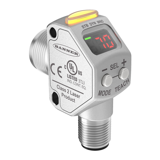
Q3X Laser Contrast Sensor
Instruction Manual
Original Instructions
181485 Rev. E
12 July 2017
©
Banner Engineering Corp. All rights reserved
181485
Table of
Contents
Previous
Page
Next
Page
1
2
3
4
5
Advertisement
Table of Contents
Need help?
Do you have a question about the Q3XTBLD150-Q8 and is the answer not in the manual?
Ask a question
Questions and answers
Related Manuals for Banner Q3XTBLD150-Q8
Accessories Banner Q3X Instruction Manual
Laser contrast sensor (33 pages)
Accessories Banner Q3XTBLD-Q8 Quick Start Manual
Q3x series laser contrast sensor (8 pages)
Accessories Banner Q3X Installation
Laser contrast sensor (2 pages)
Accessories Banner Q3XTBLD200-Q8 Instruction Manual
Laser contrast sensor (31 pages)
Accessories Banner Q4X Instruction Manual
Stainless steel analog laser sensor (37 pages)
Accessories Banner Q4X Quick Start Manual
Stainless steel laser sensor (13 pages)
Accessories Banner Q4X Quick Start Manual
Stainless steel laser sensor with dual discrete outputs and io-link (14 pages)
Accessories Banner Q4X Quick Start Manual
Stainless steel analog laser sensor (11 pages)
Accessories Banner q4x Instruction Manual
Stainless steel laser sensor (29 pages)
Accessories Banner Q4X Quick Start Manual
Stainless steel laser sensor (10 pages)
Accessories Banner Q4X Instruction Manual
Stainless steel laser sensor with dual discrete outputs and io-link (46 pages)
Accessories Banner Q4X Quick Start Manual
Stainless steel laser sensor for clear object detection (9 pages)
Accessories Banner Q4X Quick Start Manual
Stainless steel laser sensor with dual discrete outputs and io-link (13 pages)
Accessories Banner Q5X Quick Start Manual
Laser triangulation sensor with analog outputs (13 pages)
Accessories Banner R-GAGE Q130RA Series Instruction Manual
(26 pages)
Accessories Banner WORLD-BEAM QS18 Expert Series Instruction Manual
With io-link (30 pages)
This manual is also suitable for:
Q3xtbld-q8
Q3xtbld50-q8
Q3xtbld100-q8
Q3x series
Q3xtbld200-q8
Table of Contents
Print
Rename the bookmark
Delete bookmark?
Delete from my manuals?
Login
Sign In
OR
Sign in with Facebook
Sign in with Google
Upload manual
Upload from disk
Upload from URL


Need help?
Do you have a question about the Q3XTBLD150-Q8 and is the answer not in the manual?
Questions and answers