
Related Manuals for Banner R-GAGE Q130RA Series


Summary of Contents for Banner R-GAGE Q130RA Series
- Page 1 ® R-GAGE Q130RA Sensor Instruction Manual Original Instructions 208831 Rev. B 15 May 2019 © Banner Engineering Corp. All rights reserved 208831...
-
Page 2: Table Of Contents
10.2 Quick Disconnect (QD) Cordsets ..............................23 10.3 Brackets and Enclosures ................................23 11 Product Support and Maintenance ..........................25 11.1 Repairs ......................................25 11.2 Contact Us ....................................25 11.3 Banner Engineering Corp. Software Copyright Notice ........................ 25 11.4 Banner Engineering Corp. Limited Warranty ..........................25... -
Page 3: Product Description
• Adjustable sensing field—ignores objects beyond setpoint • Easy setup and configuration of range, sensitivity, and output using the Banner Radar Configuration Software and Pro Converter Cable • Sensing functions are unaffected by wind, falling rain or snow, fog, humidity, air temperatures, or light •... -
Page 4: Banner Radar Configuration Software
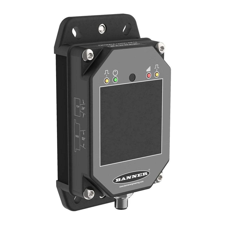
1 meter (3.3 feet). Typical moving targets can be detected as close as 0.4 meters (1.3 feet). Figure 1. Sensing Range 1.3 Banner Radar Configuration Software Use the Banner Radar Configuration software and Pro Converter Cable to set up the R-GAGE sensor. www.bannerengineering.com/us/en/products/sensors/software/radar-configuration.html For more information visit 1.4 Features and Indicators... - Page 5 ® R-GAGE Q130RA Sensor LED Status Description Signal Strength Output 1/2 There is no detectable object within the switch point distance that is Normally Open = Off returning a signal greater than the minimum signal strength threshold of Normally Closed = On one.
-
Page 6: Installation Instructions
3. Check the device alignment. This is done via the red Signal Strength LED or the Banner Radar Configuration Software. 4. Tighten the mounting screws to secure the device (or the device and the bracket) in the aligned position. - Page 7 2. Navigate to and open the downloaded file. 3. Click Install to begin the installation process. 4. Depending on your system settings, a popup window may appear prompting to allow Banner Radar Configuration to make changes to your computer. Click Yes.
-
Page 8: Getting Started
7. Click OK. The Connection screen closes and the sensor data displays. 3.2 Software Overview Easy setup and configuration of range, sensitivity, and output using the Banner Radar Configuration and Pro Converter Cable. Figure 4. Banner Radar Configuration Software 1. Navigation toolbar—Use this toolbar to connect to the sensor, to save or load a configuration, or to reset to factory defaults 2. -
Page 9: Banner Radar Configuration Workspace
Stop in the Live Sensor Data controls to enable Save Config. (Click Play to resume live data sampling.) Exit Exit the Banner Radar Configuration Software. From the Sensor menu, the following options are available: Connect Connect to the sensor. Disconnect Disconnect from the sensor. -
Page 10: Summary Pane
® R-GAGE Q130RA Sensor 4.3 Summary Pane The Summary pane (blue shaded area) displays Distance, Signal Strength, and Output Status. Distance Displays the distance to the target. Signal Strength Displays the amount of excess gain of the signal received from the target. The excess gain is relative to the minimum detection threshold (Signal Strength Threshold = 1). -
Page 11: Live Sensor Data Controls
® R-GAGE Q130RA Sensor 4.5 Live Sensor Data Controls After connecting to the sensor, data sampling begins automatically (but not recording). To stop data sampling, click Stop. This is required to load/save a configuration. To restart data sampling, click Play. This only samples data from the sensor and displays it on the plot; it does not record the data to a log file. -
Page 12: Remote Input
Enable/Disable Remote Teach Figure 6. Remote Input Map Note: If a factory reset is performed through the Banner Radar Configuration Software, the remote input wire becomes disabled (factory default setting). If the sensor is returned to factory defaults by using the remote input wire, the input wire remains enabled and the rest of the settings are restored to factory defaults. -
Page 13: Remote Setup
® R-GAGE Q130RA Sensor Action Result The green power LED flashes, alternating with the amber Output LEDs. Teach Accepted The sensor flashes the green power LED three times, then exits remote teach and Single-pulse the remote input. returns to run mode. Teach Not Accepted The green Power and red Signal Strength LEDs alternate flashing and the switch point... -
Page 14: Set The Sensitivity
® R-GAGE Q130RA Sensor 5.3 Set the Sensitivity Use Sensitivity Selection to set the signal strength threshold. 1. Access Sensitivity Selection. Action Result Triple-pulse the remote input. The green power LED flashes slowly. 2. Select the desired signal threshold. Action Result Pulse TEACH Mode... -
Page 15: Reset The Sensor To Factory Defaults
Reset the sensor to factory default settings using one of two methods. Note: If a factory reset is performed through the Banner Radar Configuration Software, the remote input wire becomes disabled (factory default setting). If the sensor is returned to factory defaults by using the remote input wire, the input wire remains enabled and the rest of the settings are restored to factory defaults. -
Page 16: Specifications
ETSI/EN 300 440 Output Low ≤ 2.5 V FCC ID: UE3RGAGE1XX for others, contact Banner Engineering Country of Origin: USA Output Protection Protected against short circuit conditions 7.1 FCC Part 15 and CAN ICES-3 (B)/NMB-3(B) This device complies with part 15 of the FCC Rules and CAN ICES-3 (B)/NMB-3(B). Operation is subject to the following two conditions: This device may not cause harmful interference, and This device must accept any interference received, including interference that may cause undesired operation. -
Page 17: Pc Requirements
Hard Drive Space USB Port 130MB Available USB port Important: Administrative rights are required to install the Banner Radar Configuration software. 7.3 Beam Patterns Note: The effective beam pattern depends on the signal strength threshold and the properties of the target. - Page 18 ® R-GAGE Q130RA Sensor Typical Beam Pattern (with BRTR-CC20E Radar Target, Typical Beam Pattern (with 4 different targets) with Signal Radar Cross Section = 50 m Strength Threshold = 1 Up-Down Beam Pattern Up-Down Beam Pattern 20 m 20 m Target 4 10 m 10 m...
- Page 19 ® R-GAGE Q130RA Sensor 7.3 Model -9076 Typical Beam Pattern (with BRTR-CC20E Radar Target, Typical Beam Pattern (with 4 different targets) with Signal Radar Cross Section = 50 m Strength Threshold = 1 Left-Right Beam Pattern Left-Right Beam Pattern 20 m 20 m Target 4 Target 1...
-
Page 20: Dimensions
® R-GAGE Q130RA Sensor 7.4 Dimensions All measurements are listed in millimeters [inches], unless noted otherwise. www.bannerengineering.com - Tel: + 1 888 373 6767... -
Page 21: Windows
® R-GAGE Q130RA Sensor 8 Windows The R-GAGE sensor can be placed behind a glass or a plastic window, but the configuration must be tested and the distance from the sensor to the window must be determined and controlled prior to installation. There is typically a 20% signal reduction when the sensor is placed behind a window. -
Page 22: Update The Software
1, above, to update the Software. 3. Navigate to and open the file BannerRadarConfigInstaller.exe. 4. Depending on your system settings, a popup window may appear prompting to allow Banner Radar Configuration Software to make changes to your computer. Click Yes. -
Page 23: Accessories
® R-GAGE Q130RA Sensor 10 Accessories 10.1 Configuration Tool MQDC-506-USB • Pro Converter Cable • 1.83 m (6 ft) M12/Euro-style quick disconnect to Device and USB to PC • Required for connection to Pro Editor 10.2 Quick Disconnect (QD) Cordsets 5-Pin Threaded M12/Euro-Style Cordsets—with Shield Model Length... - Page 24 ® R-GAGE Q130RA Sensor SMBWSQ120 • Rear-Mount Protective Metal Enclosure • Supports both horizontal and vertical sensor mounting • Required if the R-GAGE is exposed to rain or snow • Prevents buildup of water or ice from interfering with sensor performance www.bannerengineering.com - Tel: + 1 888 373 6767...
-
Page 25: Product Support And Maintenance
Banner and its affiliates and channel partners do not warrant that the services are secure, free from bugs, viruses, interruption, errors, theft or destruction. - Page 26 Index on delay 10 software 4, 22 output filtering 10 delay output LED 4 off 10 output status 10 on 10 total response time 10 distance 10 PC requirements 17 power LED 4 X range 9 hysteresis 10 range NC 10 Y range 9 NO 10 normally closed 10...
Need help?
Do you have a question about the R-GAGE Q130RA Series and is the answer not in the manual?
Questions and answers