Table of Contents
Advertisement
Quick Links
iVu Plus TG
Gen2
Quick Start Guide
Introduction
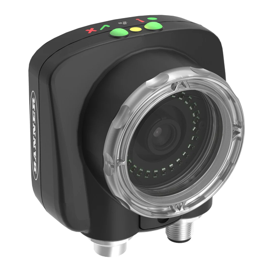
The iVu Plus TG Gen2 Series Sensor is used to monitor labels, parts, and packaging for type, size, orientation, shape, and
location. The sensor has an integrated or remote color touch screen display making installation, setup and configuration
easy without requiring a PC.
Start
Install and Connect the
Sensor
Initial Boot into Demo Mode
Select Sensor Type
Acquire A Good Image
Set Sensor Parameters
Finish
WARNING: Not To Be Used for Personnel Protection
Never use this device as a sensing device for personnel protection. Doing so could lead to
serious injury or death. This device does not include the self-checking redundant circuitry necessary
to allow its use in personnel safety applications. A sensor failure or malfunction can cause either an
energized or de-energized sensor output condition.
CAUTION: Electrostatic Discharge
Avoid the damage that electrostatic discharge (ESD) can cause to the Sensor.
Always use a proven method for preventing electrostatic discharge when installing a lens or attaching a
cable.
Installing and Connecting the Sensor
The iVu Plus TG sensor requires a bracket for mounting. Three brackets are available from Banner. The brackets allow the
sensor to be mounted either perpendicular to the part or at an adjustable angle.
Thread three M4 x 4mm screws through the bracket into the mounting holes in the bottom of the sensor. Tighten all three
screws.
Original Document
178442 Rev. B
Series Sensor
Quick Start Overview
This guide is designed to help you set up and install the iVu Plus TG. It
provides an overview of the sensor and illustrates how to set up the sensor
to inspect a label, part, or packaging. The flow chart to the left provides an
overview of the process.
Use of this document assumes familiarity with pertinent industry standards
and practices.
For complete information on programming, performance, troubleshooting,
dimensions, and accessories, please refer to the documentation listed below.
This documentation is available on the Product CD or at
www.bannerengineering.com. Search for the part number to view the
documentation.
•
iVu Plus TG Gen2 with Integrated Display (datasheet; P/N 179044)
•
iVu Plus TG Gen2 with Remote Display (datasheet; P/N 179045)
•
iVu Plus TG Gen2 Instruction Manual (P/N 179042)
•
iVu Plus Industrial Ethernet User's Guide (P/N B_3095133)
In addition, the sensor includes integrated Help.
9 September 2014
178442
Advertisement
Table of Contents

Related Manuals for Banner iVu Plus TG Gen2 Series


Summary of Contents for Banner iVu Plus TG Gen2 Series
- Page 1 Quick Start Guide Introduction The iVu Plus TG Gen2 Series Sensor is used to monitor labels, parts, and packaging for type, size, orientation, shape, and location. The sensor has an integrated or remote color touch screen display making installation, setup and configuration easy without requiring a PC.
- Page 2 Plus TG Gen2 Series Sensor Table 1: iVu Brackets SMBIVURAL SMBIVURAR SMBIVUU Cable Connections for Integrated Display The cable connections on the iVu Plus with integrated display are shown below, and power I/O connections (C) are defined in the Power I/O Connections table below.
-
Page 3: Demo Mode
Plus TG Gen2 Series Sensor Cable Connections for Remote Display The cable connections on the iVu Plus with remote display are shown below, and power I/O connections (B) are defined in the Power I/O Connections table below. Remote Display Connector... -
Page 4: Sensor Types
Plus TG Gen2 Series Sensor NOTE: Switch between Live Mode and Demo Mode any time by going to Main Menu > System > Mode. Sensor Types Area Sensor An Area type sensor is used to ensure that a feature, or multiple features, are present on a part. When setting up the sensor for an Area inspection, a feature, such as a drilled hole, is identified as well as the size (area) expected. -
Page 5: Icon Reference
Plus TG Gen2 Series Sensor Live Inspection System Mode Demo ROI and Mask Sensors Area Save to USB Configuration Intensity Range Load from USB Area Range Sensor Type selection determines Reset to Defaults first menu item under inspection Pass Count... - Page 6 Plus TG Gen2 Series Sensor Icon Description The Imager menu icon is on the Main Menu, and lists parameters that affect the characteristics of the captured image. The System menu icon is on the Main Menu, and is used to manage the sensor.
-
Page 7: Acquiring A Good Image
Plus TG Gen2 Series Sensor Icon Description The Rectangular Mask icon displays on the left side of the screen when a mask is selected. Press to cycle through and select a Circular, Elliptical, or Rectangular-shaped mask. Display Icons Icon... - Page 8 Plus TG Gen2 Series Sensor • Main Menu > Imager > Exposure 4. Go to Main Menu > Imager > Focus to adjust the focus while monitoring the Focus Number: Adjust the Focus on a Micro Video Lens Model 1.
- Page 9 Plus TG Gen2 Series Sensor Micro Video Lens Models Lens Focusing Window Locking Clip Locking Screw Filter Cap (optional) Filter (optional) NOTE: Filter Kits are available separately. Adjust the Focus on a C-Mount Lens Model 1. Remove the Lens Enclosure.
-
Page 10: Multiple Inspections
Plus TG Gen2 Series Sensor Multiple Inspections The iVu Plus supports multiple inspections that facilitate storing and controlling up to 30 inspections of different Sensor Types. Adding a New Inspection To Add a new stored inspection: 1. Go to Main Menu > Inspection > Stored Inspections and click Add New. -
Page 11: Ivu Plus Communication Summary Of Ethernet And Serial
Plus TG Gen2 Series Sensor 2. Select the inspection to start and click the Start Running button that appears below it. iVu Plus Communication Summary of Ethernet and Serial The iVu Plus communicates with other devices via Ethernet or a UART serial communications port (RS-232). In order to establish an Ethernet connection to the sensor, the external device must be configured with the correct IP address and TCP port to communicate. -
Page 12: Banner Engineering Corp Limited Warranty
Banner Engineering Corp Limited Warranty Banner Engineering Corp. warrants its products to be free from defects in material and workmanship for one year following the date of shipment. Banner Engineering Corp. will repair or replace, free of charge, any product of its manufacture which, at the time it is returned to the factory, is found to have been defective during the warranty period.
Need help?
Do you have a question about the iVu Plus TG Gen2 Series and is the answer not in the manual?
Questions and answers