Table of Contents
Advertisement
Quick Links
iVu Plus BCR Gen2 Series Sensor
Quick Start Guide
Introduction
This guide is designed to help you set up and install the iVu Plus Barcode Reader (BCR) Gen2 Series Sensor. For complete information on
programming, performance, troubleshooting, dimensions, and accessories, please refer to the Instruction Manual at
Search for p/n 179047 to view the Instruction Manual. Use of this document assumes familiarity with pertinent industry standards and practices.
The iVu BCR includes integrated Help.
Program, modify and view inspections through the integrated touch screen, remote touch screen or Vision Manager PC software. Vision Manager is
not required to configure or run the iVu BCR.
Connect to the iVu BCR using Vision Manager PC Software to control the device remotely. After connecting to the device, the interface displays on
the Sensor tab. Use the interface in the same manner as the iVu BCR display.
WARNING: Not To Be Used for Personnel Protection
Never use this device as a sensing device for personnel protection. Doing so could lead to serious injury or death. This device
does not include the self-checking redundant circuitry necessary to allow its use in personnel safety applications. A sensor
failure or malfunction can cause either an energized or de-energized sensor output condition.
CAUTION: Electrostatic Discharge
Avoid the damage that electrostatic discharge (ESD) can cause to the Sensor.
Always use a proven method for preventing electrostatic discharge when installing a lens or attaching a cable.
Features and Indicators
Note: Integrated display models: The touchscreen display has a plastic cover to protect the display. Remove this cover when
configuring the device. When the display is not in use, keep the display covered to protect it.
Installation Instructions
Mount the iVu BCR
The iVu BCR requires a bracket for mounting. Brackets are available from Banner Engineering. See
the iVu BCR to be mounted either perpendicular to the part or at an adjustable angle.
1. Position the iVu BCR on the bracket.
2. Thread three M4 x 4 mm screws (supplied) through the bracket into the mounting holes in the bottom of the iVu BCR.
Original Document
178443 Rev. C
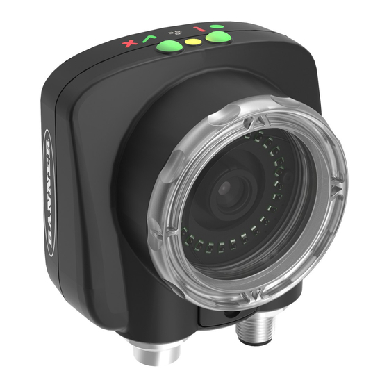
Figure 1. Features
Figure 2. Mounting Bracket Mounting Holes
10 October 2018
www.bannerengineering.com
1. Power LED
Green: Ready/Power
Red (blinking or steady): Error
2. Pass/Fail LED
Green (steady): Pass
Green (blinking): Error
Red: Fail
3. Ethernet I/O LED
Green: Connected
Off: Disconnected
4. Focusing Window
5. Focusing Window Locking Clip
6. Integrated Display (integrated display models
only)
www.bannerengineering.com
.
. The brackets allow
178443
Advertisement
Table of Contents

Related Manuals for Banner iVu Plus BCR Gen2 Series


Summary of Contents for Banner iVu Plus BCR Gen2 Series
- Page 1 Mount the iVu BCR www.bannerengineering.com The iVu BCR requires a bracket for mounting. Brackets are available from Banner Engineering. See . The brackets allow the iVu BCR to be mounted either perpendicular to the part or at an adjustable angle.
-
Page 2: Cable Connections
Plus BCR Gen2 Series Sensor 3. Tighten all three screws. 4. Mount the iVu BCR and bracket to the machine or equipment at the desired location. Do not tighten the mounting screws at this time. 5. Check the iVu BCR alignment. -
Page 3: Sensor Modes
Plus BCR Gen2 Series Sensor 1. Confirm the network connections. Click the Start button, then on the Start menu, click Control Panel. b) In Control Panel, click Network and Internet, then click Network and Sharing Center, and then click Change adapter settings. -
Page 4: Live Mode Overview
Plus BCR Gen2 Series Sensor Note: Switch between Live Mode and Demo Mode any time by going to Main Menu > System > Mode. Live Mode Overview The iVu BCR can be configured to evaluate one or more of the supported barcode types and can look for a specific number of barcodes from 1 to 10. - Page 5 Plus BCR Gen2 Series Sensor Barcode Type Inspection Barcode Barcode Count Data Compare Compare Set Data Scan Time Limit Properties Inspection Name Inspection ID Select Stored Inspections Add New Live Mode Startup System Demo Mode Mode Delete Set Name / ID...
-
Page 6: Display Icons
• Capture the barcode with lighting that optimizes its contrast and separates it from the background. Depending on the target, this may mean the integral ring light is not the best choice and other Banner lights should be considered. • Adjust the mounting angle to provide the clearest image of the barcode. The mounting bracket lets you easily position and adjust the iVu BCR. -
Page 7: Adjust The Focus On A Micro Video Lens Model
Plus BCR Gen2 Series Sensor 4. Go to Main Menu > Imager > Focus to adjust the focus while monitoring the Focus Number: Adjust the Focus on a Micro Video Lens Model 1. Use the supplied 1/16 inch hex key to loosen the focusing window locking screw (D), then adjust focus on the iVu BCR using the clear focusing window (B). -
Page 8: Setting Up A Barcode Application
Plus BCR Gen2 Series Sensor Note: The retainer ring (C) and filter (D) are optional. Filter kits are available separately. Setting Up a Barcode Application This section describes how to set up the iVu BCR sensor. 1. Go to Main Menu > Inspection > Barcode > Barcode Type . -
Page 9: Trigger Modes
Plus BCR Gen2 Series Sensor 2. Go to the Main Menu > Inspection > Barcode > Data Compare > Set Data, and click Show last read data. 3. Click Yes. 4. Click to return to the Home screen. For all subsequent triggers, when the sensor reads the barcode data, it compares it against this reference data. -
Page 10: Serial And Ethernet Output
Plus BCR Gen2 Series Sensor • Continuous Scan—the sensor uses internal timing to continuously capture images • External - Single—inspections are triggered in response to an electrical signal on the Trigger input line • External - Gated—the sensor continues to capture images and run barcode scans, while an external trigger input signal is active, until a successful Read occurs or until the External Trigger input signal becomes inactive •... -
Page 11: Multiple Inspections
Plus BCR Gen2 Series Sensor Scenario #1 Scenario #2 Scenario #3 Command Channels Ethernet Serial I/O Ethernet Serial I/O Ethernet Serial I/O Command Channel Industrial Ethernet Data Export Image Export Multiple Inspections The iVu BCR supports multiple inspections that facilitate storing and controlling up to 30 inspections of different types of barcodes. - Page 12 Banner Engineering Corp. Limited Warranty Banner Engineering Corp. warrants its products to be free from defects in material and workmanship for one year following the date of shipment. Banner Engineering Corp. will repair or replace, free of charge, any product of its manufacture which, at the time it is returned to the factory, is found to have been defective during the warranty period. This warranty does not cover damage or liability for misuse, abuse, or the improper application or installation of the Banner product.
Need help?
Do you have a question about the iVu Plus BCR Gen2 Series and is the answer not in the manual?
Questions and answers