HPE Synergy 12000 Frame Setup And Installation Manual
Hide thumbs
Also See for Synergy 12000 Frame:
- Setup and installation manual (101 pages) ,
- Maintenance and service manual (141 pages) ,
- Installation instructions (2 pages)
Table of Contents
Advertisement
HPE Synergy 12000 Frame Setup and
Installation Guide
Abstract
This document describes identification, installation, and setup for the HPE Synergy System. This guide is for
an experienced service technician. Hewlett Packard Enterprise assumes you are qualified in the servicing of
the HPE Synergy components and overall solution.
Part Number: 806424-005
Published: September 2019
Edition: 5
Advertisement
Table of Contents

Related Manuals for HPE Synergy 12000 Frame


Summary of Contents for HPE Synergy 12000 Frame
- Page 1 Installation Guide Abstract This document describes identification, installation, and setup for the HPE Synergy System. This guide is for an experienced service technician. Hewlett Packard Enterprise assumes you are qualified in the servicing of the HPE Synergy components and overall solution.
- Page 2 © Copyright 2016-2019 Hewlett Packard Enterprise Development LP Notices The information contained herein is subject to change without notice. The only warranties for Hewlett Packard Enterprise products and services are set forth in the express warranty statements accompanying such products and services. Nothing herein should be construed as constituting an additional warranty.
-
Page 3: Table Of Contents
HPE Synergy 50Gb Interconnect Link Module LEDs and buttons................34 HPE Synergy 50Gb Interconnect Link Module interconnect link ports..............35 HPE Virtual Connect SE 100Gb F8 Module for HPE Synergy LEDs and buttons..........35 HPE Virtual Connect SE 100Gb F32 Module for HPE Synergy components............39 HPE Virtual Connect SE 40Gb F8 Module for HPE Synergy LEDs and buttons........... - Page 4 HPE Synergy Console icons................................101 Issues during installation.......................................105 HPE Synergy Console......................................106 Accessing the HPE OneView Maintenance Console from the frame link module..........107 Connecting to the HPE OneView maintenance console using SSH................107 Creating a support dump file................................107 Resetting to factory settings....................................108 Resetting the appliance module to the original factory settings.................108...
- Page 5 HPE Synergy document overview (documentation map)........115 Specifications.........................116 HPE Synergy QuickSpecs......................................116 Electrostatic discharge....................117 Support and other resources..................118 Accessing Hewlett Packard Enterprise Support............................118 Accessing updates........................................118 Customer self repair.........................................119 Remote support.......................................... 119 Warranty information......................................119 Regulatory information......................................120 Documentation feedback...................................... 120...
-
Page 6: Planning The Installation
Site requirements Select an installation site that meets the detailed installation site requirements described in the site planning guide on the Hewlett Packard Enterprise website (http://www.hpe.com/info/synergy-docs). Warning, caution, and important messages WARNING: To reduce the risk of personal injury or damage to equipment, heed all warnings and cautions throughout the installation instructions. -
Page 7: Determine Power And Cooling Configurations
Tool helps plan and organize all Synergy options to build a single frame, multiple frame, or racks for a complete solution ready to order from HPE using a simple BOM from the tool. The Synergy Planning Tool can be found on the Hewlett Packard Enterprise Sales Portal website in the Tools section. -
Page 8: Space And Airflow Requirements
Space and airflow requirements CAUTION: In high-density configurations, the HPE 11000 G2 Series Rack Airflow Optimization Kit (BW930A) must be installed to prevent airflow from the rear of the rack to the front the rack through gaps in the rack frame. -
Page 9: Grounding Requirements
While the square-hole rail set is the standard option, either rail set supports a fully loaded frame weighing 550 lb (249.48 kg). Four of these frames together approach the 2,250 lb (1247.38 kg) internal IT equipment limit of both the HPE 42U x 600 mm x 1075 mm and the 42U 600 mm x 1200 mm 11000G2 Series QS racks. -
Page 10: Hpe Synergy Configuration
Never place the frame on a surface that cannot support up to 249.50 kg ( 550.00 lb). HPE Synergy configuration An initial setup for HPE Synergy requires software release planning and planning the location for each component. To ensure a proper configuration, review the information in the following documents on the Hewlett Packard Enterprise website (http://www.hpe.com/info/synergy-docs):... - Page 11 Item Name Description HPE Synergy 12000 Frame The frame for installing HPE Synergy components. Front panel The front panel ports of the frame for KVM connection. Appliance module blank A mandatory insert installed in any unused appliance module bay. Appliance module A hardware appliance for embedded management.
- Page 12 Installation instructions for compute modules, options, The printed installation instructions for HPE and interconnects Synergy components. HPE Synergy 12000 Frame Rack Template The printed template for locating the positions of frames, rack rails, and cage nuts in a rack. Quantity as ordered...
-
Page 13: Component And Led Identification
Component and LED identification Information pull tabs Pull tabs on the HPE Synergy frame front and rear provide system information. Figure 1: Information pull tab locations Item Description The front pull tab (top left) has the frame product ID, serial number, and the device bay numbering for the frame front bays. -
Page 14: Mobile-Ready Content
Mobile QR code locations Mobile QR codes are located on HPE Synergy components and pull tabs and provide quick and efficient access to product specific content for the component. The QR codes takes you to a page that allows you to browse to the online documentation by choosing an HPE Synergy component. -
Page 15: Device Bay Numbering
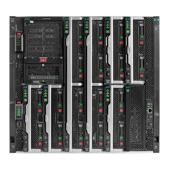
Item Description Device bays—Compute modules and storage modules. Front panel—Provides access to the HPE Synergy Console, through KVM or laptop. Appliance bays. Device bay numbering All device bays in the frame are numbered in consecutive order from lowest to highest, from left to right from top to bottom, as observed by a user looking directly at the frame. - Page 16 Device bay partitions Vertical frame partitions There are two vertical partitions between device bays in the frame. These nonremovable partitions provide structural integrity to the frame as well as mechanical attach points for the horizontal shelf that divide a full-height bay into two half-height bays.
-
Page 17: Front Panel Components
Figure 5: Optional horizontal half-shelf Front panel components Component and LED identification... -
Page 18: Appliance Module Leds And Components
Appliance module LEDs and components Appliance module LEDs and components are the same for both an HPE Synergy Composer (1st gen) and an HPE Synergy Image Streamer. HPE Synergy Composer2 looks slightly different but has the same LED and components on the front panel. - Page 19 Figure 6: HPE Synergy Composer (1st gen) and an HPE Synergy Image Streamer (left) and HPE Synergy Composer2 (right) Item Description Function UID LED • Solid blue — Illuminates to locate the appliance module. • Flashing blue — Indicates appliance module firmware update. Do not power off or remove appliance module when the UID LED is flashing.
- Page 20 Item Description Function Power LED Indicates power to the appliance module. • Off — No power. Verify that the appliance module is fully inserted into the frame link module. • Flashing amber — The appliance module is initializing. • Solid amber — The appliance module is powered off. •...
-
Page 21: Compute Module Leds And Buttons
Off = Deactivated Health status LED Solid green = Normal Flashing green (1 Hz/cycle per sec) = HPE iLO is rebooting Flashing amber = System degraded Flashing red (1 Hz/cycle per sec) = System critical Mezzanine NIC status LED... - Page 22 If all other LEDs are off, then no power is present to the compute module. If the health LED is flashing green while the system power LED is off indicates that the Power On/Standby button service is initializing or that an iLO reboot is in progress. Facility power is not present, power cord is not attached, no power supplies are installed, power supply failure has occurred, or the power button cable is disconnected.
-
Page 23: Storage Module Leds
• Solid indicates that the LED remains in the on state. • Flashing indicates that the LED is on for 2 seconds and off for 1 second. • Fast-flashing indicates that the LED is on for 300 ms and off for 300 ms. State Definition NVDIMM-N Function LED... -
Page 24: Frame Rear Components
Item Status Definition Flashing amber Thermal warning, close the drive drawer Solid blue One or more drives are being located Flashing blue Firmware flash in progress No drives are being located Health status Green Normal operation Flashing amber Degraded condition Flashing red Critical condition Drive status (in priority... -
Page 25: Rear Component Bay Numbering
Item Description Fans (10) Interconnect modules (up to 6) Power supplies (6) Frame link modules (2) Rear component bay numbering Components Bays Labels 1 and 2 Frame link modules 1 and 4 Interconnect modules These interconnect modules are redundant pairs on fabric 1. 2 and 5 Interconnect modules These interconnect modules are redundant... -
Page 26: Hpe Synergy 4-Port Frame Link Module Components And Leds
NOTE: The arrow direction on each of the power supply icons indicates the recommended power routing to either A-side or B-side. For more information about A-side and B-side power distribution, see the HPE Synergy Cabling Guide in the Hewlett Packard Enterprise Information Library (http://www.hpe.com/info/synergy-cabling-guide). - Page 27 Flashing blue = Firmware upgrade is in progress on the frame link module. Do not remove either frame link module while the UID LED is flashing. USB adapter thumbscrew For securing an HPE Synergy 4-Port Frame Link Module USB Adapter to the HPE connection Synergy 4-Port Frame Link Module.
- Page 28 • Flashing amber = Warning • Flashing red = Critical error If the Health LED indicates a warning or a critical error, connect to HPE OneView or to the HPE Synergy Console for more information and troubleshooting assistance. LINK port...
-
Page 29: Hpe Synergy Frame Link Module Components And Leds
• Flashing amber = Warning • Flashing red = Critical error If the Health LED indicates a warning or a critical error, connect to HPE OneView or to the HPE Synergy Console for more information and troubleshooting assistance. Table Continued... - Page 30 USB port Allows connection to the frame using a supported USB device. Devices include a keyboard or mouse for connecting to the HPE Synergy Console. To connect multiple devices, a USB hub (not included) is required. Used for performing a USB recovery frame link module firmware update.
-
Page 31: Power Supply Led
Power supply LED Power LED Condition No input power to the power supply or power supply failure. Connect to the HPE Synergy console and check for power supply error messages. Solid green Normal operation Flashing amber Warning. Connect to HPE OneView Hardware Setup to troubleshoot. -
Page 32: Hpe Synergy 10Gb Interconnect Link Module Leds And Buttons
HPE Synergy 10Gb Interconnect Link Module LEDs and buttons Item Description Status Health LED Solid green = Normal Solid amber = No power present Flashing amber = Module degraded Solid red = Installation alignment error. UID button/LED Solid blue = Activated by OneView... -
Page 33: Hpe Synergy 20Gb Interconnect Link Module Leds And Buttons
HPE Synergy 20Gb Interconnect Link Module LEDs and buttons Item Description Status Health LED Solid green = Normal Solid amber = No power present Flashing amber = Module degraded Solid red = Installation alignment error. UID button/LED Solid blue = Activated by OneView... -
Page 34: Hpe Synergy 20Gb Interconnect Link Module Interconnect Link Ports
Remove and then reinstall the module. HPE Synergy 20Gb Interconnect Link Module interconnect link ports Use an interconnect link cable when linking ports L1 or L2 to a master interconnect module. HPE Synergy 50Gb Interconnect Link Module LEDs and buttons... -
Page 35: Hpe Synergy 50Gb Interconnect Link Module Interconnect Link Ports
NOTE: If you are running 25 Gb speeds, you only need one cable. If you are running 50 Gb speeds, you must connect two cables. If you are connecting two cables, you must populate L1 first. HPE Virtual Connect SE 100Gb F8 Module for HPE Synergy LEDs and buttons Component and LED identification... - Page 36 Item Description Status Interconnect link port LEDs Solid green = Linked Solid red = Error detected Off = No link QSFP28 uplink port LEDs If the port is in 40GbE or 100GbE mode, only the leftmost LED lights up when linked. The four LEDs above each port correspond to the 10/25GbE or 8Gb/16Gb/ 32Gb FC channels of the port.
- Page 37 Item Description Status • Flashing magenta = ◦ 40Gb Ethernet link with activity ◦ 16Gb FC link with activity • Solid cyan = ◦ 100Gb Ethernet link without activity ◦ 32Gb FC link without activity • Flashing cyan = ◦ 100Gb Ethernet link with activity ◦...
- Page 38 Solid blue = Activated Flashing blue = Firmware upgrade in progress Off = Deactivated See HPE OneView (http://www.hpe.com/info/oneview/docs) When illuminated, the QSFP28 port LEDs indicate the port operating states for each of the uplink ports in the selected mode. Component and LED identification...
-
Page 39: Hpe Virtual Connect Se 100Gb F32 Module For Hpe Synergy Components
SFP+ uplink ports X1-X2 For Image Streamer Micro-USB For Serial Port (115200,8,1) USB 3.0 port (unused) QSFP28 uplink ports Q7– For Ethernet stacking links HPE Virtual Connect SE 40Gb F8 Module for HPE Synergy LEDs and buttons Component and LED identification... - Page 40 Item Description Status Solid green = Linked Interconnect link port LEDs Solid red = Error detected Off = No link The four LEDs above each port correspond to the 10GbE or 8Gb FC QSFP+ port LEDs channels of the port. The LEDs display one of four modes: Ethernet mode: •...
-
Page 41: Hpe Virtual Connect Se 40Gb F8 Module For Hpe Synergy Components
See OneView (http://www.hpe.com/info/oneview/docs) Remove and then reinstall the module. When illuminated, QSFP+ port LEDs indicate the port operating states for each of the uplink ports in the selected mode. HPE Virtual Connect SE 40Gb F8 Module for HPE Synergy components Item Component Description Interconnect link ports L1–... -
Page 42: Hpe Synergy 40Gb F8 Switch Module Leds And Buttons
HPE Synergy 40Gb F8 Switch Module LEDs and buttons Component and LED identification... - Page 43 Item Description Status Solid green = Linked Interconnect link port LEDs Solid red = Error detected Off = No link The four LEDs above each port correspond to the 10GbE or 8Gb FC QSFP+ port LEDs channels of the port. The LEDs display one of four modes: Ethernet mode: •...
-
Page 44: Hpe Synergy 40Gb F8 Switch Module Components
Solid green = FC mode is selected. See OneView (http://www.hpe.com/info/oneview/docs) Remove and then reinstall the module. When illuminated, QSFP+ port LEDs indicate the port operating states for each of the uplink ports in the selected mode. HPE Synergy 40Gb F8 Switch Module components Item Component Description Interconnect link ports L1–... -
Page 45: Mellanox Sh2200 Switch Module For Hpe Synergy Leds And Components
Mellanox SH2200 Switch Module for HPE Synergy LEDs and components Item Description Serial port QSFP+ uplink ports (8) UID LED Solid blue = Activated Flashing blue = Firmware upgrade in progress. Off = Deactivated Health LED Off = No power present... -
Page 46: Installation
Installation Installing the Synergy system components Procedure 1. Unpack the system. 2. Remove components from the frame. 3. For rack-free installations, set up the frame on an appropriate surface, and then install the frame options. 4. For rack installations, install the frame into the rack, and then install the frame options. 5. -
Page 47: Installing The Frame In A Rack-Free Environment
For specific instructions concerning removing the components, see the HPE Synergy 12000 Frame Maintenance and Service Guide. Installing the frame in a rack-free environment WARNING: To reduce the risk of personal injury or damage to the equipment in a rack-free environment: •... -
Page 48: Measuring With The Rack Template
Measuring with the rack template The HPE Synergy 12000 Frame Rack Template ships with the frame. The rack template provides detailed instructions on where to position the frame and rack rails, and where to install the cage or clip nuts. Each frame kit includes the rack rails recommended for that frame. - Page 49 Procedure 1. Begin with the left rack rail. Shorten the rail. 2. Align the rear end of the rail with the rack rear column. 3. Position the rail tabs next to the square openings in the rack rear column. 4. Keeping the rail level, insert the rear rail tabs into the rack rear column, and push the tabs down into place. 5.
-
Page 50: Installing The Rack Rails For A Round-Hole Rack
8. Repeat the procedure for the right rack rail. The installation is complete. Installing the rack rails for a round-hole rack Procedure 1. Align and install the rails in the rack. 2. Repeat the procedure for the other rail. To remove the rails, reverse the installation procedure. Installation... -
Page 51: Installing The Frame Into The Rack
Installing the frame into the rack WARNING: When lifting the frame with the optional removable handles, always use at least four people to lift the frame into the rack. If the frame is being loaded into the rack above chest level, a fifth person must assist with aligning the frame with the rails while the other four people support the weight of the frame. - Page 52 3. Slide the frame into the rack until the rear lift handles are close to the rack. While still supporting the frame with the front lift handles, remove the rear lift handles from each side of the frame, and then slide the frame halfway into the rack.
- Page 53 5. Remove the left and right frame bezels from front of the frame by inserting your finger in the hole at the bottom of the frame bezel and pull out and up, then pull the top of the frame bezel away from the frame. 6.
-
Page 54: Component Installation
After all components are installed and cabled, be sure to reimage the appliance module before bringing the appliance module into your HPE Synergy configuration. Updating the firmware, ensures that the appliance module is compatible with the HPE Synergy Software Release installed on HPE Synergy. For more information, see Update the firmware on page 96. -
Page 55: Configuring The Device Bays
2. Install the first appliance module into appliance bay 1. When the appliance module is fully seated, it locks into place. Configuring the device bays You have to add or remove the shelves depending on the type of compute modules that you are installing in the frame. Creating a full-height module bay blank Procedure 1. - Page 56 • If you are using a module bay blank that came with the frame, the coupler plate can be found with the contents of the full-height device shipping box. • If you are using a device bay blank that you purchased as an option, remove the coupler plate from inside the blank.
- Page 57 Removing a device bay shelf Procedure 1. Press and hold the release latches to release the locking mechanism. 2. Slide the removable shelf out of the frame. Installing a device bay shelf The frame has a slot and notch on the device bay walls that is used to guide the shelf when inserted. Procedure 1.
- Page 58 3. When the shelf is fully inserted, release the latches to lock the shelf in place. Removing the half shelf Prerequisites If installed, remove the full-height compute module from the adjacent bay before removing and replacing the half shelf. Procedure 1.
- Page 59 Replacing the half shelf Procedure 1. Align the spools to the keyhole slots in the frame. 2. Insert the spools into the keyhole slots and slide the half shelf towards the rear of the frame until it locks into place. Installation...
- Page 60 Installing the half shelf Procedure 1. Align the spools to the keyhole slots in the frame. 2. Insert the spools into the keyhole slots and slide the half shelf towards the rear of the frame until it locks into place. Installation...
-
Page 61: Installing Compute Modules
• Installing a full-height compute module The HPE Synergy 12000 Frame ships with three device bay shelves installed to support a 12 half-height compute module configuration. To install a full-height compute module, remove the device bay shelves and corresponding blanks. - Page 62 2. Remove the device bay shelf. NOTE: Keep the compute module end caps, blanks, and device bay shelves for future use. 3. Remove the compute module end cap. 4. Prepare the compute module for installation by opening the compute module handle. Installation...
- Page 63 5. Install the compute module. Press the compute module handle near each release button to completely close the handle. CAUTION: To prevent improper cooling and thermal damage, do not operate the compute module or the frame unless all device bays are populated with either a component or a blank. 6.
- Page 64 2. If required, install the device bay shelf. NOTE: Keep the compute module end caps, blanks, and device bay shelves for future use. 3. Remove the compute module end cap. 4. Prepare the compute module for installation by opening the compute module handle. Installation...
-
Page 65: Installing A Frame Link Module
5. Install the compute module. Press the compute module handle near the release button to completely close the handle. Installing a frame link module Procedure 1. If installed, remove the frame link module blank from the frame link module bay in the rear of the frame. CAUTION: Use caution when installing the frame link module into the frame to avoid damage to the connector. -
Page 66: Installing The Storage Module
Installing the storage module Prerequisites CAUTION: Installation of the storage module into the frame without drives requires one person. Installation of the storage module into the frame with drives already installed requires two people. Be sure that you have the required number of people to lift the storage module into the frame. Procedure 1. -
Page 67: Installing Drives In The Storage Module
3. To add drives to the drive drawer, see Installing the drives in the storage module. More information Installing drives in the storage module on page 67 Installing drives in the storage module Procedure 1. Press the drive drawer release latch and pull out the drawer with the driver drawer release handle. 2. -
Page 68: Installing Fans
3. Install all drives. 4. Close the drive drawer. Installing fans All ten fans must be populated at all times. There is no required installation order for installing the fans. CAUTION: Use caution to avoid hitting the PCA card edge against the frame. Damage to the fan PCA could result in malfunction of the fan or the frame. -
Page 69: Installing Interconnect Modules
2. After power is applied to the frame, verify that each fan LED is green. Installing interconnect modules There are six single-wide interconnect bays in the frame. Installation in the interconnect bays depends on the type of mezzanine card installed in the compute module and in which mezzanine slot the mezzanine card was installed. IMPORTANT: If the mezzanine card is not installed properly or the interconnect module installation does not coincide with the mezzanine card installation, the ports on the interconnect module will not function. - Page 70 3. Remove the interconnect module end cap. 4. Install the interconnect module, and close the release lever. Installation...
- Page 71 Interconnect module configurations The HPE Synergy 12000 Frame supports a pair of redundant interconnect modules for each of the three fabrics. Hewlett Packard Enterprise recommends the following best practices: • Fabric 1 primary use—Storage • Fabric 2 primary use—Storage or networking •...
- Page 72 Synergy 12Gb SAS Connection Module is installed, it is supported only in fabric 1 and therefore, that fabric solution is the first priority for fabric 1. If the HPE Synergy 12Gb SAS Connection Module is not used, then fabric 1 is available to be used by one of the supported HPE Synergy Fibre Channel interconnect modules.
- Page 73 • HPE Synergy 40Gb F8 Switch Module • HPE Virtual Connect SE 100Gb F32 Module for HPE Synergy From one to four interconnect link modules are required to support the master interconnect module when using the following interconnect link modules: •...
- Page 74 Mezzanine to frame signal routing The HPE Synergy 12000 Frame midplane provides 4-lane high-speed signal routing from all 12 device bays to the 6 interconnect module bays. A pair of interconnects installed in an interconnect bay set provides redundant connectivity for each connected mezzanine card.
- Page 75 The location of a mezzanine option in the compute module dictates the location of the corresponding interconnect module in the rear of the frame. Half-height compute module mezzanine connector definitions NOTE: The compute module hood label includes the exact mezzanine card locations. Item Mezz slot connector identification Supported card types...
-
Page 76: Installing Power Supplies
5, processor 4 must be installed. Installing power supplies HPE Synergy supports several different types of HPE Synergy power supplies. For more information, see the HPE Synergy 12000 Frame Quick Specs on the Hewlett Packard Enterprise Information Library (http://www.hpe.com/info/qs). - Page 77 WARNING: To reduce the risk of electric shock or damage to the equipment, do not connect the power cord to the power supply until the power supply is installed. NOTE: When installed in the HPE Synergy 12000 Frame, the HPE 2900-3400W Hot Plug Platinum Power Supply only supports 230-240VAC input.
- Page 78 Sufficient power supplies must be installed to support the installed devices and interconnect modules. Power estimates for HPE Synergy can be provided using either the HPE Synergy Planning Tool or the HPE Power Advisor. For more information about the HPE Power Advisor or the HPE Synergy Planning Tool, see the Data Center Infrastructure Advisor page (https://dcia.itcs.hpe.com/).
-
Page 79: Installing A Dc Power Supply
Hole spacing – 0.63 in (16.00 mm) Prerequisites • Be sure the -48V DC power cables are installed. For more information, see the HPE Synergy 12000 Frame -48V DC Power Cable Installation Instructions. • Be sure that a ground connection to the HPE Synergy 12000 Frame has been properly installed. See Installing the DC power grounding kit or the document that ships with the kit. - Page 80 Using a torque-controlled T-25 screwdriver, tighten both screws to 15 lb-in of torque. Crimp a two-hole lug onto the return cable. Insert the two-hole lug through the aperture labeled "RTN" on the power supply input connector. Secure the two-hole lug to the RTN input connector terminal with two screws. 10.
- Page 81 13. Insert the power supply into the frame until it locks into place. The power supply is marked with TOP to ensure proper orientation during installation. 14. Connect the power cables to the -48V DC power source. 15. Turn on or enable the -48V DC power source. 16.
- Page 82 CAUTION: To prevent improper cooling and thermal damage, do not operate the frame unless all bays are populated with either a component or a blank. Installing the DC power grounding kit (no bracket) For clarity, the rack is not shown in the images of this procedure. Prerequisites The following tools are required to complete this procedure: •...
- Page 83 Installing the DC power grounding kit (with bracket) For clarity, the rack is not shown in the images of this procedure. Prerequisites The following tools are required to complete this procedure: • T-15 Torx screwdriver • 8 mm socket wrench Procedure 1.
-
Page 84: Cabling The Frame
WARNING: Be sure that all circuit breakers are locked in the off position before connecting any power components. Prerequisites Download and review the HPE Synergy Cabling Guide from the Hewlett Packard Enterprise Information Library ( http:// www.hpe.com/info/synergy-docs). Installation... - Page 85 3. Cable the interconnect modules. 4. Connect the power cables. Connect to the power source in your facility to each of the installed power supplies, and power up the frame. 5. To configure HPE Synergy, connect to the HPE Synergy Console. Installation...
-
Page 86: Hpe Synergy Cabling
HPE Synergy 12000 frames with HPE Synergy Image Streamer installed use each MGMT port in the frame for OS deployment. When HPE Synergy Image Streamer is installed in a frame, the MGMT ports are automatically dedicated to OS deployment and cannot be used for management network connectivity. -
Page 87: Configuring Hpe Synergy
Add a firmware bundle to the appliance module firmware repository. 4. Configure HPE Synergy Image Streamer. For more information, see "Quick Start: Initial configuration of HPE Synergy Image Streamer" in the HPE OneView Help for HPE Synergy at http://www.hpe.com/info/synergy-docs. -
Page 88: Hpe Synergy Console Connections
WARNING: Do not plug the front panel laptop port into a switch. The front panel laptop port is designed to provide a single laptop access to the HPE Synergy Console. Plugging the laptop port into a switch may cause issues on a network where DHCP is running. - Page 89 NOTE: This procedure describes connecting a keyboard and mouse to a monitor with an integrated USB hub. Alternatively, you can use a standalone USB hub to connect a keyboard and mouse. NOTE: Cabling to an HPE Synergy 4-Port Frame Link Modules requires an HPE Synergy 4-Port Frame Link Module USB Adapter Prerequisites A frame link module is installed in a frame link module bay.
- Page 90 • An HPE Synergy 4-Port Frame Link Module USB Adapter connected to an HPE Synergy 4-Port Frame Link module. 2. Connect a monitor to the frame with the monitor cable. 3. Connect a USB keyboard and mouse to the USB ports on the monitor, and connect the monitor USB to the frame with the USB cable.
- Page 91 Configuring HPE Synergy...
- Page 92 Active frame link module. This network address is used to manage the frame and is independent of the frame link module-specific addresses. NOTE: When adding remote frames (enclosures) to HPE OneView, use this link local IPv6 address. Frame Link Module Ports - Displays the frame link module MGMT and LINK port information for the Active and Standby frame link modules.
-
Page 93: Run Hardware Setup
Return to the Hardware Setup screen and look for additional issues until the Checklist indicates Setup complete. For more information about using HPE OneView, see the online help by clicking the question mark on the top bar of the HPE Synergy Console. -
Page 94: Remotely Connect To Hpe Oneview
Configure the interconnect module using the instructions provided with the interconnect module. c. To close the session, click the X in the top right corner. NOTE: To access the serial console for an interconnect module, connect to the HPE Synergy Console through ports in the same frame as the interconnect module. - Page 95 For detailed steps, see "Quick Start: Initial configuration of HPE OneView" in the HPE OneView Help for HPE Synergy (http://www.hpe.com/support/OV-InitialConfig). Create a network IMPORTANT: Define a SAN Manager before creating an FC or FCoE network. Create networks to define connections that route data across the IT infrastructure. You can create a single Ethernet , Fibre Channel, or FCoE network or multiple, tagged Ethernet networks at one time.
-
Page 96: Update The Firmware
If both appliance modules in a redundant pair are on the same firmware version, use HPE OneView to update to the latest firmware version. -
Page 97: Configure Additional Settings
For more information about configuring HPE Image Streamer, see the HPE OneView online help or the HPE OneView User Guide on the Hewlett Packard Enterprise website (http://www.hpe.com/info/synergy-docs). Configuring HPE OneView to deploy OS build artifacts to compute modules Once you add an Image Streamer OS deployment server in HPE OneView, you can launch the Image Streamer graphical user interface from the HPE OneView OS Deployment Servers screen. -
Page 98: Troubleshooting
Error screens when connecting to the HPE Synergy Console The following are some basic errors screens that may be encountered when connecting to the HPE Synergy Console. HPE Synergy Console not responding If the frame Composers are detected but not responding after 20 minutes, the following Attention screen appears, and prompts a Reset. - Page 99 Select Reset. HPE OneView resets and attempts again to boot the frame Composers. Troubleshooting...
-
Page 100: Frame Not Claimed By An Hpe Synergy Console
When the frame is not claimed by an HPE Synergy Console, the following Attention screen appears. To resolve, connect to the front panel display of a frame that contains an HPE Synergy Console. The HPE Synergy Console cannot connect to HPE OneView If the HPE Synergy Console cannot connect to HPE OneView, the following Attention screen appears. -
Page 101: Hpe Synergy Console Icons
1. Connect to the HPE Synergy Console through a different frame. 2. Reconnect to HPE OneView. 3. Verify there are no more than three live HPE OneView sessions within the management network. Any initiated sessions after three will not be able to connect to HPE OneView. - Page 102 • i icon — Select this icon to access the Information screen. The local frame information, including firmware version and discovered hardware components within the frame are displayed. Troubleshooting...
- Page 103 • Screen icon — Select this icon to access the hardware components discovered by the HPE Synergy Console, including Appliances, Interconnects, and Devices. Empty bays are represented by the grayed out "—" symbol, and components that are discovered but not managed by a serial port are grayed out and disabled.
- Page 104 • Serial console — To access the serial console: 1. Select one of the hardware components from the Screen icon to access the serial console for that component. Troubleshooting...
-
Page 105: Issues During Installation
2. Press Enter or another key on the keyboard to activate the console, if needed. Once activated, the console will begin to display data for the hardware component. • Keyboard shortcuts - These include: Keyboard shortcut Action Show or hide the top caption bar Ctrl + Zoom in Ctrl -... -
Page 106: Hpe Synergy Console
HPE Synergy Console When the HPE OneView user interface cannot be accessed, the HPE Synergy Console is available from a direct connection to the frame. The functions available in the console might require specific user credentials. -
Page 107: Accessing The Hpe Oneview Maintenance Console From The Frame Link Module
Creating a support dump file This procedure describes how to use the HPE Synergy maintenance console to create a support dump file from the local appliance (the appliance on which the HPE Synergy maintenance console runs) and store it on a USB drive. -
Page 108: Resetting To Factory Settings
IMPORTANT: Do not remove the USB drive until the operation is complete and the Synergy maintenance console advises that it is safe to remove the drive. 2. Use the appliance console to access the HPE Synergy maintenance console main menu. 3. Select Support dump. - Page 109 • If you do not have a backup file for HPE OneView, you will need to perform a factory reset on all the devices in the domain.
-
Page 110: Frame Link Module Factory Reset
10 minutes. If the frame link module is installed in a frame managed by HPE OneView, the frame link module will be reclaimed by HPE OneView after the factory reset is complete. -
Page 111: Performing A Frame Link Module Factory Reset
NOTE: The frame link module can be factory reset by pressing the front panel reset button until the front panel UID flashes or by using the HPE Synergy Console Actions menu. Hewlett Packard Enterprise recommends using the HPE Synergy Console to perform a factory reset. -
Page 112: Hpe Synergy Documentation Resources
HPE Synergy documentation resources The Hewlett Packard Enterprise Information Library (https://www.hpe.com/info/synergy-docs) provides a comprehensive, one stop location for all HPE Synergy documentation, including installation instructions, user guides, maintenance and service guides, best practices, and links to additional resources. The Library supports filtering to improve findability. -
Page 113: Hpe Synergy Firmware Update Resources
Information on how to update the firmware and recommended best practices to update Guide firmware and drivers through HPE OneView. The HPE Synergy Software Release Information site (http://www.hpe.com/info/synergy-sw-release-information) provides an interactive resource for firmware update information. HPE Synergy firmware update resources are also available within HPE OneView. HPE Synergy documentation resources... - Page 114 A list of HPE Synergy Management Combinations to use to compare HPE Synergy Custom SPPs supported by the selected HPE Synergy Management Combination. Firmware Feature Table A list of firmware features to use to compare HPE Synergy Custom SPPs supported by the selected HPE Synergy Management Combination. Upgrade Paths Table Information on HPE Synergy Composer and HPE Synergy Image Streamer upgrade paths and HPE Synergy Management Combinations.
-
Page 115: Hpe Synergy Document Overview (Documentation Map)
HPE Synergy 12000 Frame Setup and Installation • Product maintenance and service guides Guide • HPE OneView for HPE Synergy Firmware and Driver Update • Rack Rails Installation Instructions for the HPE Guide Synergy 12000 Frame (included with frame) •... -
Page 116: Specifications
Specifications HPE Synergy QuickSpecs HPE Synergy has system specifications as well as individual product and component specifications. For complete specification information, see the HPE Synergy and individual HPE Synergy product QuickSpecs on the Hewlett Packard Enterprise website (www.hpe.com/info/qs). Specifications... -
Page 117: Electrostatic Discharge
Electrostatic discharge Be aware of the precautions you must follow when setting up the system or handling components. A discharge of static electricity from a finger or other conductor may damage system boards or other static-sensitive devices. This type of damage may reduce the life expectancy of the system or component. -
Page 118: Support And Other Resources
Packard Enterprise Support Center More Information on Access to Support Materials page: www.hpe.com/support/AccessToSupportMaterials IMPORTANT: Access to some updates might require product entitlement when accessed through the Hewlett Packard Enterprise Support Center. You must have an HPE Passport set up with relevant entitlements. Support and other resources... -
Page 119: Customer Self Repair
HPE Proactive Care services www.hpe.com/services/proactivecare HPE Datacenter Care services www.hpe.com/services/datacentercare HPE Proactive Care service: Supported products list www.hpe.com/services/proactivecaresupportedproducts HPE Proactive Care advanced service: Supported products list www.hpe.com/services/proactivecareadvancedsupportedproducts Proactive Care customer information Proactive Care central www.hpe.com/services/proactivecarecentral Proactive Care service activation www.hpe.com/services/proactivecarecentralgetstarted... -
Page 120: Regulatory Information
Hewlett Packard Enterprise is committed to providing documentation that meets your needs. To help us improve the documentation, send any errors, suggestions, or comments to Documentation Feedback (docsfeedback@hpe.com). When submitting your feedback, include the document title, part number, edition, and publication date located on the front cover of the document. -
Page 121: Acronyms And Abbreviations
Acronyms and abbreviations Canadian Standards Association Customer Self Repair DHCP Dynamic Host Configuration Protocol electrostatic discharge International Electrotechnical Commission Integrated Lights-Out iLO 4 Integrated Lights-Out 4 PCIe Peripheral Component Interconnect Express power distribution unit RETMA Radio Electronics Television Manufacturers Association (rack spacing) RoHS Restriction of Hazardous Substances serial attached SCSI...
Need help?
Do you have a question about the Synergy 12000 Frame and is the answer not in the manual?
Questions and answers