HPE Synergy 12000 Frame Setup And Installation Manual
Hide thumbs
Also See for Synergy 12000 Frame:
- Setup and installation manual (121 pages) ,
- Maintenance and service manual (141 pages) ,
- Installation instructions (2 pages)
Table of Contents
Advertisement
HPE Synergy 12000 Frame Setup and
Installation Guide
Abstract
This document describes identification, installation, and setup for the HPE Synergy System.
This guide is for an experienced service technician. Hewlett Packard Enterprise assumes you
are qualified in the servicing of the HPE Synergy components and overall solution.
Part Number: 806424-003
Published: June 2018
Edition: 3
Advertisement
Table of Contents
Troubleshooting

Related Manuals for HPE Synergy 12000 Frame


Summary of Contents for HPE Synergy 12000 Frame
- Page 1 This document describes identification, installation, and setup for the HPE Synergy System. This guide is for an experienced service technician. Hewlett Packard Enterprise assumes you are qualified in the servicing of the HPE Synergy components and overall solution. Part Number: 806424-003...
- Page 2 © Copyright 2016-2018 Hewlett Packard Enterprise Development LP Notices The information contained herein is subject to change without notice. The only warranties for Hewlett Packard Enterprise products and services are set forth in the express warranty statements accompanying such products and services. Nothing herein should be construed as constituting an additional warranty. Hewlett Packard Enterprise shall not be liable for technical or editorial errors or omissions contained herein.
-
Page 3: Table Of Contents
Power requirements......................7 Space and airflow requirements....................8 Temperature requirements......................8 Grounding requirements....................... 9 Supported racks and rack options....................9 Rack-free environment requirements................10 HPE Synergy configuration......................10 Pallet contents..........................11 Component and LED identification............. 13 Information pull tabs........................13 Mobile-ready content......................14 Mobile QR code locations....................14 Frame front components and device bays..................14... - Page 4 Cabling power supplies for power feed redundancy............67 Cabling multiple frames for power feed redundant power..........68 Connect to the HPE Synergy Console..................69 Connecting to the HPE Synergy Console using a keyboard, video monitor, and mouse..........................70 Connecting to the HPE Synergy Console using a laptop computer.........71 Firmware....................
- Page 5 HPE Synergy troubleshooting resources..................92 Troubleshooting within HPE OneView................92 HPE Synergy Troubleshooting Guide................93 Error Message Guide for HPE ProLiant Gen10 servers and HPE Synergy..... 93 HPE OneView Help and HPE OneView API Reference...........93 HPE Synergy QuickSpecs....................93 HPE Synergy document overview (documentation map)....94 Specifications..................96...
-
Page 6: Planning The Installation
Site requirements Select an installation site that meets the detailed installation site requirements described in the site planning guide on the Hewlett Packard Enterprise website (http://www.hpe.com/info/synergy-docs). Warning, caution, and important messages WARNING: To reduce the risk of personal injury or damage to equipment, heed all warnings and cautions throughout the installation instructions. -
Page 7: Determine Power And Cooling Configurations
The Synergy Planning Tool helps plan and organize all Synergy options to build a single frame, multiple frame, or racks for a complete solution ready to order from HPE using a simple BOM from the tool. The Synergy Planning Tool can be found on the Hewlett Packard Enterprise Sales Portal website in the Tools section. -
Page 8: Space And Airflow Requirements
Space and airflow requirements CAUTION: In high-density configurations, the HPE 11000 G2 Series Rack Airflow Optimization Kit (BW930A) should be installed to prevent airflow from the rear of the rack to the front the rack via gaps in the rack frame. -
Page 9: Grounding Requirements
550 pounds. Four of these frames together approach the 2,250 pound internal IT equipment limit of both the HPE 42U x 600 mm x 1075 mm and the 42U 600 mm x 1200 mm 11000G2 Series QS racks. NOTE: The HPE Synergy 12000 Frame is deeper than the c7000 enclosure by approximately 3.5 inches. -
Page 10: Rack-Free Environment Requirements
Cables, PDUs, and other cable management hardware could increase the weight sufficiently to require the use of the HPE 42U x 600 mm x 1200 mm Intelligent Series QS rack, which supports 2,750 pound internal IT equipment. Rack-free environment requirements The HPE Synergy 12000 Frame (referred to as the frame) can be used in a rack-free environment. -
Page 11: Pallet Contents
Pallet contents Item Name Description HPE Synergy 12000 Frame The frame for installing Synergy components Front panel The front panel ports of the frame for KVM connection Appliance module blank A mandatory insert installed in any unused appliance module bay. - Page 12 Installation instructions for compute modules, The printed installation instructions for options, and interconnects Synergy components HPE Synergy 12000 Frame Rack Template The printed template for locating the positions of frames, rack rails, and cage nuts in a rack. Quantity as ordered...
-
Page 13: Component And Led Identification
Component and LED identification Information pull tabs Pull tabs on the HPE Synergy frame front and rear provide system information. Figure 1: Information pull tab locations Item Description The front pull tab (top left) has the frame product ID, serial number, and the device bay numbering for the frame front bays. -
Page 14: Mobile-Ready Content
Mobile QR code locations Mobile QR codes are located on HPE Synergy components and pull tabs and provide quick and efficient access to product specific content for the component. The QR codes takes you to a page that allows you to browse to the online documentation by choosing an HPE Synergy component. -
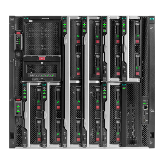
Page 15: Device Bay Numbering
Item Description Device bays—Compute modules and storage modules Front panel—Provides access to the HPE Synergy console, via KVM or laptop. Appliance bays Device bay numbering All device bays in the frame are numbered in consecutive order from lowest to highest, from left to right from top to bottom, as observed by a user looking directly at the frame. - Page 16 Device bay partitions Vertical frame partitions There are two vertical partitions between device bays in the frame. These nonremovable partitions provide structural integrity to the frame as well as mechanical attach points for the horizontal shelf that divide a full-height bay into two half-height bays. Up to six full-height device modules can be installed in a frame.
-
Page 17: Front Panel Components
Figure 5: Optional horizontal half-shelf Front panel components Front panel components... -
Page 18: Appliance Module Leds And Components
HPE Synergy Console use. To connect multiple devices, a USB hub (not included) is required. Appliance module LEDs and components Appliance module LEDs and components are the same for both an HPE Synergy Composer or an HPE Synergy Image Streamer. Appliance module LEDs and components... - Page 19 Activity LED Indicates which appliance module is active • Off—Indicates that the appliance module is the standby in a Highly Available configuration or HPE OneView is in an error state. • Solid green—Indicates that the appliance module is active. •...
- Page 20 Item Description Function Power LED Indicates power to the appliance • Off—No power. Verify that the appliance module is fully inserted into the frame link module. • Flashing amber—Appliance module is initializing. • Solid amber—Appliance module is powered off. • Solid green—Appliance module is powered on.
-
Page 21: Frame Rear Components
Frame rear components Item Description Fans (10) Interconnect modules (up to 6) Power supplies (6) Frame link modules (2) Rear component bay numbering Frame rear components... -
Page 22: Frame Link Module Components And Leds
Components Bays Labels Frame link modules 1 and 2 1 and 4 Interconnect modules These interconnect modules are redundant pairs on fabric 1. 2 and 5 Interconnect modules These interconnect modules are redundant pairs on fabric 2. 3 and 6 Interconnect modules These interconnect modules are redundant pairs on fabric 3. - Page 23 • Flashing red = Critical error If the Health LED indicates a warning or a critical error, connect to HPE OneView or to the HPE Synergy Console for more information and troubleshooting assistance. UID button Toggles the UID LED on or off.
-
Page 24: Power Supply Led
Power supply LED Power LED Condition No input power to the power supply or power supply failure. Connect to the HPE Synergy console and check for power supply error messages. Solid green Normal operation Flashing amber Warning. Connect to HPE OneView Hardware Setup to troubleshoot. -
Page 25: Fan Led
Fan LED LED color Fan status Solid green Normal operation Flashing red Critical. Connect to HPE OneView Hardware Setup to troubleshoot. Fan LED... -
Page 26: Installation
Installation Installing the Synergy system components Procedure 1. Unpack the system. 2. Remove components from the frame. 3. For rack-free installations, set up the frame on an appropriate surface, and then install the frame options. 4. For rack installations, install the frame into the rack, and then install the frame options. 5. -
Page 27: Installing The Frame In A Rack-Free Environment
For specific instructions concerning removing the components, see the HPE Synergy 12000 Frame Maintenance and Service Guide. Installing the frame in a rack-free environment WARNING: To reduce the risk of personal injury or damage to the equipment in a rack-free environment: •... -
Page 28: Measuring With The Rack Template
Measuring with the rack template The HP Synergy 12000 Frame Rack Template ships with the frame and provides detailed instructions on where to position the frame and rack rails, and where to install the cage or clip nuts. Each frame kit includes the rack rails recommended for that frame. - Page 29 Procedure 1. Begin with the left rack rail. Shorten the rail. 2. Align the rear end of the rail with the rack rear column. 3. Position the rail tabs next to the square openings in the rack rear column. 4. Keeping the rail level, insert the rear rail tabs into the rack rear column, and push the tabs down into place.
-
Page 30: Installing The Rack Rails For A Round-Hole Rack
8. Repeat the procedure for the right rack rail. The installation is complete. Installing the rack rails for a round-hole rack Procedure 1. Align and install the rails in the rack. 2. Repeat the procedure for the other rail. To remove the rails, reverse the installation procedure. Installing the rack rails for a round-hole rack... -
Page 31: Installing The Frame Into The Rack
Installing the frame into the rack WARNING: Always use at least four people to lift a frame into the rack. If the frame is being loaded into the rack above chest level, a fifth person must assist with aligning the frame with the rails while the other four people support the weight of the frame. - Page 32 3. Slide the frame into the rack until the rear lift handles are close to the rack. While still supporting the frame with the front lift handles, remove the rear lift handles from each side of the frame, and then slide the frame halfway into the rack.
- Page 33 5. Remove the left and right frame bezels from front of the frame by inserting your finger in the hole at the bottom of the frame bezel and pull out and up, then pull the top of the frame bezel away from the frame.
-
Page 34: Component Installation
After all components are installed and cabled, be sure to reimage the appliance module before bringing the appliance module into your HPE Synergy configuration. Updating the firmware, ensures that the appliance module is compatible with the HPE Synergy Software Release installed on HPE Synergy. For more information, see Firmware. -
Page 35: Installing Compute Modules
Install a half-height compute module Installing a full-height compute module The HPE Synergy 12000 Frame ships with three device bay shelves installed to support a 12 half-height compute module configuration. To install a full-height compute module, remove the device bay shelves and corresponding blanks. - Page 36 Procedure 1. Remove the blanks. 2. Remove the device bay shelf. NOTE: Keep the compute module end caps, blanks, and device bay shelves for future use. 3. Remove the compute module end cap. 4. Prepare the compute module for installation. 5.
- Page 37 6. Install the compute module. Press the compute module handle near each release button to completely close the handle. CAUTION: To prevent improper cooling and thermal damage, do not operate the compute module or the frame unless all device bays are populated with either a component or a blank. 7.
- Page 38 Creating a full-height module bay blank Procedure 1. Obtain the coupler plate: • If you are using a module bay blank that came with the frame, the coupler plate can be found with the contents of the full-height device shipping box. •...
- Page 39 4. Install the full-height blank into the device bay. Installing a half-height compute module Procedure 1. Remove the blank. 2. If required, install the device bay shelf. NOTE: Keep the compute module end caps, blanks, and device bay shelves for future use. 3.
- Page 40 4. Prepare the compute module for installation by opening the compute module handle. 5. Install the compute module. Press the compute module handle near the release button to completely close the handle. Installation...
- Page 41 Installing a device bay shelf The frame has a slot and notch on the device bay walls that is used to guide the shelf when inserted. Procedure 1. Locate the slot and notch shelf guides. 2. Press and hold the latches of the removable shelf and insert into the device bay using the shelf guides.
-
Page 42: Installing A Frame Link Module
3. Once fully inserted, release the latches to lock in place. Installing a frame link module Procedure 1. If installed, remove the frame link module blank from the frame link module bay in the rear of the frame. CAUTION: Use caution when installing the frame link module into the frame to avoid damage to the connector. -
Page 43: Installing The Storage Module
Installing the storage module Procedure 1. Prepare the storage module for installation by pressing down on the storage module handle release latch, which opens the storage module handle. NOTE: The storage module handle arrives packaged in the closed position and must be opened prior to inserting into the frame. -
Page 44: Installing Fans
Installing fans All ten fans must be populated at all times. There is no required installation order for installing the fans. To install a fan, insert the fan into the frame until it locks into place. CAUTION: Use caution to avoid hitting the PCA card edge against the frame. Damage to the fan PCA could result in malfunction of the fan or the frame. - Page 45 3. Remove the interconnect module end cap. 4. Install the interconnect module, and close the release lever. Installation...
- Page 46 Interconnect module configurations The HPE Synergy 12000 Frame supports a pair of redundant interconnect modules for each of the three fabrics. Hewlett Packard Enterprise recommends the following best practices: • Fabric 1 primary use—Storage • Fabric 2 primary use—Storage or networking •...
- Page 47 1. If the HPE Synergy 12Gb SAS Connection Module is not used, then fabric 1 is available to be used by one of the supported HPE Synergy Fibre Channel interconnect modules. For more information about HPE Synergy 12Gb SAS Connection Module configuration, see the HPE Synergy Configuration and Compatibility Guide on the Hewlett Packard Enterprise website (http://www.hpe.com/info/synergy-docs).
- Page 48 Use two interconnect link cables to connect 20 Gb interconnect link modules to the switch interconnect. Mezzanine to frame signal routing The HPE Synergy 12000 Frame midplane provides 4-lane high speed signal routing from all 12 device bays to the 6 interconnect module bays. A pair of interconnects installed in an interconnect bay set provide redundant connectivity for each connected mezzanine card.
- Page 49 Usage of these interconnections is dependent on the type of fabric chosen to be installed. For example, a 10Gb Ethernet mezzanine card uses only a single lane of each four-lane group. The SAS fabric uses all four lanes. Interconnect port mapping The following compute module device bays map to the interconnect module fabrics.
-
Page 50: Installing Power Supplies
Item Mezz slot connector identification Supported card Fabric Interconnect types bay sets Mezzanine slot 1 (M1) Type C and Type D ICM 1 and 4 Mezzanine slot 2 (M2) Type C and Type D ICM 2 and 5 Mezzanine slot 3 (M3) Type C only ICM 3 and 6 When installing a mezzanine option in mezzanine slot 2, processor 2 must be installed. - Page 51 WARNING: To reduce the risk of electric shock or damage to the equipment, do not connect the power cord to the power supply until the power supply is installed. Procedure 1. Remove the power supply blank, or unplug the power cord and remove the power supply from the frame.
- Page 52 Sufficient power supplies must be installed to support the installed devices and interconnect modules. Power estimates for HPE Synergy can be provided using either the HPE Synergy Planning Tool or the HPE Power Advisor. For more information about the HPE Power Advisor or the HPE Synergy Planning Tool, see the Data Center Infrastructure Advisor page (https://dcia.itcs.hpe.com/).
-
Page 53: Installing A Dc Power Supply
Prerequisites • Be sure that a ground connection to the HPE Synergy 12000 Frame has been properly installed. See Installing the DC power grounding kit or the document that ships with the kit. • Gather the following tools: ◦... - Page 54 Using a torque-controlled T25 screwdriver, tighten both screws to 15lb-in of torque. Crimp a two-hole lug onto the return cable. Insert the two-hole lug through the aperture labeled "RTN" on the power supply input connector. Secure the two-hole lug to the RTN input connector terminal with two screws. 10.
- Page 55 14. Connect the power cables to the -48V DC power source. 15. Turn on or enable the -48V DC power source. 16. Verify that the power supply LED is green. Warnings and cautions WARNING: To reduce the risk of personal injury from hot surfaces, allow the power supply or power supply blank to cool before touching it.
- Page 56 2. Using the screw supplied with the rack, connect the grounding cable to the grounding rail. Installing the DC power grounding kit (with bracket) For clarity, the rack is not shown in the images of this procedure. Prerequisites The following tools are required to complete this procedure: •...
- Page 57 Tighten the screws to 15lb-in of torque. 2. Use two nuts to connect the cable to the bracket. 3. Using the screw supplied with the rack, connect the cable to the grounding rail. Installation...
-
Page 58: Cabling The Frame
For more information, see Power cabling on page 67. 2. Connect the network cables. For more information, see Network cabling on page 59. 3. Connect to the Synergy console. For more information, see Connect to the HPE Synergy Console on page 69. Cabling the frame... -
Page 59: Cabling
Master and satellite interconnect module cabling on page 60 Single-frame management network cabling example This example shows cabling a single frame with two HPE Synergy Composers and two frame link modules installed in the frame. NOTE: For high availability, Hewlett Packard Enterprise recommends installing two HPE Synergy Composers. -
Page 60: Master And Satellite Interconnect Module Cabling
Master interconnect module with 10G interconnect link module cabling example 1. In a multiframe system, connect either the HPE Synergy 40Gb F8 Switch Module or the HPE Virtual Connect SE 40Gb F8 Module for HPE Synergy as the master to a satellite HPE Synergy 10Gb Interconnect Link Module in a different frame. - Page 61 Connect a stacking cable from port Q8 on the first master to port Q8 on the second module. The examples shown use the HPE Virtual Connect SE 40Gb F8 Module for HPE Synergy. The cabling varies depending on the modules being stacked.
- Page 62 Figure 8: Multi-frame stacking example Cabling...
- Page 63 Figure 9: Single-frame stacking example Master interconnect module with 10G interconnect link module configuration Attribute Value Description Maximum compute modules Each network is a single physical switch/hop Maximum half-height compute modules Each network has 1:1 OSR between servers Satellite links (CXP) per interconnect module Each switch can connect to four 10G interconnect link modules...
- Page 64 Master interconnect module with 20G interconnect link module cabling example 1. In a multiframe system, connect either the HPE Synergy 40Gb F8 Switch Module or the HPE Virtual Connect SE 40Gb F8 Module for HPE Synergy as the master to a satellite HPE Synergy 20Gb Interconnect Link Module in a different frame: a.
- Page 65 Connect a stacking cable from port Q8 on the first master to port Q8 on the second module. The examples shown in this section use the HPE Virtual Connect SE 40Gb F8 Module for HPE Synergy. The cabling varies depending on the modules being stacked.
- Page 66 Figure 12: Single-frame stacking example Master interconnect module with 20G interconnect link module configuration Attribute Value Description Maximum compute modules Each network is a single physical switch/hop Maximum half-height compute modules Each network has 1:1 OSR between servers Satellite links (CXP) per interconnect module 2 Each switch can connect to two 20 G interconnect link modules Stacking ports (QSFP+)
-
Page 67: Power Cabling
Attribute Value Description Maximum stacked switches # of switches (interconnect modules do not count towards limit) Maximum redundant fabrics per frame Redundant fabrics 1, 2, and 3 (A and B) Components: Number of switches Number of 20 G interconnect modules Number of interconnect link cables Cable lengths allow frames to be in different racks... -
Page 68: Cabling Multiple Frames For Power Feed Redundant Power
After power is supplied to the frame, it powers up automatically. The power and health LEDs on the front panel, Composer appliance, and frame link modules illuminate green to indicate that there are no errors or alert conditions. Cabling multiple frames for power feed redundant power To cable multiple frames for redundancy using best practices, review the following example of a redundant power feed configuration. -
Page 69: Connect To The Hpe Synergy Console
When installing an HPE Synergy system, to access HPE OneView, connect to the HPE Synergy console via ports in a frame that has an HPE Synergy Composer appliance. After all frames in an HPE Synergy system have been claimed during hardware setup, you can connect to any frame to access HPE OneView through the HPE Synergy console. -
Page 70: Connecting To The Hpe Synergy Console Using A Keyboard, Video Monitor, And Mouse
1. Connect a monitor cable to the monitor port and connect a USB cable to the USB port on either: • The Front panel module on the front of the frame. • One of the Frame Link Modules on the rear of the frame. Connecting to the HPE Synergy Console using a keyboard, video monitor, and mouse... -
Page 71: Connecting To The Hpe Synergy Console Using A Laptop Computer
An alternative is to connect the USB keyboard and mouse to a USB hub connected to the frame. Connecting to the HPE Synergy Console using a laptop computer NOTE: Do not plug the front panel laptop port into a switch. The front panel laptop port is designed to provide a single laptop access to HPE Synergy Console. - Page 72 4. Access the HPE Synergy Console using either a VNC client or web browser. a. Web browser: Open a web browser and enter "http://192.168.10.1:5800". b. VNC client: Open a VNC client and connect to 192.168.10.1 port 5900. A VNC client will load to the web browser and open the HPE Synergy Console. Cabling...
-
Page 73: Firmware
By updating the firmware on the appliance module, you ensure that it is compatible with the HPE Synergy software release. When setting up HPE Synergy for the first time, the appliance firmware must be compatible with the HPE Synergy software release that is selected. When installing an appliance module in an existing HPE Synergy, then the following must be true: •... -
Page 74: Configuring Hpe Synergy
4. Connect to HPE OneView through the HPE Synergy console. To access the Synergy console, you must connect locally to a frame with a Composer installed. For more information, see "Connect to the HPE Synergy Console on page 69." 5. Use HPE OneView to verify the hardware installation. - Page 75 Frame Link Module Ports - Displays the frame link module MGMT and LINK port information for the Active and Standby frame link modules. FLM Certificates - Displays the frame link module public certificates and keys. Table Continued Configuring HPE Synergy...
-
Page 76: Verifying Installation Using Hpe Oneview
To connect as Administrator, select the Administrator access check box. 3. Review the hardware inventory. NOTE: A spinning icon at the top of the inventory section indicates when HPE OneView is bringing the enclosures and the devices within them under management. Devices might not be listed until the discovery process is complete. -
Page 77: Configure Hpe Synergy Image Streamer
Return to the Hardware Setup screen and check for additional issues until the Checklist indicates Setup complete. For more information about using HPE OneView, see the online help by clicking the question mark on the top bar of the Synergy console. -
Page 78: Configuring Hpe Oneview To Deploy Os Build Artifacts To Compute Modules
1. Upload artifacts from a bundle or create new artifacts. From the Image Streamer interface, the software administrator can upload artifacts from a bundle for use in HPE OneView or use the Image Streamer interface to create golden images and other OS build artifacts. -
Page 79: Troubleshooting
Synergy Composer not responding If the frame Composers are detected but not responding after 20 minutes, the following Attention screen appears, and prompts a Reset. Select Reset. HPE OneView resets and attempts again to boot the frame Composers. Troubleshooting... -
Page 80: Frame Not Claimed By A Synergy Composer
Frame not claimed by a Synergy Composer When the frame is not claimed by a Synergy Composer, the following Attention screen appears. To resolve, connect to the front panel display of a frame that contains a Synergy Composer. Frame not claimed by a Synergy Composer... -
Page 81: Synergy Console Cannot Connect To Hpe Oneview
Synergy console cannot connect to HPE OneView If the Synergy console cannot connect to HPE OneView, the following Attention screen appears. Synergy console cannot connect to HPE OneView... -
Page 82: Synergy Console Icons
1. Connect to the Synergy console through a different frame. 2. Reconnect to HPE OneView. 3. Verify there are no more than three live HPE OneView sessions within the management network. Any initiated sessions after three will not be able to connect to HPE OneView. - Page 83 • Screen icon - Select this icon to access the hardware components discovered by the Synergy console, including Appliances, Interconnects, and Devices. Empty bays are represented by the grayed out "--" symbol, and components that are discovered but not managed by a serial port are grayed out and disabled.
- Page 84 • Serial console - To access the serial console: 1. Select one of the hardware components from the Screen icon to access the serial console for that component. Troubleshooting...
-
Page 85: Issues During Installation
2. Press Enter or another key on the keyboard to activate the console, if needed. Once activated, the console will begin to display data for the hardware component. • Keyboard shortcuts - These include: Keyboard shortcut Action Show or hide the top caption bar Ctrl + Zoom in Ctrl -... -
Page 86: Hpe Synergy Console
HPE Synergy console The HPE Synergy console is available from a direct connection to the frame if the HPE OneView user interface cannot be accessed. The functions available in the console might require specific user credentials. -
Page 87: Accessing The Hpe Oneview Maintenance Console From The Frame Link Module
5. Provide the local administrator credentials when prompted. Creating a support dump file This procedure describes how to use the HPE Synergy maintenance console to create a support dump file from the local appliance (the appliance on which the HPE Synergy maintenance console runs) and store it on a USB drive. -
Page 88: Resetting To Factory Settings
IMPORTANT: Do not remove the USB drive until the operation is complete and the Synergy maintenance console advises that it is safe to remove the drive. 2. Use the appliance console to access the HPE Synergy maintenance console main menu. 3. Select Support dump. - Page 89 Delete or un-assign all server profiles. • Delete all logical enclosures. • Delete any storage volumes allocated within HPE OneView. • Reset managed devices (configured through IP address pools) to default IP addressing 2. From the main menu, select Settings ,and then click Appliance.
-
Page 90: Performing A Frame Link Module Factory Reset
NOTE: The frame link module can be factory reset by pressing the front panel reset button until the front panel UID flashes or by using the HPE Synergy Console Actions menu. Hewlett Packard Enterprise recommends using the HPE Synergy Console to perform a factory reset. -
Page 91: Documentation And Troubleshooting Resources For Hpe Synergy
HPE OneView User Guide for HPE Synergy The HPE OneView User Guide for HPE Synergy is in the Hewlett Packard Enterprise Information Library (www.hpe.com/info/synergy-docs). It describes resource features, planning tasks, configuration quick start tasks, navigational tools for the graphical user interface, and more support and reference information for HPE OneView. -
Page 92: Hpe Synergy Image Streamer Github
Remote support Best Practices for HPE Synergy Firmware and Driver Updates The Best Practices for HPE Synergy Firmware and Driver Updates is in the Hewlett Packard Enterprise Information Library (www.hpe.com/info/synergy-docs). It provides information on how to update the firmware and recommended best practices to update firmware and drivers through HPE Synergy Composer, which is powered by HPE OneView. -
Page 93: Hpe Synergy Troubleshooting Guide
You can also use the Enclosure view and Map view to quickly see the status of all discovered HPE Synergy hardware. HPE Synergy Troubleshooting Guide The HPE Synergy Troubleshooting Guide is in the Hewlett Packard Enterprise Information Library (www.hpe.com/info/synergy-docs). It provides information for resolving common problems and courses of action for fault isolation and identification, issue resolution, and maintenance for both HPE Synergy hardware and software components. -
Page 94: Hpe Synergy Document Overview (Documentation Map)
HPE Synergy document overview (documentation map) www.hpe.com/info/synergy-docs HPE Synergy document overview (documentation map) - Page 95 • Product maintenance and service guides • HPE Synergy 12000 Frame Setup and • Best Practices for HPE Synergy Firmware and Driver Installation Guide Updates • Rack Rails Installation Instructions for the • HPE OneView Help for HPE Synergy...
-
Page 96: Specifications
Specifications HPE Synergy QuickSpecs HPE Synergy has system specifications as well as individual product and component specifications. For complete specification information, see the HPE Synergy and individual HPE Synergy product QuickSpecs on the Hewlett Packard Enterprise website (www.hpe.com/info/qs). Specifications... -
Page 97: Electrostatic Discharge
Electrostatic discharge Be aware of the precautions you must follow when setting up the system or handling components. A discharge of static electricity from a finger or other conductor may damage system boards or other static- sensitive devices. This type of damage may reduce the life expectancy of the system or component. To prevent electrostatic damage: •... -
Page 98: Support And Other Resources
Support and other resources Accessing Hewlett Packard Enterprise Support • For live assistance, go to the Contact Hewlett Packard Enterprise Worldwide website: http://www.hpe.com/assistance • To access documentation and support services, go to the Hewlett Packard Enterprise Support Center website: http://www.hpe.com/support/hpesc Information to collect •... -
Page 99: Customer Self Repair
IMPORTANT: Access to some updates might require product entitlement when accessed through the Hewlett Packard Enterprise Support Center. You must have an HPE Passport set up with relevant entitlements. Customer self repair Hewlett Packard Enterprise customer self repair (CSR) programs allow you to repair your product. If a CSR part needs to be replaced, it will be shipped directly to you so that you can install it at your convenience. -
Page 100: Regulatory Information
Documentation Feedback (docsfeedback@hpe.com). When submitting your feedback, include the document title, part number, edition, and publication date located on the front cover of the document. For online help content, include the product name, product version, help edition, and publication date located on the legal notices page. -
Page 101: Acronyms And Abbreviations
Acronyms and abbreviations Canadian Standards Association Customer Self Repair DHCP Dynamic Host Configuration Protocol electrostatic discharge International Electrotechnical Commission Integrated Lights-Out iLO 4 Integrated Lights-Out 4 iPDU Intelligent Power Distribution Unit PCIe Peripheral Component Interconnect Express power distribution unit RETMA Radio Electronics Television Manufacturers Association (rack spacing) RoHS Restriction of Hazardous Substances...
Need help?
Do you have a question about the Synergy 12000 Frame and is the answer not in the manual?
Questions and answers