HPE Synergy 12000 Frame Maintenance And Service Manual
Hide thumbs
Also See for Synergy 12000 Frame:
- Setup and installation manual (101 pages) ,
- Setup and installation manual (121 pages) ,
- Installation instructions (2 pages)

Related Manuals for HPE Synergy 12000 Frame


Summary of Contents for HPE Synergy 12000 Frame
- Page 1 HPE Synergy 12000 Frame Maintenance and Service Guide HPE Synergy 12000 Frame Maintenance and Service Guide Part Number: 806423-006a Published: April 2022 Edition: 6a...
- Page 2 Abstract Abstract This document describes identification, installation, and setup for the HPE Synergy System. This guide is for an experienced service technician. Hewlett Packard Enterprise assumes you are qualified in the servicing of the HPE Synergy components and overall solution.
-
Page 3: Table Of Contents
3.4.4 Powering down the appliance module 3.4.5 Powering down the frame 3.4.5.1 Powering down an HPE Synergy frame that is part of a multiframe management ring with Image Streamer 3.4.6 HPE Synergy Console connections 3.4.6.1 Connecting to the HPE Synergy Console using a laptop computer... - Page 4 4.2.4.2.2 NVDIMM Function LED patterns 4.2.5 Storage module LEDs 4.3 Frame rear components 4.3.1 Rear component bay numbering 4.3.2 HPE Synergy 4-Port Frame Link Module components and LEDs 4.3.3 HPE Synergy Frame Link Module components and LEDs 4.3.4 Power supply LED 4.3.5 Fan LED 4.3.6 HPE Synergy 10Gb Interconnect Link Module LEDs and buttons...
- Page 5 4.3.10 HPE Synergy 50Gb Interconnect Link Module LEDs and buttons 4.3.11 HPE Synergy 50Gb Interconnect Link Module interconnect link ports 4.3.12 HPE Virtual Connect SE 100Gb F32 Module for HPE Synergy LEDs and buttons 4.3.13 HPE Virtual Connect SE 100Gb F32 Module for HPE Synergy components 4.3.14 HPE Virtual Connect SE 40Gb F8 Module for HPE Synergy LEDs and buttons...
-
Page 6: Illustrated Parts Catalog
Illustrated parts catalog Illustrated parts catalog This chapter lists the hardware spare parts supported by the frame. Illustrated parts catalog... -
Page 7: Mechanical Components
Mechanical components Mechanical components Hewlett Packard Enterprise continually improves and changes product parts. For complete and current supported parts information, see the Hewlett Packard Enterprise PartSurfer website http://www.hpe.com/info/partssurfer http://www.hpe.com/info/partssurfer. Item Description Item Description HPE Synergy 12000 Frame Power supply blank spare part... -
Page 8: Power Supply Blank Spare Part
Power supply blank spare part Power supply blank spare part Customer self repair: mandatory mandatory Description Description Spare part number Spare part number Power supply blank 813564-001 Power supply blank spare part... -
Page 9: Interconnect Module Blank Spare Part
Interconnect module blank spare part Interconnect module blank spare part Customer self repair: mandatory mandatory Description Description Spare part number Spare part number Interconnect module blank 813563-001 Interconnect module blank spare part... -
Page 10: Device Bay Blank Spare Part
Device bay blank spare part Device bay blank spare part Customer self repair: mandatory mandatory Description Description Spare part number Spare part number Device bay blank 813561-001 Device bay blank spare part... -
Page 11: Frame Link Module Blank Spare Part
Frame link module blank spare part Frame link module blank spare part Customer self repair: mandatory mandatory Description Description Spare part number Spare part number Frame link module blank 813560-001 Frame link module blank spare part... -
Page 12: Rack Rail Kit Spare Part
Rack rail kit spare part Rack rail kit spare part Customer self repair: mandatory mandatory Description Spare part number Description Spare part number Rack rail kit 813568-001 Rack rail kit spare part... -
Page 13: Bezel Assembly Spare Part
Bezel assembly spare part Bezel assembly spare part Customer self repair: mandatory mandatory Description Description Spare part number Spare part number Bezel assembly (includes left and right) 813565-001 Bezel assembly spare part... -
Page 14: Frame Lift Handles Spare Part
Frame lift handles spare part Frame lift handles spare part Customer self repair: mandatory mandatory Description Description Spare part number Spare part number Frame lift handle 813567-001 Frame lift handles spare part... -
Page 15: Device Bay Shelf Spare Part
Device bay shelf spare part Device bay shelf spare part Customer self repair: mandatory mandatory Description Description Spare part number Spare part number Device bay shelf 813569-001 Device bay shelf spare part... -
Page 16: Device Bay Half Shelf Spare Part
Device bay half shelf spare part Device bay half shelf spare part Customer self repair: mandatory mandatory Description Description Spare part number Spare part number Device bay half shelf 813570-001 Device bay half shelf spare part... -
Page 17: Appliance Bay Blank Spare Part
Appliance bay blank spare part Appliance bay blank spare part Customer self repair: mandatory mandatory Description Description Spare part number Spare part number Appliance bay blank 813562-001 Appliance bay blank spare part... -
Page 18: System Components
System components System components Hewlett Packard Enterprise continually improves and changes product parts. For complete and current supported parts information, see the Hewlett Packard Enterprise PartSurfer website http://www.hpe.com/info/partssurfer http://www.hpe.com/info/partssurfer. Item Description Item Description HPE Synergy 12000 Frame Hot-plug fan spare part... -
Page 19: Hot-Plug Fan Spare Part
Hot-plug fan spare part Hot-plug fan spare part Customer self repair: mandatory mandatory Description Description Spare part number Spare part number Hot-plug fan 807967-001 Hot-plug fan spare part... -
Page 20: Power Supply Spare Part
Power supply spare part Power supply spare part Customer self repair: mandatory mandatory Description Description Spare part number Spare part number 3000W, hot plug P28296-001 2900-3400W, hot plug, Platinum 882168-001 2650W, performance hot plug, Titanium Plus 813829-001 2650W, HV DC, hot plug 813833-001 2650W, 277V AC, hot plug 813832-001... -
Page 21: Front Panel Assembly Spare Part
Front panel assembly spare part Front panel assembly spare part Customer self repair: mandatory mandatory Description Description Spare part number Spare part number Front panel assembly 807965-001 Front panel assembly spare part... -
Page 22: Fan Interposer Assembly Spare Part
Fan interposer assembly spare part Fan interposer assembly spare part Customer self repair: no no Description Description Spare part number Spare part number Fan interposer assembly 807966-001 Fan interposer assembly spare part... -
Page 23: Frame Link Module Spare Part
Frame link module spare part Frame link module spare part Customer self repair: mandatory mandatory Description Description Spare part number Spare part number HPE Synergy Frame Link Module (2-port) 807963-001 HPE Synergy 4-Port Frame Link Module P04749-001 Frame link module spare part... -
Page 24: Midplane Assembly Spare Part
Midplane assembly spare part Midplane assembly spare part Customer self repair: no no Description Description Spare part number Spare part number Midplane assembly 869597-002 Midplane assembly spare part... -
Page 25: Appliance Module Spare Part
Appliance module spare part Appliance module spare part The appliance module removal and replacement procedures are available in the HPE Synergy Appliance Maintenance and Service Guide on the Hewlett Packard Enterprise website Hewlett Packard Enterprise website . Appliance module spare part... -
Page 26: Interconnect Module Spare Part
Brocade 16Gb/12 Fibre Channel SAN Switch for HPE Synergy 815264-001 Brocade 16Gb/24 Fibre Channel SAN Switch for HPE Synergy 815265-001 Brocade 16Gb Fibre Channel PowerPack+ Fibre Channel SAN Switch Module for HPE Synergy 815267-001 Ethernet modules Ethernet modules Description Description... -
Page 27: Cables And Miscellaneous Components
Cables and miscellaneous components Cables and miscellaneous components Hewlett Packard Enterprise continually improves and changes product parts. For complete and current supported parts information, see the Hewlett Packard Enterprise PartSurfer website http://www.hpe.com/info/partssurfer http://www.hpe.com/info/partssurfer. Spare parts are also available for miscellaneous cables and transceivers. -
Page 28: Frame Cabling Spare Part
Frame cabling spare part Frame cabling spare part Customer self repair: mandatory mandatory Description Description Spare part number Spare part number HPE Synergy 4p Frame Link Module USB Adapter (for HPE Synergy 4-Port Frame Link Module) P06996-001 Frame cabling spare part... -
Page 29: Networking Cable Spare Parts
Description Spare part number Spare part number HPE Synergy 300Gb Interconnect Link Direct Attach Cable, 2.10 m (82.68 in) P00410-001 HPE Synergy Interconnect Link Direct Attach Cable, 1.10 m (43.31 in) 818143-001 HPE Synergy Interconnect Link Direct Attach Cable, 1.60 m (62.99 in) 818144-001 HPE Synergy Interconnect Link Direct Attach Cable, 2.10 m (82.68 in) - Page 30 HPE Premier Flex LC/LC OM4 2f cable, 50.00 m (1,968.50 in) 656432-001 HPE Premier Flex MPO/MPO OM4 8f cable, 10.00 m (393.70 in) 656433-001 HPE Premier Flex MPO/MPO OM4 12f cable, 50.00 m (1,968.50 in) 656434-001 HPE Premier Flex MPO/MPO OM4 12f cable, 100 m (3937.01 in) H6Z30-63001 SFP+ cables...
-
Page 31: Transceiver Spare Parts
HPE X150 100G QSFP28 LC CWDM4 2KM SM Transceiver JH673-61001 HPE 100Gb QSFP28 SWDM4 2km SM Transceiver JH419-61001 HPE Synergy 100 GbE / 4x25 GbE / 4x32 Gb FC QSFP28 Transceiver P00430-001 HPE 25Gb SFP28 SR 100m Transceiver 849442-001 HPE 100Gb QSFP28 MPO SR4 100m Transceiver... -
Page 32: Customer Self Repair
Customer self repair Customer self repair Hewlett Packard Enterprise products are designed with many Customer Self Repair (CSR) parts to minimize repair time and allow for greater flexibility in performing defective parts replacement. If during the diagnosis period Hewlett Packard Enterprise (or Hewlett Packard Enterprise service providers or service partners) identifies that the repair can be accomplished by the use of a CSR part, Hewlett Packard Enterprise will ship that part directly to you for replacement. - Page 33 remplacer ces pièces, les coûts de déplacement et main d'œuvre du service vous seront facturés. Riparazione da parte del cliente Riparazione da parte del cliente Per abbreviare i tempi di riparazione e garantire una maggiore flessibilità nella sostituzione di parti difettose, i prodotti Hewlett Packard Enterprise sono realizzati con numerosi componenti che possono essere riparati direttamente dal cliente (CSR, Customer Self Repair).
- Page 34 Ihre Hewlett Packard Enterprise Garantie umfasst möglicherweise einen Parts-only Warranty Service (Garantieservice ausschließlich für Teile). Gemäß den Bestimmungen des Parts-only Warranty Service stellt Hewlett Packard Enterprise Ersatzteile kostenlos zur Verfügung. Für den Parts-only Warranty Service ist das CSR-Verfahren zwingend vorgegeben. Wenn Sie den Austausch dieser Teile von Hewlett Packard Enterprise vornehmen lassen, werden Ihnen die Anfahrt- und Arbeitskosten für diesen Service berechnet.
- Page 35 Het defecte onderdeel moet met de bijbehorende documentatie worden geretourneerd in het meegeleverde verpakkingsmateriaal. Als u het defecte onderdeel niet terugzendt, kan Hewlett Packard Enterprise u voor het vervangende onderdeel kosten in rekening brengen. Bij reparatie door de klant betaalt Hewlett Packard Enterprise alle verzendkosten voor het vervangende en geretourneerde onderdeel en kiest Hewlett Packard Enterprise zelf welke koerier/transportonderneming hiervoor wordt gebruikt.
- Page 36 Customer self repair...
- Page 37 Customer self repair...
- Page 38 Customer self repair...
- Page 39 Customer self repair...
-
Page 40: Removal And Replacement Procedures
Removal and replacement procedures Removal and replacement procedures Removal and replacement procedures... -
Page 41: Required Tools
Required tools Required tools The following items are required for some procedures: T-10 Torx screwdriver T-15 Torx screwdriver T-25 Torx screwdriver Required tools... -
Page 42: Appliance Module Support And Documentation
Appliance module support and documentation Appliance module support and documentation The appliance module removal and replacement procedures are available in the HPE Synergy Appliance Maintenance and Service Guide on the Hewlett Packard Enterprise website Hewlett Packard Enterprise website . Appliance module support and documentation... -
Page 43: Safety Considerations
Safety considerations Safety considerations Before performing service procedures, review all the safety information. Safety considerations... -
Page 44: Electrostatic Discharge
Electrostatic discharge Electrostatic discharge Be aware of the precautions you must follow when setting up the system or handling components. A discharge of static electricity from a finger or other conductor may damage system boards or other static-sensitive devices. This type of damage may reduce the life expectancy of the system or component. -
Page 45: Warnings, Cautions, And Important Messages
Warnings, cautions, and important messages Warnings, cautions, and important messages WARNING: WARNING: To reduce the risk of personal injury or damage to equipment, heed all warnings and cautions throughout the installation instructions. WARNING: The frame is very heavy. To reduce the risk of personal injury or damage to the WARNING: equipment: Observe local occupational health and safety requirements and guidelines for manual... -
Page 46: Preparing The Frame
Preparing the frame Preparing the frame The following actions might be required for some replacement procedures: Power down all compute modules . Power down all storage modules . Power down the appliance modules . Power down the frame. Preparing the frame... -
Page 47: Locating The Frame In The Rack
Procedure 1. Connect to the HPE Synergy Console . 2. Sign in to HPE OneView with administrator privileges. Minimum required privileges for the next step: Infrastructure administrator, Server administrator (for enclosure, server, and frame link module UID lights), Network administrator (for interconnect UID LED). -
Page 48: Powering Down The Compute Module
Press and hold the Power On/Standby button for more than four seconds. Select the Press and hold power off selection in HPE OneView. Select the Press and hold virtual power button selection in HPE iLO. Powering down the compute module... -
Page 49: Powering Down The Storage Module
2. Review the storage module drawer power LED. When the drawer power LED is off, the storage module is not in use. For more information about storage module LEDs, see the HPE Synergy 12Gb SAS Storage User Guide on the Hewlett Packard Enterprise website (http://www.hpe.com/info/synergy-docs... -
Page 50: Powering Down The Appliance Module
Shutdown option from the appliance maintenance console of the appliance module to be serviced. For HPE Synergy Image Streamer , from the main menu of the Image Streamer interface, select Deployment Appliances > Actions > Deployment Appliances > Actions >... -
Page 51: Powering Down The Frame
Procedure Procedure 1. If the frame to be powered down is part of a multiframe management ring with Image Streamer, see Powering down an HPE Synergy frame that is part of a multiframe management ring with Image Streamer. 2. Locate the frame to be powered down . -
Page 52: Powering Down An Hpe Synergy Frame That Is Part Of A Multiframe Management Ring With Image Streamer
Image Streamer To power down an HPE Synergy frame that is part of a multiframe management ring that includes Image Streamer, use the steps in this topic to ensure that the appliance modules are powered down in the correct order. -
Page 53: Hpe Synergy Console Connections
HPE Synergy Console connections HPE Synergy Console connections HPE Synergy Console connections... -
Page 54: Connecting To The Hpe Synergy Console Using A Laptop Computer
Do not plug the front panel laptop port into a switch. The front panel laptop port is designed to provide a single laptop access to the HPE Synergy Console. Plugging the laptop port into a switch may cause issues on a network where DHCP is running. -
Page 55: Connecting To The Hpe Synergy Console Using A Keyboard, Video Monitor, And Mouse
USB hub to connect a keyboard and mouse. NOTE: NOTE: Cabling to an HPE Synergy 4-Port Frame Link Modules requires an HPE Synergy 4-Port Frame Link Module USB Adapter Prerequisites Prerequisites A frame link module is installed in a frame link module bay. - Page 56 An HPE Synergy 4-Port Frame Link Module USB Adapter connected to an HPE Synergy 4-Port Frame Link module. 2. Connect a monitor to the frame with the monitor cable. 3. Connect a USB keyboard and mouse to the USB ports on the monitor, and connect the monitor USB to the frame with the USB cable.
-
Page 57: Removing And Replacing Bezels
Removing and replacing bezels Removing and replacing bezels Procedure Procedure 1. Using the finger slot at the bottom of the frame bezel, pull the bottom of the bezel out, and then up. 2. Pull the top of the bezel away from the frame, and then remove the bezel from the frame. To replace the component, reverse the removal procedure. -
Page 58: Removing And Replacing A Device Bay Blank
Removing and replacing a device bay blank Removing and replacing a device bay blank Install device bay blanks in any unused device bays. To remove the component, use the pull slots to remove the device bay blank. To replace the component, reverse the removal procedure. If replacing a full-height device bay blank, ensure that the coupler is installed: Procedure Procedure... - Page 59 3. Install the full-height blank into the device bay. Removing and replacing a device bay blank...
-
Page 60: Removing And Replacing A Device Bay Shelf
Removing and replacing a device bay shelf Removing and replacing a device bay shelf Prerequisites Prerequisites Remove all compute modules in the associated device bays before removing and replacing the device bay shelf. Procedure Procedure 1. Press and hold the release latches to release the locking mechanism. 2. -
Page 61: Removing The Half Shelf
Removing the half shelf Removing the half shelf Prerequisites Prerequisites If installed, remove the full-height compute module from the adjacent bay before removing and replacing the half shelf. Procedure Procedure 1. To release the locking mechanism, press and hold the shelf release latch. 2. -
Page 62: Replacing The Half Shelf
Replacing the half shelf Replacing the half shelf Procedure Procedure 1. Align the spools to the keyhole slots in the frame. 2. Insert the spools into the keyhole slots and slide the half shelf towards the rear of the frame until it locks into place. Replacing the half shelf... -
Page 63: Removing And Replacing An Appliance Bay Blank
Removing and replacing an appliance bay blank Removing and replacing an appliance bay blank Remove the component as indicated. Slide the appliance module into the bay until it clicks into place. Removing and replacing an appliance bay blank... -
Page 64: Removing And Replacing Hot-Plug Fans
Removing and replacing hot-plug fans Removing and replacing hot-plug fans All 10 fans must be populated at all times. Squeeze the handle, and then pull the fan from the frame. To replace the component, reverse the removal procedure. Removing and replacing hot-plug fans... -
Page 65: Removing And Replacing A Frame Lift Handle
Removing and replacing a frame lift handle Removing and replacing a frame lift handle Procedure Procedure 1. Slide the frame into the rack until the rear lift handles are close to the rack. While still supporting the frame with the front lift handles, remove the rear lift handles from each side of the frame. -
Page 66: Removing And Replacing A Frame Link Module Blank
Removing and replacing a frame link module blank Removing and replacing a frame link module blank Install a frame link module blank in any unused frame link module bay. Procedure Procedure 1. Press down on the release buttons. 2. Remove the frame link module blank. To replace the component, reverse the removal procedure. -
Page 67: Removing And Replacing A Frame Link Module
Removing and replacing a frame link module Removing and replacing a frame link module Procedure Procedure 1. Push the top tab in. The release lever pops open. 2. Open the release lever. 3. Remove the frame link module. To replace the component, reverse the removal procedure. Removing and replacing a frame link module... -
Page 68: Removing And Replacing A Front Panel Assembly
Removing and replacing a front panel assembly Removing and replacing a front panel assembly Procedure Procedure 1. Remove the bezel from the right side of the frame. 2. Remove the front panel assembly. To replace the component, reverse the removal procedure. Removing and replacing a front panel assembly... -
Page 69: Removing And Replacing An Interconnect Module Blank
Removing and replacing an interconnect module blank Removing and replacing an interconnect module blank Install interconnect module blanks in any unused interconnect module bays. To remove the component, use the pull slots to remove the interconnect module blank. To replace the component, reverse the removal procedure. Removing and replacing an interconnect module blank... -
Page 70: Removing And Replacing An Interconnect Module
Removing and replacing an interconnect module Removing and replacing an interconnect module Procedure Procedure 1. Press the tab and open the release lever. 2. Remove the interconnect module. To replace the component, reverse the removal procedure. Removing and replacing an interconnect module... -
Page 71: Removing And Replacing A Power Supply Blank
Removing and replacing a power supply blank Removing and replacing a power supply blank Install power supply blanks in any unused power supply bays. WARNING: To reduce the risk of personal injury from hot surfaces, allow the power supply or WARNING: power supply blank to cool before touching it. -
Page 72: Removing And Replacing A Power Supply
Removing and replacing a power supply Removing and replacing a power supply For power specifications and calculators to determine electrical and heat loading for HPE Synergy, see the HPE Synergy Planning Tool on the Hewlett Packard Enterprise website (https://dcia.itcs.hpe.com/ https://dcia.itcs.hpe.com/). -
Page 73: Removing And Replacing A -48V Dc Power Supply
Prerequisites Prerequisites Be sure the -48V DC power cables are installed. For more information, see the HPE Synergy 12000 Frame -48V DC Power Cable Installation Instructions. Be sure that a ground connection to the HPE Synergy 12000 Frame has been properly installed. See Installing the DC power grounding kit or the document that ships with the kit. - Page 74 with either a component or a blank. 4. Place the –48V DC power supply on a flat, level work surface. 5. Open the input connector on the power supply. 6. Using a T25 Torx screwdriver, disconnect and remove the power cables. Retain the cables and T25 screws for to install on the replacement –48V DC power supply.
-
Page 75: Replacing The -48V Dc Power Supply
Replacing the –48V DC power supply Procedure Procedure 1. Ensure that a ground connection to the HPE Synergy 12000 Frame has been properly installed according to the HPE Synergy 12000 Frame Ground Bond Assembly Installation Instructions. 2. Place the power supply on a flat surface. - Page 76 10. Close the input connector cover. 11. Remove the output connector cover from the new power supply. 12. Insert the power supply into the frame until it locks into place. The power supply is marked with TOP to ensure proper orientation during installation.
-
Page 77: Removing And Replacing A Rear Cage
Removing and replacing a rear cage Removing and replacing a rear cage Procedure Procedure 1. Power down all compute modules. 2. Power down the frame. IMPORTANT: IMPORTANT: To ensure that the components are reinstalled in the same locations from where they were removed, note the device bay locations before you remove them from the frame. - Page 78 To replace the component, reverse the removal procedure. Removing and replacing a rear cage...
-
Page 79: Removing And Replacing The Rack Rails
Removing and replacing the rack rails Removing and replacing the rack rails Procedure Procedure 1. Begin with the left rack rail. Pull the front rail release lever to release the front rack rail tabs, then shorten the rail. 2. Pull the rear rail release lever to release the rear rack rail tabs. 3. -
Page 80: Replacing The Rack Rails
Replacing the rack rails Replacing the rack rails NOTE: NOTE: Rack rails are marked "LEFT" and "RIGHT" for identification. Use the rail release levers only when removing the rail from the rack. Procedure Procedure 1. Beginning with the left rack rail, shorten the rail. 2. - Page 81 7. Insert the front rail tabs into the rack front column, and then push the tabs down into place. 8. Repeat the procedure for the right rack rail. Replacing the rack rails...
-
Page 82: Component And Led Identification
Component and LED identification Component and LED identification Component and LED identification... -
Page 83: Information Pull Tabs
Information pull tabs Information pull tabs Pull tabs on the HPE Synergy frame front and rear provide system information. Figure 1: Information pull tab locations Figure 1: Information pull tab locations Item Item Description Description The front pull tab (top left) has the frame product ID, serial number, and the device bay numbering for the frame front bays. - Page 84 Information pull tabs...
-
Page 85: Frame Front Components And Device Bays
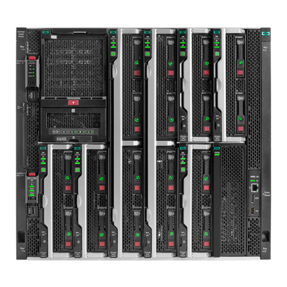
Frame front components and device bays Frame front components and device bays Item Description Item Description Device bays—Compute modules and storage modules. Front panel—Provides access to the HPE Synergy Console, through KVM or laptop. Appliance bays. Frame front components and device bays... -
Page 86: Device Bay Numbering
Device bay numbering Device bay numbering All device bays in the frame are numbered in consecutive order from lowest to highest, from left to right from top to bottom, as observed by a user looking directly at the frame. Devices larger than half-height (multi-bay devices) are numbered according to the lowest device bay number that the multi-bay device occupies. -
Page 87: Device Bay Partitions
Device bay partitions Device bay partitions Vertical frame Vertical frame partitions partitions There are two vertical partitions between device bays in the frame. These nonremovable partitions provide structural integrity to the frame as well as mechanical attach points for the horizontal shelf that divide a full-height bay into two half-height bays. Up to six full-height device modules can be installed in a frame. - Page 88 Figure 5: Optional horizontal half-shelf Figure 5: Optional horizontal half-shelf Device bay partitions...
-
Page 89: Front Panel Components
Solid green—Normal operation Flashing amber—Warning Flashing red—Critical error To resolve critical errors and warnings, connect to HPE OneView or to the HPE Synergy Console. Laptop port Provides single laptop access to the frame link module using an RJ-45 Ethernet 100BASE-TX connection. -
Page 90: Appliance Module Leds And Components
Appliance module LEDs and components Appliance module LEDs and components are the same for both an HPE Synergy Composer (1st gen) and an HPE Synergy Image Streamer. The HPE Synergy Composer2 looks slightly different but has the same LED and components on the front panel. - Page 91 Item Item Description Description Function Function Reset button Using an applicator such as a paper clip, press the recessed button to reset the appliance module. Press and release — Resets the appliance module. Press and hold until activity LED is flashing green — Initiates reimaging of the appliance module from files on the USB flash drive plugged into the appliance module.
-
Page 92: Appliance Bay Numbering
Appliance bay numbering Appliance bay numbering Appliance bay numbering... -
Page 93: Compute Module Leds And Buttons
Off = Deactivated Health status LED Solid green = Normal Flashing green (1 Hz/cycle per sec) = HPE iLO is rebooting Flashing amber = System degraded Flashing red (1 Hz/cycle per sec) = System critical Mezzanine NIC status LED... -
Page 94: System Power Led Definitions
System power LED definitions System power LED definitions The system power LED is located on the compute module Power On/Standby button. System power LED System power LED Definition Definition No power present Solid amber System is in standby Flashing green (1 Hz/cycle per sec) Performing power on sequence Solid green System on System power LED definitions... -
Page 95: Nvdimm Led Identification
NVDIMM LED identification NVDIMM LED identification Item LED description Item LED description LED color LED color Power LED Green Function LED Blue NVDIMM LED identification... -
Page 96: Nvdimm-N Led Combinations
NVDIMM-N LED combinations NVDIMM-N LED combinations State State Definition Definition NVDIMM-N Power LED (green) NVDIMM-N Power LED (green) NVDIMM-N Function LED (blue) NVDIMM-N Function LED (blue) AC power is on (12V rail) but the NVM controller is not working or not ready. AC power is on (12V rail) and the NVM controller is ready. -
Page 97: Nvdimm Function Led Patterns
NVDIMM Function LED patterns NVDIMM Function LED patterns For the purpose of this table, the NVDIMM-N LED operates as follows: Solid indicates that the LED remains in the on state. Flashing indicates that the LED is on for 2 seconds and off for 1 second. Fast-flashing indicates that the LED is on for 300 ms and off for 300 ms. -
Page 98: Storage Module Leds
Storage module LEDs Storage module LEDs The front panel and LED layout shown in the following illustration is an example. Depending on your specific model, the LEDs might be different. Item LED Item Status Status Definition Definition Drawer status Solid green Drive drawer is closed Flashing green Drive drawer is open Flashing amber Thermal warning, close the drive drawer... -
Page 99: Frame Rear Components
Frame rear components Frame rear components Item Item Description Description Fans (10) Interconnect modules (up to 6) Power supplies (6) Frame link modules (2) Frame rear components... -
Page 100: Rear Component Bay Numbering
NOTE: The arrow direction on each of the power supply icons indicates the recommended power routing to either A-side NOTE: or B-side. For more information about A-side and B-side power distribution, see the HPE Synergy Cabling Guide ( https://www.hpe.com/info/synergy-cabling-guide). https://www.hpe.com/info/synergy-cabling-guide... -
Page 101: Hpe Synergy 4-Port Frame Link Module Components And Leds
HPE Synergy 4-Port Frame Link Module components and LEDs NOTE: NOTE: HPE Synergy 4-Port Frame Link Modules require supported SFP+ DAC cables or SFP+ transceivers for cabling. For more information, see the product QuickSpecs on the Hewlett Packard Enterprise website Hewlett Packard Enterprise website . - Page 102 Flashing amber = Warning Flashing red = Critical error If the Health LED indicates a warning or a critical error, connect to HPE OneView or to the HPE Synergy Console for more information and troubleshooting assistance. HPE Synergy 4-Port Frame Link Module components and LEDs...
- Page 103 The transceiver or cable used must match the port speed of the switch used for management network connectivity. Provides a management uplink to the management network. 10GbE or 1GbE based on the cable or transceiver used. HPE Synergy 4-Port Frame Link Module components and LEDs...
-
Page 104: Hpe Synergy Frame Link Module Components And Leds
Flashing amber = Warning Flashing red = Critical error If the Health LED indicates a warning or a critical error, connect to HPE OneView or to the HPE Synergy Console for more information and troubleshooting assistance. UID button / LED Toggles the UID LED on or off. - Page 105 USB port Allows connection to the frame using a supported USB device. Devices include a keyboard or mouse for connecting to the HPE Synergy Console. To connect multiple devices, a USB hub (not included) is required. Used for performing a USB recovery frame link module firmware update.
-
Page 106: Power Supply Led
Power supply LED Power LED Power LED Condition Condition No input power to the power supply or power supply failure. Connect to the HPE Synergy console and check for power supply error messages. Solid green Normal operation Flashing amber Warning. Connect to HPE OneView Hardware Setup to troubleshoot. -
Page 107: Fan Led
Fan LED Fan LED LED color LED color Fan status Fan status Solid green Normal operation Flashing red Critical. Connect to HPE OneView Hardware Setup to troubleshoot. Fan LED... -
Page 108: Hpe Synergy 10Gb Interconnect Link Module Leds And Buttons
HPE Synergy 10Gb Interconnect Link Module LEDs and buttons HPE Synergy 10Gb Interconnect Link Module LEDs and buttons Item Item Description Description Status Status Health LED Solid green = Normal Solid amber = No power present Flashing amber = Module degraded Solid red = Installation alignment error. -
Page 109: Hpe Synergy 10Gb Interconnect Module Interconnect Link Port
HPE Synergy 10Gb Interconnect Module interconnect link port HPE Synergy 10Gb Interconnect Module interconnect link port Use an interconnect link cable when linking port L1 to a master interconnect module. HPE Synergy 10Gb Interconnect Module interconnect link port... -
Page 110: Hpe Synergy 20Gb Interconnect Link Module Leds And Buttons
HPE Synergy 20Gb Interconnect Link Module LEDs and buttons HPE Synergy 20Gb Interconnect Link Module LEDs and buttons Item Item Description Description Status Status Health LED Solid green = Normal Solid amber = No power present Flashing amber = Module degraded Solid red = Installation alignment error. -
Page 111: Hpe Synergy 20Gb Interconnect Link Module Interconnect Link Ports
HPE Synergy 20Gb Interconnect Link Module interconnect link ports HPE Synergy 20Gb Interconnect Link Module interconnect link ports Use an interconnect link cable when linking ports L1 or L2 to a master interconnect module. HPE Synergy 20Gb Interconnect Link Module interconnect link ports... -
Page 112: Hpe Synergy 50Gb Interconnect Link Module Leds And Buttons
Link Module to HPE Virtual Connect SE 100Gb F32 Module. Solid red = An error condition exists Off = Port not connected from the HPE Synergy 50Gb Interconnect Link Module to HPE Virtual Connect SE 100Gb F32 Module HPE Synergy 50Gb Interconnect Link Module LEDs and buttons... -
Page 113: Hpe Synergy 50Gb Interconnect Link Module Interconnect Link Ports
HPE Synergy 50Gb Interconnect Link Module interconnect link ports HPE Synergy 50Gb Interconnect Link Module interconnect link ports Use an interconnect link cable when linking ports L1 or L2 to a master interconnect module. NOTE: NOTE: If you are running 25 Gb speeds, you only need one cable. If you are running 50 Gb speeds, you must connect two cables. -
Page 114: Hpe Virtual Connect Se 100Gb F32 Module For Hpe Synergy Leds And Buttons
HPE Virtual Connect SE 100Gb F32 Module for HPE Synergy LEDs and buttons HPE Virtual Connect SE 100Gb F32 Module for HPE Synergy LEDs and buttons Item Item Description Description Status Status Interconnect link port LEDs Solid green = Linked Solid red = Error detected . - Page 115 Solid orange = Not logged into Attached Switch. Off = The port is not configured as an FC port. To switch between the LED modes, press the Mode button. HPE Virtual Connect SE 100Gb F32 Module for HPE Synergy LEDs and buttons...
- Page 116 The LED mode state determines which of the four Mode LEDs is lit. UID LED Solid blue = Activated Flashing blue = Firmware upgrade in progress Off = Deactivated HPE Virtual Connect SE 100Gb F32 Module for HPE Synergy LEDs and buttons...
- Page 117 See HPE OneView (http://www.hpe.com/info/oneview/docs http://www.hpe.com/info/oneview/docs) When illuminated, the QSFP28 port LEDs indicate the port operating states for each of the uplink ports in the selected mode. HPE Virtual Connect SE 100Gb F32 Module for HPE Synergy LEDs and buttons...
-
Page 118: Hpe Virtual Connect Se 100Gb F32 Module For Hpe Synergy Components
HPE Virtual Connect SE 100Gb F32 Module for HPE Synergy components HPE Virtual Connect SE 100Gb F32 Module for HPE Synergy components Item Item Component Component Description Description Interconnect link ports L1– For linking Interconnect Link modules QSFP28 uplink ports Q1–... -
Page 119: Hpe Virtual Connect Se 40Gb F8 Module For Hpe Synergy Leds And Buttons
HPE Virtual Connect SE 40Gb F8 Module for HPE Synergy LEDs and buttons HPE Virtual Connect SE 40Gb F8 Module for HPE Synergy LEDs and buttons Item Item Description Description Status Status Interconnect link port LEDs Solid green = Linked Solid red = Error detected . - Page 120 Remove and then reinstall the module. When illuminated, QSFP+ port LEDs indicate the port operating states for each of the uplink ports in the selected mode. HPE Virtual Connect SE 40Gb F8 Module for HPE Synergy LEDs and buttons...
-
Page 121: Hpe Virtual Connect Se 40Gb F8 Module For Hpe Synergy Components
HPE Virtual Connect SE 40Gb F8 Module for HPE Synergy components HPE Virtual Connect SE 40Gb F8 Module for HPE Synergy components Item Item Component Component Description Description Interconnect link ports L1– For linking satellite modules QSFP+ uplink ports Q1– Q6 40Gb Ethernet or 8Gb Fibre Channel QSFP+ uplink ports Q7–... -
Page 122: Hpe Synergy 40Gb F8 Switch Module Leds And Buttons
HPE Synergy 40Gb F8 Switch Module LEDs and buttons HPE Synergy 40Gb F8 Switch Module LEDs and buttons Item Item Description Description Status Status Interconnect link port LEDs Solid green = Linked Solid red = Error detected . Off = No link... - Page 123 Solid green = FC mode is selected. See OneView (http://www.hpe.com/info/oneview/docs http://www.hpe.com/info/oneview/docs) Remove and then reinstall the module. When illuminated, QSFP+ port LEDs indicate the port operating states for each of the uplink ports in the selected mode. HPE Synergy 40Gb F8 Switch Module LEDs and buttons...
-
Page 124: Hpe Synergy 40Gb F8 Switch Module Components
HPE Synergy 40Gb F8 Switch Module components HPE Synergy 40Gb F8 Switch Module components Item Item Component Component Description Description Interconnect link ports L1– For linking satellite modules QSFP+ uplink ports Q1– Q6 40Gb Ethernet or 8Gb Fibre Channel QSFP+ uplink ports Q7– Q8 40Gb Ethernet... -
Page 125: Mellanox Sh2200 Switch Module For Hpe Synergy Leds And Components
Mellanox SH2200 Switch Module for HPE Synergy LEDs and components Mellanox SH2200 Switch Module for HPE Synergy LEDs and components Item Item Description Description Serial port Serial port QSFP+ uplink ports (8) QSFP+ uplink ports (8) UID LED UID LED Solid blue = Activated Flashing blue = Firmware upgrade in progress. -
Page 126: Hpe Synergy Cabling
HPE Synergy Console cabling Direct connections to the HPE Synergy Console are possible by connecting a laptop directly to a frame through the front panel or by connecting KVM to the frame link module. -
Page 127: Hpe Synergy Documentation Resources
HPE Synergy documentation resources HPE Synergy documentation resources The Hewlett Packard Enterprise Support Center provides a comprehensive, one stop location for all HPE Synergy documentation, including installation instructions, maintenance and service guides, best practices, and links to additional resources. It supports filtering to improve findability. -
Page 128: Hpe Synergy Firmware Update Resources
The HPE Synergy Software Release Information site ( https://www.hpe.com/info/synergy-sw-release-information https://www.hpe.com/info/synergy-sw-release-information) provides an interactive resource for firmware update information. HPE Synergy firmware update resources are also available within HPE OneView. Figure 6: HPE Synergy Software Release Information Figure 6: HPE Synergy Software Release Information... - Page 129 HPE Synergy Software Release HPE Synergy Software Release Provides: Provides: Information web page Information web page HPE Synergy Resources A list of key HPE Synergy resources. Documentation Quick Links HPE Synergy solution documentation. HPE Synergy firmware update resources...
-
Page 130: Hpe Synergy Documentation Map
HPE Synergy documentation map HPE Synergy documentation map The Hewlett Packard Enterprise Support Center provides access to the HPE Synergy documentation. For quick links to different HPE Synergy document types, see HPE Synergy Documentation Quick Links HPE Synergy Documentation Quick Links . -
Page 131: Specifications
Specifications Specifications Specifications... -
Page 132: Hpe Synergy Quickspecs
HPE Synergy QuickSpecs HPE Synergy QuickSpecs HPE Synergy has system specifications as well as individual product and component specifications. For complete specification information, see the HPE Synergy and individual HPE Synergy product QuickSpecs on the Hewlett Packard Enterprise website (www.hpe.com/info/qs www.hpe.com/info/qs). -
Page 133: Websites
Websites Websites General websites General websites Single Point of Connectivity Knowledge (SPOCK) Storage compatibility matrix https://www.hpe.com/storage/spock https://www.hpe.com/storage/spock Storage white papers and analyst reports https://www.hpe.com/storage/whitepapers https://www.hpe.com/storage/whitepapers For additional websites, see Support and other resources. Websites... -
Page 134: Support And Other Resources
Support and other resources Support and other resources Support and other resources... -
Page 135: Accessing Hewlett Packard Enterprise Support
Accessing Hewlett Packard Enterprise Support Accessing Hewlett Packard Enterprise Support For live assistance, go to the Contact Hewlett Packard Enterprise Worldwide website: https://www.hpe.com/info/assistance https://www.hpe.com/info/assistance To access documentation and support services, go to the Hewlett Packard Enterprise Support Center website: https://www.hpe.com/support/hpesc https://www.hpe.com/support/hpesc... -
Page 136: Accessing Updates
Enterprise Support Center More Information on Access to Support Materials page: https://www.hpe.com/support/AccessToSupportMaterials https://www.hpe.com/support/AccessToSupportMaterials IMPORTANT: IMPORTANT: Access to some updates might require product entitlement when accessed through the Hewlett Packard Enterprise Support Center. You must have an HPE Passport set up with relevant entitlements. Accessing updates... -
Page 137: Remote Support
Hewlett Packard Enterprise strongly recommends that you register your device for remote support. If your product includes additional remote support details, use search to locate that information. HPE Get Connected https://www.hpe.com/services/getconnected https://www.hpe.com/services/getconnected HPE Pointnext Tech Care https://www.hpe.com/services/techcare https://www.hpe.com/services/techcare HPE Complete Care https://www.hpe.com/services/completecare https://www.hpe.com/services/completecare... -
Page 138: Customer Self Repair
Customer self repair Customer self repair Hewlett Packard Enterprise customer self repair (CSR) programs allow you to repair your product. If a CSR part needs to be replaced, it will be shipped directly to you so that you can install it at your convenience. Some parts do not qualify for CSR. Your Hewlett Packard Enterprise authorized service provider will determine whether a repair can be accomplished by CSR. -
Page 139: Warranty Information
Warranty information Warranty information To view the warranty information for your product, see the links provided below: HPE ProLiant and IA-32 Servers and Options https://www.hpe.com/support/ProLiantServers-Warranties https://www.hpe.com/support/ProLiantServers-Warranties HPE Enterprise and Cloudline Servers https://www.hpe.com/support/EnterpriseServers-Warranties https://www.hpe.com/support/EnterpriseServers-Warranties HPE Storage Products https://www.hpe.com/support/Storage-Warranties https://www.hpe.com/support/Storage-Warranties HPE Networking Products https://www.hpe.com/support/Networking-Warranties... -
Page 140: Regulatory Information
Regulatory information To view the regulatory information for your product, view the Safety and Compliance Information for Server, Storage, Power, Networking, and Rack Products, available at the Hewlett Packard Enterprise Support Center: https://www.hpe.com/support/Safety-Compliance-EnterpriseProducts https://www.hpe.com/support/Safety-Compliance-EnterpriseProducts Additional regulatory information Additional regulatory information Hewlett Packard Enterprise is committed to providing our customers with information about the chemical substances in our products as needed to comply with legal requirements such as REACH (Regulation EC No 1907/2006 of the European Parliament and the Council). -
Page 141: Documentation Feedback
Feedback button and icons (located at the bottom of an opened document) on the Hewlett Packard Enterprise Support Center portal (https://www.hpe.com/support/hpesc https://www.hpe.com/support/hpesc) to send any errors, suggestions, or comments. All document information is captured by the process. Documentation feedback...
Need help?
Do you have a question about the Synergy 12000 Frame and is the answer not in the manual?
Questions and answers