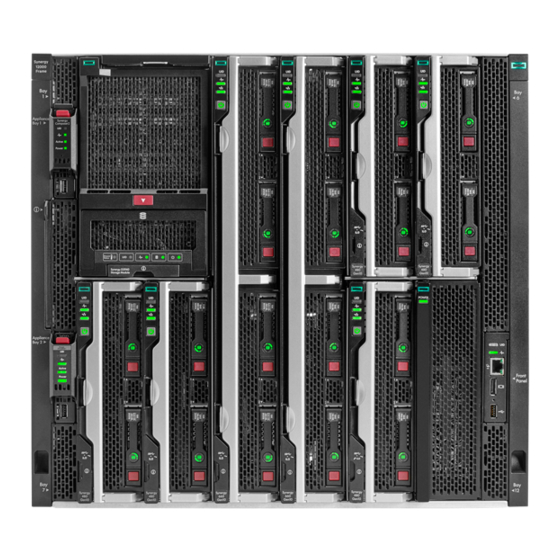
HPE Synergy 12000 Frame Installation Instructions
-48v dc power cable grounding kit
Hide thumbs
Also See for Synergy 12000 Frame:
- Setup and installation manual (101 pages) ,
- Setup and installation manual (121 pages) ,
- Maintenance and service manual (141 pages)
Advertisement
Quick Links
HPE Synergy 12000 Frame
-48V DC Power Cable
Grounding Kit
Installation Instructions
©
2017 Hewlett Packard Enterprise Development LP
Part Number: 876873-001
Published: August 2017
*876873-001*
Edition: 1
Overview
This document provides instructions for installing an HPE
Synergy 12000 Frame DC power grounding kit on an HPE
Synergy 12000 frame with and without the bracket.
For more information about frame components and
procedures, see the HPE Synergy 12000 Frame Setup and
Installation Guide on the Hewlett Packard Enterprise website
(http://www.hpe.com/info/synergy-docs).
Kit contents
•
Bracket
•
Washers (2)
•
Hex thread-forming screws (2)
•
Grounding cable (1)
•
Nuts (2)
•
This document
Warnings and cautions
WARNING:
To reduce the risk of personal injury from hot surfaces,
allow the power supply and the power supply blank to
cool before touching them.
WARNING:
To reduce the risk of electric shock or damage to the
equipment, do not connect the power cord to the power
supply until the power supply is installed.
WARNING:
To reduce the risk of electric shock or damage to the
equipment, install the HPE Synergy -48V DC power
supply in accordance with the following guidelines:
•
Install this product only in a restricted access
location.
•
Connect this product to a DC power source that can
be classified as a secondary circuit in accordance
with applicable national requirements for
information technology equipment. Generally, these
requirements are based on the International
Standard for Safety of for Information Technology
Equipment, IEC 60950-1. The source must have
one pole (Neutral/Return) referenced to earth
ground in accordance with local and regional
electric codes and regulations.
•
Connect this product to a power distribution device
that provides a means to disconnect power from the
branch supply circuit. The power distribution device
must be provided with an over-current protective
device that can interrupt fault currents available
from the main source and that is rated at no more
than 80 Amps.
WARNING:
To reduce the risk of electric shock, be sure the cable
grounding kit is properly installed and connected to a
suitable protective earth terminal before connecting the
power source to the frame.
WARNING:
•
Use ground conductors that are stranded copper
and conductors with green or green and yellow
insulation.
•
Connect any conductor that is #6 AWG or larger,
using a listed two-hole compression type connector
per GR-1089, R9-25, and TR-295.
CAUTION:
To prevent improper cooling and thermal damage, do
not operate the compute module unless all bays are
populated with either a component or a blank.
CAUTION:
Gigabit Ethernet ports (intrabuilding ports) of the
system require the use of shielded Cat5e cables
grounded at both ends. The intrabuilding ports of the
equipment are suitable for connection only to
intrabuilding, unexposed wiring, or cabling.
Do not connect the intrabuilding ports of the equipment
metallically to interfaces that connect to the outside
plant or its wiring. These intrabuilding ports are
designed for use as intrabuilding interfaces only and
require isolation from the exposed outside plant
cabling. The addition of primary protectors is not
sufficient protection to connect these interfaces
metallically to outside plant wiring.
CAUTION:
The intra-building ports of the equipment are suitable
for connection to intra-building or unexposed wiring or
cabling only. The intra-building ports of the equipment
must not be metallically connected to interfaces that
connect to the OSP or its wiring. These interfaces are
designed for use as intra-building interfaces only (Type
2 or Type 4 ports, as described in GR-1089-CORE,
Issue 4) and requires isolation from the exposed OSP
cabling. The addition of primary protectors is not
sufficient protection to connect these interfaces
metallically to OSP wiring.
NOTE:
The power input terminals are considered to be DC-I.
NOTE:
Mating surfaces must be cleaned to a bright metal
finish and an antioxidant applied before connections
are made.
NOTE:
Connections to this device must be made with shielded
cables with metallic RFI/EMI connector hoods to
maintain compliance with FCC Rules and Regulations.
NOTE:
The -48VDC-powered Synergy frame is intended to be
installed in a CBN or Common Bonding Network.
NOTE:
The Carrier-Grade HPE Synergy frame is intended for
installation into a central office or similar
telecommunications environment.
Installing the DC power grounding kit
(with bracket)
Prerequisites
The following tools are required to complete this procedure:
•
T-15 Torx screwdriver
•
8 mm socket wrench
About this task
For clarity, the rack is not shown in the images of this
procedure.
Advertisement

Related Manuals for HPE Synergy 12000 Frame


Summary of Contents for HPE Synergy 12000 Frame
- Page 1 This document provides instructions for installing an HPE that provides a means to disconnect power from the sufficient protection to connect these interfaces Synergy 12000 Frame DC power grounding kit on an HPE branch supply circuit. The power distribution device metallically to OSP wiring.
- Page 2 Installing the DC power grounding kit comments to Documentation Feedback 1. Using the 2 hex thread-forming screws, install the bracket (no bracket) (docsfeedback@hpe.com). When submitting your on the frame. feedback, include the document title, part number, edition, Tighten the screws to 15lb-in of torque.
Need help?
Do you have a question about the Synergy 12000 Frame and is the answer not in the manual?
Questions and answers