Table of Contents
Advertisement
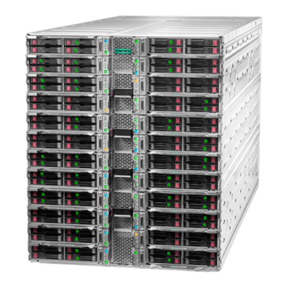
HPE Apollo k6000 Chassis
User Guide
Abstract
This document contains setup, installation, and configuration information for the HPE Apollo
Chassis. This document is for the person who installs, administers, and troubleshoots the system.
Hewlett Packard Enterprise assumes that you are qualified in the servicing of computer equipment
and trained in using safe practices when dealing with hazardous energy levels.
Part Number: 876299-003
Published: March 2018
Edition: 3
Advertisement
Table of Contents

Subscribe to Our Youtube Channel
Related Manuals for HPE Apollo k6000


Summary of Contents for HPE Apollo k6000
- Page 1 User Guide Abstract This document contains setup, installation, and configuration information for the HPE Apollo Chassis. This document is for the person who installs, administers, and troubleshoots the system. Hewlett Packard Enterprise assumes that you are qualified in the servicing of computer equipment and trained in using safe practices when dealing with hazardous energy levels.
- Page 2 © Copyright 2017, 2018 Hewlett Packard Enterprise Development LP Notices The information contained herein is subject to change without notice. The only warranties for Hewlett Packard Enterprise products and services are set forth in the express warranty statements accompanying such products and services.
-
Page 3: Table Of Contents
I/O module bay numbering..................... 13 Switch bay numbering......................14 Chassis controller or HPE Apollo Platform Manager components......... 18 Chassis controller or HPE Apollo Platform Manager LEDs and buttons........ 18 Power supply LED........................19 Installing the chassis ................20 Installation overview.......................... 20 Unpacking the system........................ - Page 4 Cabling the chassis........................... 41 Configuring the system................45 Power capping...........................45 Power capping modes......................45 Configuring a power cap........................46 Setting the chassis power cap mode with HPE APM............. 46 Troubleshooting..................47 Troubleshooting resources........................ 47 Electrostatic discharge................48 Preventing electrostatic discharge.....................48 Grounding methods to prevent electrostatic discharge..............48 Specifications....................
-
Page 5: Planning The Installation
For important safety, environmental, and regulatory information, see Safety and Compliance Information for Server, Storage, Power, Networking, and Rack Products, available at the Hewlett Packard Enterprise website (http://www.hpe.com/support/Safety-Compliance-EnterpriseProducts). Configuration guidelines Operate the chassis only when a device or blank is installed in all device bays. Before powering up the chassis, be sure to do the following: •... -
Page 6: Hpe Apollo Platform Manager
Manager allows you to manage and regulate power at a rack level by connecting the chassis that contains chassis controllers. To configure and access APM, see the HPE Apollo Platform Manager User Guide on the Hewlett Packard Enterprise website (http://www.hpe.com/support/APM_UG_en). -
Page 7: Space And Airflow Requirements
WARNING: The chassis is very heavy. To reduce the risk of personal injury or damage to the equipment: • Observe local occupational health and safety requirements and guidelines for manual material handling. • Remove all servers from the chassis before installing or moving the chassis. •... -
Page 8: Temperature Requirements
Front and rear rack doors must be adequately ventilated to allow ambient room air to enter the cabinet, and the rear door must be adequately ventilated to allow the warm air to escape from the cabinet. CAUTION: To prevent improper cooling and damage to the equipment, do not block the ventilation openings. -
Page 9: Identifying Components And Leds
Rear chassis components HPE Apollo 6000 dual-rotor hot-plug fan modules (12) Chassis I/O modules in module cage or rear I/O blanks Chassis power supplies Chassis controller or chassis controller with optional HPE Apollo Platform Manager Data switches High-speed fabric switches —... -
Page 10: Front Chassis Components
Not shown. Front chassis components Item Description Server bays Front chassis fan module bays Server bay numbering Front chassis components... -
Page 11: Front Chassis Fan Module Numbering
Rear panel components Item Description I/O module bays Rear dual-rotor fan modules Chassis controller or HPE Apollo Platform Manager Power supply bays Data switch bays High-speed fabric switch bays Front chassis fan module numbering... -
Page 12: Power Supply Numbering
Power supply numbering Rear fan module numbering Before powering up the chassis, install fan modules into all front and rear fan module bays, and install power supplies into all power supply bays. Power supply numbering... -
Page 13: Rear Fan Module Led
Rear fan module LED Status Description The fan module is working or the power is off. Solid amber The fan module has failed. I/O module bay numbering I/O modules are installed in the rear of the chassis in the bay that corresponds to its server tray. If an I/O bay is populated, an I/O-enabled server must be installed in the corresponding bay. -
Page 14: Switch Bay Numbering
Switch bay numbering Item Description Data switch bay (A) Data switch bay (B) High-speed fabric switch bay (A) High-speed fabric switch bay (B) HPE Apollo InfiniBand EDR 36-port Unmanaged Switch buttons and LEDs Switch bay numbering... - Page 15 Solid amber = Module degraded Off = No power present HPE Apollo InfiniBand EDR 36-port Unmanaged Switch components Item Description 1-12 QSFP28 ports HPE Apollo 100Gb 48-port Intel Omni-Path Architecture Unmanaged Switch buttons and LEDs HPE Apollo InfiniBand EDR 36-port Unmanaged Switch components...
- Page 16 Depress for three seconds for a soft reset. Health LED Solid green = Normal Solid amber = Module degraded Off = No power present HPE Apollo 100Gb 48-port Intel Omni-Path Architecture Unmanaged Switch components Item Description 1-24 QSFP28 ports HPE Apollo Ethernet 10GbE Pass-thru Module buttons and LEDs...
- Page 17 Solid green = Normal Solid amber = Module degraded Off = No power present Reset button Depress for three seconds for a soft reset. HPE Apollo Ethernet 10GbE Pass-thru Module components QSFP+ (4x10Gb) Port Server bay mapping Port 1 •...
-
Page 18: Chassis Controller Or Hpe Apollo Platform Manager Components
If you have a display port cable connected to each chassis controller module (up to three modules per rack) from the HPE Apollo Platform Manager, do not connect the iLO Ethernet port on the standalone chassis controller module. When using an APM in the rack, rack level iLO connectivity to the network is through the APM iLO port. -
Page 19: Power Supply Led
HPE Apollo Platform Manager reset button To reset the HPE Apollo Platform Manager, press the button. If you press and hold the button for five seconds or longer, the APM enters recovery mode. For more information, see the HPE Apollo Platform Manager User Guide on the Hewlett Packard Enterprise website (http://www.hpe.com/support/... -
Page 20: Installing The Chassis
Determining the chassis rack spacing The HPE 1.2 m standard rack supports installation of up to three chassis. For more information on installing the chassis into the rack, see the HPE Apollo k6000 Chassis Rail Kit for HPE and Third Party Racks Installation Instructions. - Page 21 WARNING: If you are going to use a lift, be sure to use a lift that can handle the load of the component. Procedure 1. Install the rails onto the rack paying attention to the labeling on the rails (Front Left and Front Right). 2.
- Page 22 4. Secure the front brackets to the rack. a. Secure the top two screws to the cage nuts (A) installed in the previous step. b. Secure the bottom two screws to the threaded holes of the rail. 5. Install the cage nuts for the rear brace. Installing the chassis...
- Page 23 6. Secure the rear brace to the rack. Installing the chassis...
-
Page 24: Installing The Chassis In The Rack
Installing the chassis in the rack WARNING: The chassis is heavy. To reduce the risk of personal injury or damage to the equipment: • Observe local occupational health and safety requirements and guidelines for manual material handling. • Use a hydraulic lift to remove the chassisfrom the rack. •... - Page 25 Manager is at the top of the chassis to ensure proper orientation in the rack. Prerequisites Install the HPE Apollo k6000 Chassis Rail Kit into the rack (Installing the rack rails on page 20). Procedure 1. Install the chassis into the rack.
- Page 26 3. Tighten the thumbscrew at the rear of the chassis. Installing the chassis...
-
Page 27: Installing The Shipping Bracket
Installing the shipping bracket IMPORTANT: Before you prepare the populated rack for shipping, you must install shipping brackets. You will need to install a shipping bracket on each side of each chassis to secure all the servers. Procedure 1. Eject the servers but do not remove them from the chassis. 2. -
Page 28: Installing The System Components
For component-specific replacement information, see the HPE Apollo k6000 Chassis Maintenance and Service Guide or the server-specific maintenance and service guides on the Hewlett Packard Enterprise website (http://www.hpe.com/info/Apollok6000-docs). -
Page 29: Installing The Rear Chassis Fan Modules
Installing the rear chassis fan modules To ensure proper airflow, install fan modules into all fan module bays before powering up the chassis. IMPORTANT: The left and right sides of the chassis are oriented 180° from each other. Components that are installed on one side of the chassis must be turned 180° when they are installed on the opposite side. -
Page 30: Installing The Chassis Controller Or Hpe Apollo Platform Manager
Procedure Install the power supply. Installing the chassis controller or HPE Apollo Platform Manager The chassis controller or APM must be installed in the chassis and working for the switch modules to power on from a cold boot for the first time. If the chassis controller is not installed, the switches will not power on. -
Page 31: Installing An I/O Module
Installing an I/O module CAUTION: To prevent electrical damage, always power down the server associated with the I/O module before installing the I/O module. CAUTION: Remove the server from the chassis before installing the I/O module. Failure to do so can result in damage to both components. -
Page 32: Installing Data Switch Options
5. If not installed, install the dual-rotor fan module (Installing the rear chassis fan modules on page 29). Installing data switch options The chassis supports installation of the following data switches: • 10GbE Integrated Switch • HPE Apollo Ethernet 10GbE Pass-Thru Module Installing data switch options... - Page 33 Install the data switch in bay 1 for the default configuration. If redundancy or a higher bandwidth is required, install a second data switch in bay 2. Population guidelines (HPE Apollo Ethernet 10GbE Pass-Thru Module) Install the pass-thru module in bay 1 for the default configuration. If redundancy or a higher bandwidth is required, install a second pass-thru module in bay 2.
- Page 34 QSFP+ Port LED-to-Server bay mapping Port 5 LED 17–Server bay 21 LED 18–Server bay 9 LED 19–Server bay 22 LED 20–Server bay 10 Port 6 LED 21–Server bay 23 LED 22–Server bay 11 LED 23–Server bay 24 LED 24–Server bay 12 When the pass-thru module is installed in bay 2, the ports and LEDs map to specific server bays as shown in the following table.
- Page 35 IMPORTANT: The chassis controller or HPE Apollo Platform Manager must be installed for a switch to power on for the first time. Once the switch is powered on by the chassis controller or HPE Apollo Platform Manager, you can remove the chassis controller, if needed.
-
Page 36: Installing High-Speed Fabric Switch Options
Install the data switch, close the release lever, and then tighten the captive screw. Installing high-speed fabric switch options The chassis supports installation of the following high-speed fabric switches: • HPE Apollo InfiniBand EDR 36-port Unmanaged Switch • HPE Apollo 100 Gb 48-port Intel Omni-Path Architecture Unmanaged Switch Installing high-speed fabric switch options... - Page 37 Use the following table to determine bay population requirements. Server configuration Switch bay population 1 OPA mezzanine card installed in slot 1*, Bay 3 = HPE Apollo 100 Gb 48-port Intel Omni-Path connected by a single mezzanine cable Architecture Unmanaged Switch 2 OPA mezzanine cards, connected by a...
- Page 38 IMPORTANT: The chassis controller or HPE Apollo Platform Manager must be installed for a switch to power on for the first time. Once the switch is powered on by the chassis controller or HPE Apollo Platform Manager, you can remove the chassis controller, if needed.
- Page 39 a. Make sure that the orientation of the release lever is correct for installation in bay 3. b. Prepare the switch for installation. Make sure that the release lever is fully open. c. Install the switch, close the release lever, and then tighten the captive screw. CAUTION: The switch will slide smoothly into the slot and connect to the backplane.
- Page 40 CAUTION: The switch will slide smoothly into the slot and connect to the backplane. Forcing the switch into the slot or into the connector will damage components. Installing the chassis...
-
Page 41: Cabling
For configurations that include the HPE Apollo Platform Manager, the following additional cables are required: • One HPE Apollo Platform Manager USB to MicroDB9 Cable to the PDM ports on each HPE Apollo Platform Manager. • One consolidated management cable per chassis to the APM input ports on each chassis controller or HPE Apollo Platform Manager. - Page 42 HPE Apollo Platform Manager to consolidated management ports on the chassis controllers (orange) ◦ HPE Apollo Platform Manager to network (pink) ◦ iLO connection to network (blue) ◦ HPE Apollo Platform Manager serial cable (used for initial APM setup) (869324-001) (green) Cabling...
- Page 43 • Chassis with standard chassis controllers ◦ Chassis controllers to network (pink) 2. Connect the chassis power supply cables (blue) to a PDU. CAUTION: The following illustration assumes that you are using one PDU per chassis that has a minimum capacity of 17.28 kVA and a dedicated circuit breaker for each power supply in the chassis. Connecting two or more power supplies to a single breaker will cause the breaker to trip.
- Page 44 3. Apply power to the chassis. Cabling...
-
Page 45: Configuring The System
A global power cap can also be applied to all enclosures with one APM command. For more information on using the APM, see the HPE Apollo Platform Manager User Guide on the Hewlett Packard Enterprise website (http://www.hpe.com/support/ APM_UG_en). -
Page 46: Configuring A Power Cap
Configuring a power cap To configure power capping, you can use the HPE Apollo Platform Manager, a rack level device that can control power caps for all enclosures in the rack. For more information, see the HPE Apollo Platform Manager User Guide (http://www.hpe.com/support/APM_UG_en) on the Hewlett Packard Enterprise website. -
Page 47: Troubleshooting
• Error Message Guide for HPE ProLiant Gen10 servers and HPE Synergy provides a list of error messages and information to assist with interpreting and resolving error messages. •... -
Page 48: Electrostatic Discharge
Electrostatic discharge Preventing electrostatic discharge To prevent damaging the system, be aware of the precautions you must follow when setting up the system or handling parts. A discharge of static electricity from a finger or other conductor may damage system boards or other static-sensitive devices. -
Page 49: Specifications
301.64 kg (665.00 lb) Weight, empty 66.68 kg (147.00 lb) Power specifications The power requirements for the HPE Apollo k6000 Chassis are met by the following components: • HPE 2650W Hot Plug Titanium Plus Power Supply • HPE 2650W 277VAC Hot Plug Power Supply •... -
Page 50: Dc Power
Nom (V) +12.25 Maximum (V) +12.593 % Reg +2.8%/-2.8% Single-phase power HPE 2650W Hot Plug Titanium Plus Power Supply Specification HPE 2650W Hot Plug Titanium Plus Power Supply Power cord IEC-320 C19-C20 2 m (6.5 ft) Output 2650 W per power supply... -
Page 51: Hot-Plug Power Supply Calculations
Rated input power per power supply 3620 VA (maximum) Hot-plug power supply calculations For hot-plug power supply specifications and calculators to determine electrical and heat loading for the server, see the Hewlett Packard Enterprise Power Advisor website (http://www.hpe.com/info/poweradvisor/ online). Hot-plug power supply calculations... -
Page 52: Websites
Websites General websites Hewlett Packard Enterprise Information Library www.hpe.com/info/EIL Single Point of Connectivity Knowledge (SPOCK) Storage compatibility matrix www.hpe.com/storage/spock Storage white papers and analyst reports www.hpe.com/storage/whitepapers For additional websites, see Support and other resources. Websites... -
Page 53: Support And Other Resources
Support and other resources Accessing Hewlett Packard Enterprise Support • For live assistance, go to the Contact Hewlett Packard Enterprise Worldwide website: http://www.hpe.com/assistance • To access documentation and support services, go to the Hewlett Packard Enterprise Support Center website: http://www.hpe.com/support/hpesc Information to collect •... -
Page 54: Customer Self Repair
IMPORTANT: Access to some updates might require product entitlement when accessed through the Hewlett Packard Enterprise Support Center. You must have an HPE Passport set up with relevant entitlements. Customer self repair Hewlett Packard Enterprise customer self repair (CSR) programs allow you to repair your product. If a CSR part needs to be replaced, it will be shipped directly to you so that you can install it at your convenience. -
Page 55: Regulatory Information
Documentation Feedback (docsfeedback@hpe.com). When submitting your feedback, include the document title, part number, edition, and publication date located on the front cover of the document. For online help content, include the product name, product version, help edition, and publication date located on the legal notices page.
Need help?
Do you have a question about the Apollo k6000 and is the answer not in the manual?
Questions and answers