Table of Contents
Advertisement
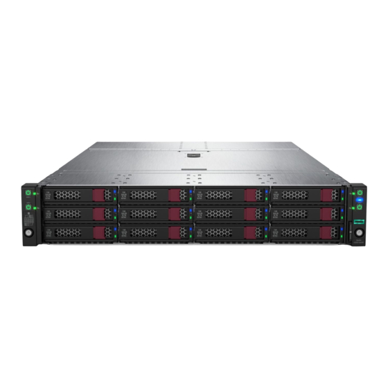
HPE Apollo 2000 Gen10 Chassis User
Guide
Abstract
This document contains setup, installation, and configuration information for the HPE Apollo
2000 Chassis. This document is for the person who installs, administers, and troubleshoots
the system. Hewlett Packard Enterprise assumes that you are qualified in the servicing of
computer equipment and trained in using safe practices when dealing with hazardous energy
levels.
Part Number: 879112-003
Published: June 2018
Edition: 3
Advertisement
Table of Contents

Related Manuals for HPE Apollo 2000 Gen10


Summary of Contents for HPE Apollo 2000 Gen10
- Page 1 Guide Abstract This document contains setup, installation, and configuration information for the HPE Apollo 2000 Chassis. This document is for the person who installs, administers, and troubleshoots the system. Hewlett Packard Enterprise assumes that you are qualified in the servicing of computer equipment and trained in using safe practices when dealing with hazardous energy levels.
- Page 2 © Copyright 2017, 2018 Hewlett Packard Enterprise Development LP Notices The information contained herein is subject to change without notice. The only warranties for Hewlett Packard Enterprise products and services are set forth in the express warranty statements accompanying such products and services. Nothing herein should be construed as constituting an additional warranty. Hewlett Packard Enterprise shall not be liable for technical or editorial errors or omissions contained herein.
-
Page 3: Table Of Contents
Contents HPE Apollo 2000 Gen10 System............6 Introduction........................... 6 Planning the installation.................7 Safety and regulatory compliance....................7 Product QuickSpecs........................7 Configuration guidelines....................... 7 Determining power and cooling configurations................7 Power requirements......................7 HPE Apollo Platform Manager................... 7 Hot-plug power supply calculations..................8 Compiling the documentation....................... 8 Warnings and cautions........................8... - Page 4 HPE 800W Flex Slot Universal Hot-plug Low Halogen Power Supply......77 HPE 800W Flex Slot -48VDC Hot-plug Low Halogen Power Supply....... 77 HPE 1600W Flex Slot Platinum Hot Plug Low Halogen Power Supply......78 HPE 2200W Flex Slot Platinum Hot Plug Low Halogen Power Supply......79 Hot-plug power supply calculations....................
- Page 5 Accessing updates........................82 Customer self repair........................83 Remote support.......................... 83 Warranty information........................83 Regulatory information........................84 Documentation feedback......................84 Acronyms and abbreviations...............85 Contents...
-
Page 6: Hpe Apollo 2000 Gen10 System
HPE Apollo 2000 Gen10 System Introduction The HPE Apollo 2000 Gen10 System consists of a chassis and servers. There are four chassis options with different storage configurations. To ensure proper thermal cooling, all server tray slots on the chassis must be populated with servers or server tray blanks. -
Page 7: Planning The Installation
HPE Apollo Platform Manager, formerly named HPE Advanced Power Manager, is a point of contact for system administration. To install, configure, and access HPE APM, see the HPE Apollo Platform Manager User Guide on the Hewlett Packard Enterprise website (http://www.hpe.com/support/APM_UG_en). -
Page 8: Hot-Plug Power Supply Calculations
For more information on the hot-plug power supply and calculators to determine server power consumption in various system configurations, see the Hewlett Packard Enterprise Power Advisor website (http://www.hpe.com/info/poweradvisor/online). Compiling the documentation The documentation, while delivered individually and in various formats, works as a system. Consult these documents before attempting installation. -
Page 9: Space And Airflow Requirements
WARNING: To reduce the risk of electric shock or damage to the equipment: • Never reach inside the chassis while the system is powered up. • Perform service on system components only as instructed in the user documentation. CAUTION: Always be sure that equipment is properly grounded and that you follow proper grounding procedures before beginning any installation procedure. -
Page 10: Temperature Requirements
CAUTION: If a third-party rack is used, observe the following additional requirements to ensure adequate airflow and to prevent damage to the equipment: • Front and rear doors—If the 42U rack includes closing front and rear doors, you must allow 5,350 sq cm (830 sq in) of holes evenly distributed from top to bottom to permit adequate airflow (equivalent to the required 64 percent open area for ventilation). - Page 11 WARNING: Remove power from the power supply before performing any installation steps or maintenance on the power supply. CAUTION: The server equipment connects the earthed conductor of the DC supply circuit to the earthing conductor at the equipment. For more information, see the documentation that ships with the power supply.
-
Page 12: Identifying Components And Leds
Identifying components and LEDs System components Item Description RCM module (optional) Power supply HPE Apollo 2000 Gen10 Chassis HPE ProLiant XL190r Gen10 Server HPE ProLiant XL170r Gen10 Server Server tray blank Front panel components HPE Apollo r2200 Gen10 Chassis Identifying components and LEDs... - Page 13 Chassis serial label pull tab HPE Apollo r2600 Gen10 Chassis Item Description Left bezel ear SFF hot-plug drives Right bezel ear Chassis serial label pull tab Non-removable bezel blank HPE Apollo r2800 Gen10 Chassis with 16 NVMe Identifying components and LEDs...
-
Page 14: Front Panel Leds
Description Left bezel ear NVMe drives Right bezel ear Chassis serial label pull tab Non-removable bezel blanks HPE Apollo r2800 Gen10 Chassis (24 SFF model with storage expander backplane) Item Description Left bezel ear SFF hot-plug drives Right bezel ear... - Page 15 Item Description Status Power On/Standby button and system power Solid green = System on LED (Server 1) Flashing green = Performing power on sequence Solid amber = System in standby Off = No power present Power On/Standby button and system power Solid green = System on LED (Server 2) Flashing green = Performing power on...
-
Page 16: Power Fault Leds
Item Description Status UID button/LED Solid blue = Activated Flashing blue: • 1 flash per second = Remote management or firmware upgrade in progress • 4 flashes per second = iLO manual soft reboot sequence initiated • 8 flashes per second = iLO manual hard reboot sequence in progress Off = Deactivated Power On/Standby button and system power... -
Page 17: Rear Panel Components
Processor 2 flashes Memory 3 flashes Riser board PCIe slots 4 flashes FlexibleLOM 5 flashes Removable HPE Flexible Smart Array 6 flashes controller System board PCIe slots 7 flashes Power backplane or storage backplane 8 flashes Power supply 9 flashes... -
Page 18: Power Supply Leds
Item Description Server 3 Power supply 2 RCM module (optional) Power supply 1 Server 1 Power supply LEDs Power supply LEDs... -
Page 19: Fan Locations
Item Description Status Power supply 1 LED Solid green = Normal Off = One or more of the following conditions exists: • Power is unavailable • Power supply failed • Power supply is in standby mode • Power supply error Power supply 2 LED Solid green = Normal Off = One or more of the following conditions... - Page 20 Apollo r2200 Gen10 Chassis (1U servers in AHCI mode) Item Description Server 1 drive bays Server 2 drive bays Server 3 drive bays Server 4 drive bays Apollo r2200 Gen10 Chassis (2U servers in AHCI mode) Item Description Server 1 drive bays Server 3 drive bays Apollo r2200 Gen10 Chassis (1U and 2U servers using embedded SATA S100i or a Smart Array controller)
- Page 21 Apollo r2600 Gen10 Chassis (1U servers in AHCI mode) Item Description Supported drives Server 1 drive bays Drive bays 1, 2, 3, and 4 support SFF SmartDrives only. Drive bays 5 and 6 support both SFF SmartDrives and NVMe drives. Server 2 drive bays Drive bays 1 and 2 support both SFF SmartDrives and NVMe drives.
- Page 22 • Server 3 corresponds to drive bays 3-1 through 4-6. Apollo r2800 Gen10 Chassis with 16 NVMe IMPORTANT: The HPE Apollo r2800 Gen10 Chassis with 16 NVMe does not support servers using the embedded SATA HPE Dynamic Smart Array S100i Controller or any type-p plug-in Smart Array Controller with internal ports and cables.
- Page 23 Drive bay mapping configuration changes may be made from any server node and take effect after all server nodes in the HPE Apollo r2800 Chassis are turned off and the Chassis firmware is able to reset the storage expander backplane. All nodes must remain powered off for at least 5 seconds after executing the configuration changes.
-
Page 24: Hot-Plug Drive Led Definitions
Hot-plug drive LED definitions SmartDrive hot-plug drive LED definitions Item Description Status Locate • Solid blue = The drive is being identified by a host application. • Flashing blue = The drive carrier firmware is being updated or requires an update. Activity ring LED •... -
Page 25: Low-Profile Lff Hot-Plug Drive Led Definitions
Item Description Status Do not remove LED • Solid white = Do not remove the drive. Removing the drive causes one or more of the logical drives to fail. • Off = Removing the drive does not cause a logical drive to fail. - Page 26 Online/Activity LED (green) Fault/UID LED (amber/blue) Definition On, off, or flashing Alternating amber and blue One or more of the following conditions exist: • The drive has failed. • A predictive failure alert has been received for this drive. • The drive has been selected by a management application.
-
Page 27: Nvme Ssd Components
Online/Activity LED (green) Fault/UID LED (amber/blue) Definition 4 flashes per second Flashing amber The drive is active but a predictive failure alert has been received for this drive. Replace the drive as soon as possible. 4 flashes per second The drive is active and is operating normally. - Page 28 Item Description Status Drive status LED Solid green = The drive is a member of one or more logical drives. Flashing green = The drive is rebuilding or performing a RAID migration, stripe size migration, capacity expansion, or logical drive extension, or is erasing. Flashing amber/green = The drive is a member of one or more logical drives and predicts the drive will fail.
-
Page 29: Rcm Module Components
RCM module components Item Description iLO connector HPE APM 2.0 connector iLO connector RCM module LEDs RCM module components... - Page 30 Item Description Status Green or flashing green = Network activity iLO activity LED Off = No network activity Green = Linked to network iLO link LED Off = No network connection iLO link LED Green = Linked to network iLO link LED Off = No network connection Green or flashing green = Network activity iLO activity LED...
-
Page 31: Installing The Chassis
HPE Apollo 2000 Gen10 Chassis • Rack rail kit • System components and cabling The following documents also ship with the HPE Apollo 2000 Gen10 Chassis: • Start Here for Important Setup Information • Safety, Compliance, and Warranty Information Preparing the chassis for installation If installing the Smart Storage Battery and redundant fan options, install these options before installing the chassis into the rack. - Page 32 IMPORTANT: Label the drives before removing them. The drives must be returned to their original locations. 2. Remove the hot-plug drive. • SFF SmartDrive • Low-profile LFF hot-plug drive • NVMe hot-plug drive Installing the chassis...
- Page 33 3. Remove the server from the chassis: a. Loosen the thumbscrew. b. Pull back the handle. CAUTION: To avoid damage to the server, always support the bottom of the server when removing it from the chassis. c. Remove the server: •...
-
Page 34: Installing The Smart Storage Battery For The Regular Power Supply
Installing the Smart Storage Battery for the regular Power Supply Procedure 1. If installing a Smart Storage Battery or redundant fan option, remove the access panel. NOTE: After the Smart Storage Battery is installed, it might take up to two hours to charge. Features requiring backup power are not enabled until the battery is fully charged. - Page 35 a. Remove the battery holder. NOTE: Depending on the power supply installed, the design of the Smart Storage battery and the fan cage and module may be slightly different. b. Install the Smart Storage Battery into the holder and route the cable. c.
-
Page 36: Installing The Smart Storage Battery For The H-Watt Power Supply
3. Install the access panel. Installing the Smart Storage Battery for the H-Watt Power Supply Procedure 1. To install the Smart Storage Battery, remove the bezel, the hot-plug drives, and the server from the chassis. 2. Install the fan into the fan cage. Installing the Smart Storage Battery for the H-Watt Power Supply... - Page 37 3. Connect the fan cage cable to the power distribution board connector and install the fan cage. 4. Install the Smart Storage Battery into the holder. Route the battery cable and connect it to the power distribution board. Installing the chassis...
-
Page 38: Installing The Redundant Fan Option
5. Install the battery holder. 6. Install the redundant fan option. Installing the redundant fan option Procedure 1. To install the redundant fan option, do the following: NOTE: Depending on the power supply installed, the design of the SmartStorage battery and the fan cage and module may be slightly different. - Page 39 c. Route the fan 1 and fan 5 cables through the grooves on the top of fan 5. Then secure the cables on top of fan 5 with two strips of adhesive tape. d. Repeat the previous step for fans 6, 7, and 8. e.
-
Page 40: Installing The Chassis Into The Rack
2. Install the access panel. Installing the chassis into the rack WARNING: The chassis is very heavy. To reduce the risk of personal injury or damage to the equipment: • Observe local occupational health and safety requirements and guidelines for manual material handling. - Page 41 Be sure sufficient clearance exists for cabling, installation and removal of the chassis, and actuation of the rack doors. IMPORTANT: When installing each chassis into the rack, be sure that the HPE Apollo Platform Manager is at the top of the chassis to ensure proper orientation in the rack.
-
Page 42: Installing The 2U Rack Rail Kit
Installing the 2U rack rail kit WARNING: To reduce the risk of personal injury or damage to the equipment, be sure that: • The leveling jacks are extended to the floor. • The full weight of the rack rests on the leveling jacks. •... - Page 43 • Round-hole rack 3. Install the chassis into the rack. Installing the chassis...
- Page 44 4. Tighten the thumbscrews. 5. If the rack is being shipped, install the shipping bracket for the top chassis only. Installing the chassis...
-
Page 45: Installing Hardware Options Into The Server
Installing hardware options into the server To install hardware options into the server, see the server user guide on the Hewlett Packard Enterprise website. Installing the system components If components were removed during the chassis installation or additional components were ordered, install each device using the procedures in this section. -
Page 46: Installing The Server Tray Blank
• 2U server Installing the server tray blank CAUTION: To ensure proper thermal cooling, all server tray slots must be populated with servers or server tray blanks. Procedure Install the server tray blank. Installing the server tray blank... -
Page 47: Installing A Hot-Plug Ac Power Supply
Installing a hot-plug AC power supply Procedure 1. Access the product rear panel. 2. Remove the power supply blank. 3. Slide the power supply into the bay until it clicks into place. Installing a hot-plug AC power supply... -
Page 48: Installing A Hot-Plug Dc Power Supply
The following input power cord option might be purchased from an authorized reseller: J6X43A—HPE 12 AWG 48 V DC 3.0 m Power Cord If you are not using an input power cord option, the power supply cabling should be made in consultation with a licensed electrician and be compliant with local code. - Page 49 WARNING: To reduce the risk of electric shock, fire, and damage to the equipment, you must install this product in accordance with the following guidelines: • This power supply is intended only for installation in Hewlett Packard Enterprise servers located in a restricted access location.
- Page 50 Crimp the ring tongue to the ground cable from the -48 V DC power source. Remove the terminal block connector. Installing the chassis...
- Page 51 Loosen the screws on the terminal block connector. Attach the ground (earthed) wire to the ground screw and washer and tighten to 1.47 N m (13 lb-in) of torque. The ground wire must be connected before the -48 V wire and the return wire. The ground wire must be connected before the -48 V wire and the return wire.
- Page 52 Insert the -48 V wire into the left side of the terminal block connector, and then tighten the screw to 1.3 N m (10 lb-in) of torque. Insert the return wire into the right side of the connector, and then tighten the screw to 1.3 N m (10 lb-in) of torque.
- Page 53 10. Install the terminal block connector in the power supply. 11. To prevent accidental power cord disconnection when sliding the server in and out of the chassis, secure the power cord, wires, and/or cables in the strain relief strap attached to the power supply handle: a.
-
Page 54: Drive Options
12. Slide the power supply into the bay until it clicks into place. Drive options The different chassis options support SAS, SATA, and NVMe drives. For more information on drive support, see Drive bay numbering. IMPORTANT: Depending on the chassis configuration and the components installed in the servers, it might be necessary to limit the number of drives installed in the chassis. - Page 55 Removing the drive blank Remove the components as indicated. • SFF drive blank • Low-profile LFF drive blank Installing a hot-plug SAS or SATA drive Prerequisites Before installing this option, be sure that you have the following: The components included with the hardware option kit. Procedure 1.
- Page 56 • Low-profile LFF hot-plug drive 3. Install the drive. • SFF SmartDrive • Low-profile LFF hot-plug drive Installing the chassis...
- Page 57 4. Determine the status of the drive from the drive LED definitions (Hot-plug drive LED definitions). Installing the NVMe drives NVMe drives are supported in the HPE Apollo r2600 Gen10 Chassis and in the HPE Apollo r2800 Gen10 Chassis with 16 NVMe. For more information, see Drive bay numbering.
-
Page 58: Installing The Optional 2U Bezel
4. Install the drives. 5. Install an SFF drive blank in any unused drive bays. Installing the optional 2U bezel NOTE: Your chassis may look slightly different than shown. Procedure Install the bezel. Installing the optional 2U bezel... - Page 59 Installing the chassis...
-
Page 60: Cabling
Cabling Cabling guidelines The cable colors in the cabling diagrams used in this chapter are for illustration purposes only. Most of the server cables are black. Observe the following guidelines when working with server cables. Before connecting cables • Note the port labels on the PCA components. Not all of these components are used by all servers: ◦... -
Page 61: Cabling The Chassis
CAUTION: To prevent loss of data and damage to the PDU, each power supply must be connected to a dedicated circuit breaker. Do not connect multiple power supplies to a single circuit breaker. Front I/O cabling HPE Apollo r2200 Gen10 Chassis Cabling the chassis... -
Page 62: Drive Backplane Power Cabling
Cable color Description Orange Left front I/O cable Blue Right front I/O cable HPE Apollo r2600 Gen10 Chassis and HPE Apollo r2800 Gen10 Chassis with 16 NVMe Cable color Description Orange Left front I/O cable Blue Right front I/O cable... - Page 63 Chassis power cable for hot-plug drives Amber Chassis power cable for server 3 and server 4 Pink Chassis pass-through power supply cable HPE Apollo r2600 Gen10 Chassis Cable color Description Orange r2600/r2800 Gen10 Chassis power cable for server 1 and server 2...
-
Page 64: Fan Power Cabling
HPE Apollo r2800 Gen10 Chassis Cable color Description Orange r2600/r2800 Gen10 Chassis power cable for server 1 and server 2 Blue Chassis power cable for hot-plug drives Amber Chassis power cable for server 3 and server 4 Pink Chassis pass-through power supply cable... -
Page 65: Fan Module Cabling
Fan module cabling Smart Storage Battery cabling Fan module cabling... -
Page 66: Rcm 2.0 Cabling
RCM 2.0 cabling Connecting the chassis to the network The optional RCM module can connect multiple chassis to the same network. Installing the RCM module Prerequisites Observe the following rules and limitations when installing or replacing an RCM module: • Before installing the RCM module, ensure that all servers in the chassis are powered down. - Page 67 2. Remove the strain relief strap from the bottom power supply handle. CAUTION: Avoid tight bend radii to prevent damaging the internal wires of a power cord or a node cable. Never bend power cords and node cables tight enough to cause a crease in the sheathing.
-
Page 68: Connecting Multiple Chassis To The Network With The Rcm Module Ilo Ports
b. Release the strain relief strap on the top power supply handle. c. Secure both power cords in the strain relief strap on the top power supply handle. Connecting multiple chassis to the network with the RCM module iLO ports Procedure If using the RCM module iLO ports to connect the chassis to a network, connect all cables to the RCM module and the network. -
Page 69: Connecting The Optional Hpe Apm Module
NOTE: The arrow indicates the connection to the network. Connecting the optional HPE APM module Procedure 1. Connect the APM to the network. 2. Connect the APM to the RCM modules. Connecting power cables and applying power to the chassis Procedure 1. -
Page 70: Configuring The System
A global power cap can also be applied to all enclosures with one APM command. For more information on using the APM, see the HPE Apollo Platform Manager User Guide on the Hewlett Packard Enterprise website (http://www.hpe.com/ support/APM_UG_en). -
Page 71: Configuring A Power Cap
Configuring a power cap To configure power capping, you can use the HPE Apollo Platform Manager, a rack level device that can control power caps for all enclosures in the rack. For more information, see the HPE Apollo Platform Manager User Guide (http://www.hpe.com/support/APM_UG_en) on the Hewlett Packard Enterprise website. -
Page 72: Troubleshooting
• Simplified Chinese The HPE ProLiant Gen10 Troubleshooting Guide, Volume II: Error Messages provides a list of error messages and information to assist with interpreting and resolving error messages on ProLiant servers and server blades. To view the guide, select a language: •... -
Page 73: Electrostatic Discharge
Electrostatic discharge Preventing electrostatic discharge To prevent damaging the system, be aware of the precautions you must follow when setting up the system or handling parts. A discharge of static electricity from a finger or other conductor may damage system boards or other static-sensitive devices. This type of damage may reduce the life expectancy of the device. -
Page 74: Specifications
40°C to 45°C (104°F to 113°F) at sea level with an altitude derating of 1.0°C per every 125 m (1.8°F per every 410 ft) above 900 m (2953 ft) to a maximum of 3050 m (10,000 ft). Mechanical specifications HPE Apollo r2200 Gen10 Chassis Specifications Value Dimensions —... -
Page 75: Power Supply Specifications
Depending on installed options, the system is configured with one of the following power supplies: • HPE 800W Flex Slot Platinum Hot Plug Low Halogen Power Supply • HPE 800W Flex Slot Universal Hot Plug Low Halogen Power Supply... -
Page 76: Hpe 800W Flex Slot Platinum Hot-Plug Low Halogen Power Supply
• HPE 800W Flex Slot -48VDC Hot Plug Low Halogen Power Supply • HPE 1600W Flex Slot Platinum Hot Plug Low Halogen Power Supply • HPE 2200W Flex Slot Platinum Hot Plug Low Halogen Power Supply For more information about the power supply features, specifications, and compatibility, see the Hewlett Packard Enterprise website . -
Page 77: Hpe 800W Flex Slot Universal Hot-Plug Low Halogen Power Supply
HPE 800W Flex Slot Universal Hot-plug Low Halogen Power Supply Specification Value Input requirements — Rated input voltage 200 VAC to 277 VAC 380 VDC Rated input frequency 50 Hz to 60 Hz Rated input current 4.4 A at 200 VAC 3.1 A at 277 VAC... -
Page 78: Hpe 1600W Flex Slot Platinum Hot Plug Low Halogen Power Supply
• Switching or disconnecting devices must not be in the earthed circuit conductor between the DC source and the point of connection of the earthing electrode conductor. HPE 1600W Flex Slot Platinum Hot Plug Low Halogen Power Supply Specification Value... -
Page 79: Hpe 2200W Flex Slot Platinum Hot Plug Low Halogen Power Supply
1,600 W at 240 VDC input Maximum peak power 2,200 W for 1 ms (turbo mode) at 200 VAC to 240 VAC input HPE 2200W Flex Slot Platinum Hot Plug Low Halogen Power Supply Specification Value Input requirements Rated input voltage... -
Page 80: Hot-Plug Power Supply Calculations
1800 W at 240 VDC for China only Hot-plug power supply calculations For hot-plug power supply specifications and calculators to determine electrical and heat loading for the server, see the Hewlett Packard Enterprise Power Advisor website (http://www.hpe.com/info/ poweradvisor/online). Hot-plug power supply calculations... -
Page 81: Websites
Websites • Hewlett Packard Enterprise Information Library • Hewlett Packard Enterprise Support Center • Contact Hewlett Packard Enterprise Worldwide • Subscription Service/Support Alerts • Software Depot • Customer Self Repair • Insight Remote Support • Serviceguard Solutions for HP-UX • Single Point of Connectivity Knowledge (SPOCK) Storage compatibility matrix •... -
Page 82: Support And Other Resources
Support and other resources Accessing Hewlett Packard Enterprise Support • For live assistance, go to the Contact Hewlett Packard Enterprise Worldwide website: http://www.hpe.com/assistance • To access documentation and support services, go to the Hewlett Packard Enterprise Support Center website: http://www.hpe.com/support/hpesc Information to collect •... -
Page 83: Customer Self Repair
IMPORTANT: Access to some updates might require product entitlement when accessed through the Hewlett Packard Enterprise Support Center. You must have an HPE Passport set up with relevant entitlements. Customer self repair Hewlett Packard Enterprise customer self repair (CSR) programs allow you to repair your product. If a CSR part needs to be replaced, it will be shipped directly to you so that you can install it at your convenience. -
Page 84: Regulatory Information
Documentation Feedback (docsfeedback@hpe.com). When submitting your feedback, include the document title, part number, edition, and publication date located on the front cover of the document. For online help content, include the product name, product version, help edition, and publication date located on the legal notices page. -
Page 85: Acronyms And Abbreviations
Advanced Host Controller Interface Customer Self Repair double data rate graphics processing unit HP SUM HP Smart Update Manager HPE APM HPE Advanced Power Manager HPE SSA HPE Smart Storage Administrator International Electrotechnical Commission Integrated Lights-Out Integrated Management Log International Organization for Standardization... - Page 86 PCIe Peripheral Component Interconnect Express power distribution unit POST Power-On Self-Test RBSU ROM-Based Setup Utility Rack Consolidation Management RDIMM registered dual in-line memory module Remote Desktop Protocol RoHS Restriction of Hazardous Substances serial attached SCSI SATA serial ATA small form factor Service Pack for ProLiant serial, USB, video TMRA...
Need help?
Do you have a question about the Apollo 2000 Gen10 and is the answer not in the manual?
Questions and answers