Sign In
Upload
Download
Table of Contents
Contents
Add to my manuals
Delete from my manuals
Share
URL of this page:
HTML Link:
Bookmark this page
Add
Manual will be automatically added to "My Manuals"
Print this page
×
Bookmark added
×
Added to my manuals
Manuals
Brands
Beckhoff Manuals
Touch terminals
EL6601
Documentation
Beckhoff EL6601 Documentation
Switch terminals for ethernet
Hide thumbs
1
2
3
4
5
6
7
8
9
10
11
12
13
14
15
16
17
18
19
20
21
22
23
24
25
26
27
28
29
30
31
32
33
34
35
36
37
38
39
40
41
42
43
44
45
46
47
48
49
50
51
52
53
54
55
56
57
58
59
60
61
62
63
64
65
66
67
68
69
70
71
72
73
74
75
76
77
78
79
80
81
82
83
84
85
86
87
88
89
90
91
92
93
94
95
96
97
98
99
100
101
102
103
104
105
106
107
108
109
110
111
112
113
114
115
116
117
118
119
120
121
122
123
124
125
126
127
128
129
130
131
132
133
134
135
136
137
138
139
140
141
142
143
144
145
146
147
148
149
150
151
152
153
154
155
156
157
158
159
160
161
162
163
page
of
163
Go
/
163
Contents
Table of Contents
Bookmarks
Table of Contents
Table of Contents
1 Foreword
Notes on the Documentation
Safety Instructions
Documentation Issue Status
Version Identification of Ethercat Devices
Fig. 1 EL5021 el Terminal, Standard IP20 IO Device with Serial/ Batch Number and Revision ID (Since 2014/01)
Fig. 2 EK1100 Ethercat Coupler, Standard IP20 IO Device with Serial/ Batch Number
Fig. 3 CU2016 Switch with Serial/ Batch Number
Fig. 4 EL3202-0020 with Serial/ Batch Number 26131006 and Unique ID-Number 204418
Fig. 5 EP1258-00001 IP67 Ethercat Box with Batch Number/ Date Code 22090101 and Unique Se- Rial Number 158102
Fig. 6 EP1908-0002 IP67 Ethercat Safety Box with Batch Number/ Date Code 071201FF and Unique Serial Number 00346070
Fig. 7 EL2904 IP20 Safety Terminal with Batch Number/ Date Code 50110302 and Unique Serial Num- Ber 00331701
Fig. 8 ELM3604-0002 Terminal with Unique ID Number (QR Code) 100001051 and Serial/ Batch Num- Ber 44160201
2 Product Overview
Introduction
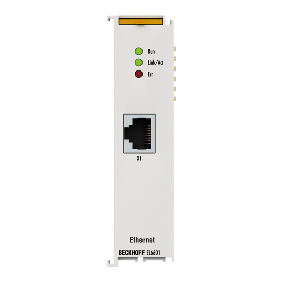
Fig. 9 EL6601, EL6614
Fig. 10 EL6601 as a Virtual, Field-Distributed Switch
Technical Data
Basic Function Principles
Fig. 11 El66Xx Data Diagram
Fig. 12 IP Settings Ethercat Port
El66Xx - Non Realtime
Fig. 13 Connection Failure between Primary Ethercat Port and 1St Slave (X)
Fig. 14 Real Frame Structure from the Twincat System Manager
Fig. 15 Default Setting of the El66Xx as Switch Port Without IP Address Assignment
Fig. 16 from FW03: Settings for Dynamically Assigned IP Address
Fig. 17 Default Mailbox Settings
Fig. 18 Increasing the Mailbox
Fig. 19 Twincat 2.11, Virtual Twincat Switch
El66Xx and Beckhoff Network Variables
Explanation Network Variables
Fig. 20 Twincat 2.11, Virtual Twincat Switch
Settings in the System Manager
Fig. 21 Notice on Exceeding Configured Data Volume
Fig. 22 Network Variable Sample Configuration on an EL6601
Notes
Suppress Publisher
Filter Subscribers
Setting up Twincat 2.10
Fig. 23 Append Device
Fig. 24 Select EL6601
Fig. 25 Append Box
Fig. 26 Append Network Variable
Fig. 27 Link Device with EL6601
Setting up Twincat 2.11
Fig. 28 Append New Device
Fig. 29 Select Ethercat Automation Protocol
Fig. 30 Device Assignment to the El66Xx
Configuration in the Cx20X0 & Cx50X0 System
Fig. 31 Append Box
Fig. 32 Publisher/Subscriber
Fig. 33 Topology View
Fig. 34 Virtual Twincat Switch in the Cx20X0 & Cx50X0 System
Fig. 35 Dialog for Selection of the PCI Port
Fig. 36 Insertion of the El66Xx in the Configuration
Fig. 37 New Network "Local Area Connection" in the Windows Network Connections
3 Basics Communication
Ethercat Basics
Ethercat Cabling - Wire-Bound
General Notes for Setting the Watchdog
Fig. 38 System Manager Current Calculation
Fig. 39 Ethercat Tab -> Advanced Settings -> Behavior -> Watchdog
Ethercat State Machine
Fig. 40 States of the Ethercat State Machine
Coe Interface
Fig. 41 "Coe Online " Tab
Distributed Clock
4 Mounting and Wiring
Recommended Mounting Rails
Mounting and Demounting - Terminals with Front Unlocking
Positioning of Passive Terminals
Installation Positions
ATEX - Special Conditions (Extended Temperature Range)
ATEX Documentation
5 Commissioning
Twincat Development Environment
Installation of the Twincat Real-Time Driver
Notes Regarding ESI Device Description
OFFLINE Configuration Creation
ONLINE Configuration Creation
Ethercat Subscriber Configuration
General Notes - Ethercat Slave Application
Object Description and Parameterization
Objects for Commissioning
Objects for Regular Operation
Standard Objects (0X1000-0X1Fff)
Profile-Specific Objects (0X6000-0Xffff)
Beckhoff Network Variables
Introduction
Configuration of the Publisher
Configuration of the Subscriber
Beckhoff Network Variables - Settings
6 Application Samples
Sample Programs
Application Sample - Network Printer
Application Sample - Service Interface with Remote Desktop
Application Sample - Lower-Level Control System
Application Sample - Setting up an Ethercat Master PC as a Network Bridge
Application Sample - Flexible Ethernet Port
7 Appendix
UL Notice
Firmware Compatibility
Firmware Update El/Es/Em/Elm/Epxxxx
Device Description ESI File/Xml
Firmware Explanation
Updating Controller Firmware *.Efw
FPGA Firmware *.Rbf
Simultaneous Updating of Several Ethercat Devices
Restoring the Delivery State
Support and Service
List of Illustrations
Advertisement
Quick Links
1
Fig. 9 El6601, El6614
2
Fig. 12 Ip Settings Ethercat Port
Download this manual
Documentation
EL6601, EL6614
Switch Terminals for Ethernet
Version:
Date:
4.2
2019-05-03
Table of
Contents
Previous
Page
Next
Page
1
2
3
4
5
Advertisement
Chapters
Table of Contents
3
List of Illustrations
159
Table of Contents
Need help?
Do you have a question about the EL6601 and is the answer not in the manual?
Ask a question
Questions and answers
Related Manuals for Beckhoff EL6601
Touch terminals Beckhoff EL6910 Operation Manual
Twinsafe logic terminal (105 pages)
Touch terminals Beckhoff TwinSAFE EL6910 Operation Manual
Logic terminal (144 pages)
Touch terminals Beckhoff EL6201 Documentation
As-interface master terminal (233 pages)
Touch terminals Beckhoff EtherCAT EL6752 Documentation
Master/slave terminal for devicenet (114 pages)
Touch terminals Beckhoff EL6614 Documentation
Switch terminals for ethernet (163 pages)
Touch terminals Beckhoff EL6751 Documentation
Master/slave terminal for canopen (210 pages)
Touch terminals Beckhoff EL6652-00 0 Series Documentation
Ethernet/ip master/slave ethercat terminal (147 pages)
Touch terminals Beckhoff EL6731 Documentation
Master/slave terminal for profibus (188 pages)
Touch terminals Beckhoff EL6692 Documentation
Ethercat bridge terminal (156 pages)
Touch terminals Beckhoff EL6900 Operating Instructions Manual
Twinsafe logic terminal (62 pages)
Touch terminals Beckhoff EL6631-0010 Manual
Profinet device supplement (82 pages)
Touch terminals beckhoff EL3101 Documentation
El31xx-00xx series analog input terminals (229 pages)
Touch terminals Beckhoff ELX3202 Operating Manual
2- and 4-channel analog input terminals, rtd, 16 bit, ex i (31 pages)
Touch terminals Beckhoff ELX2002 Operating Manual
Two and eight channel digital output terminals (32 pages)
Touch terminals Beckhoff ELX3351 Operating Manual
1-channel analog input terminal for strain gauge, 16 bit, ex i (71 pages)
Touch terminals Beckhoff EL1052 Documentation
Digital input terminals for namur sensors (97 pages)
This manual is also suitable for:
El6614
Table of Contents
Print
Rename the bookmark
Delete bookmark?
Delete from my manuals?
Login
Sign In
OR
Sign in with Facebook
Sign in with Google
Upload manual
Upload from disk
Upload from URL


Need help?
Do you have a question about the EL6601 and is the answer not in the manual?
Questions and answers