
Subscribe to Our Youtube Channel
Related Manuals for Beckhoff EL3632


Summary of Contents for Beckhoff EL3632
- Page 1 Documentation EL3632 2 channel analog input terminal for Condition Monitoring (IEPE) Version: Date: 2018-09-14...
-
Page 3: Table Of Contents
2.3.3 Output signals of IEPE sensors .................. 15 2.3.4 Basic principles of IEPE technology ................ 17 2.3.5 Beckhoff EL3632 ...................... 18 Start .............................. 19 3 Basics communication ........................... 20 EtherCAT basics.......................... 20 EtherCAT cabling – wire-bound....................... 20 General notes for setting the watchdog ................... 21 EtherCAT State Machine ......................... 23... - Page 4 Device description ESI file/XML.................. 198 7.4.2 Firmware explanation .................... 201 7.4.3 Updating controller firmware *.efw................. 202 7.4.4 FPGA firmware *.rbf....................... 203 7.4.5 Simultaneous updating of several EtherCAT devices............ 207 Restoring the delivery state ...................... 208 Support and Service ........................ 209 Version: 2.8 EL3632...
-
Page 5: Foreword
The TwinCAT Technology is covered, including but not limited to the following patent applications and patents: EP0851348, US6167425 with corresponding applications or registrations in various other countries. ® EtherCAT is registered trademark and patented technology, licensed by Beckhoff Automation GmbH, Germany. Copyright © Beckhoff Automation GmbH & Co. KG, Germany. -
Page 6: Safety Instructions
All the components are supplied in particular hardware and software configurations appropriate for the application. Modifications to hardware or software configurations other than those described in the documentation are not permitted, and nullify the liability of Beckhoff Automation GmbH & Co. KG. Personnel qualification This description is only intended for trained specialists in control, automation and drive engineering who are familiar with the applicable national standards. -
Page 7: Documentation Issue Status
• Update chapter "Firmware status" • Update structure • Update Technical data • Update chapter "Technology" • Update chapter "Firmware status" • Addenda chapter "Technology" • Addenda chapter "Technical data" • Amendments • 1. Publication • Preliminary documentation for EL3632 EL3632 Version: 2.8... -
Page 8: Version Identification Of Ethercat Devices
Production lot/batch number/serial number/date code/D number The serial number for Beckhoff IO devices is usually the 8-digit number printed on the device or on a sticker. The serial number indicates the configuration in delivery state and therefore refers to a whole production batch, without distinguishing the individual modules of a batch. -
Page 9: Fig. 1 El5021 El Terminal, Standard Ip20 Io Device With Serial/ Batch Number And Revision Id (Since 2014/01)
• IP67: EtherCAT Box • Safety: TwinSafe • Terminals with factory calibration certificate and other measuring terminals Examples of markings Fig. 1: EL5021 EL terminal, standard IP20 IO device with serial/ batch number and revision ID (since 2014/01) EL3632 Version: 2.8... -
Page 10: Fig. 2 Ek1100 Ethercat Coupler, Standard Ip20 Io Device With Serial/ Batch Number
Foreword Fig. 2: EK1100 EtherCAT coupler, standard IP20 IO device with serial/ batch number Fig. 3: CU2016 switch with serial/ batch number Fig. 4: EL3202-0020 with serial/ batch number 26131006 and unique ID-number 204418 Version: 2.8 EL3632... -
Page 11: Fig. 5 Ep1258-00001 Ip67 Ethercat Box With Batch Number/ Date Code 22090101 And Unique Se- Rial Number 158102
Fig. 6: EP1908-0002 IP67 EtherCAT Safety Box with batch number/ date code 071201FF and unique serial number 00346070 Fig. 7: EL2904 IP20 safety terminal with batch number/ date code 50110302 and unique serial number 00331701 Fig. 8: ELM3604-0002 terminal with unique ID number (QR code) 100001051 and serial/ batch number 44160201 EL3632 Version: 2.8... -
Page 12: Product Overview
2-channel analog input terminal for Condition Monitoring (IEPE) Accelerometers with IEPE interface can be directly connected to the EL3632 EtherCAT Terminal. The measuring signals are analyzed on the PC via the TwinCAT library. This enables all benefits of the PC platform, such as performance and flexibility, to be fully utilized. -
Page 13: Technical Data
Product overview Technical data Technical data EL3632 Number of inputs Measuring range preset ±5 V up to 25 kHz, ±250 mV up to 10 Hz Supply voltage 24 V via power contacts -1 V typ. EXCITE Sensor state monitoring yes, through monitoring of the bias voltage Supply current I typ. -
Page 14: Technology
In this way any damage can be detected at an early stage. Instead of changing components preventively on a regular basis or waiting for sudden damage and subsequent expensive downtime and possible consequential damage, repairs and downtimes become plannable. Needless failures, consequential damage or prematurely and costly replacement of intact parts can be avoided. Version: 2.8 EL3632... -
Page 15: Output Signals Of Iepe Sensors
Increasing cable length results in increasing cable capacitance (typically 100 pF/m), so that the control capability of the integrated amplifier drops with increasing signal frequency. This can be partly compensated by increasing the supply current (Fig. Control capability of the IEPE impedance transformer depending on cable capacitance and supply current). EL3632 Version: 2.8... -
Page 16: Fig. 11 Control Capability Of The Iepe Impedance Transformer Depending On Cable Capacitance And Supply Current
(2…20 mA), bias voltage etc. The figure Frequency response of an acceleration sensor shows an example of a frequency response (amplitude of the output signal in relation to the frequency). Fig. 12: Output signal of an IEPE sensor (sample) Version: 2.8 EL3632... -
Page 17: Basic Principles Of Iepe Technology
If the voltage information is obtained directly via a (short) two-pole cable, the electronic measuring system must be a so-called charge amplifier. Advantage: the sensor can be exposed to high temperatures > 150 °C; no power supply is required. EL3632 Version: 2.8... -
Page 18: Beckhoff El3632
2.3.5 Beckhoff EL3632 A suitable measuring transducer is the EL3632 with two independent channels, each with an integrated and separately configurable current source, integrated high-pass filter, separately parameterisable analog filter for signal processing and parameterisable sampling rate/oversampling factor. The EL3632 does not pre- Version: 2.8... -
Page 19: Start
PC via the TwinCAT library or custom software. Fig. 14: EL3632 with periphery Start For commissioning: • mount the EL3632 as described in the chapter Mounting and wiring [} 31] • configure the EL3632 in TwinCAT as described in the chapter Commissioning [} 43]. EL3632 Version: 2.8... -
Page 20: Basics Communication
EtherCAT devices from Beckhoff. Recommended cables Suitable cables for the connection of EtherCAT devices can be found on the Beckhoff website! E-Bus supply A bus coupler can supply the EL terminals added to it with the E-bus system voltage of 5 V; a coupler is thereby loadable up to 2 A as a rule (see details in respective device documentation). -
Page 21: General Notes For Setting The Watchdog
The PDI watchdog can be used to monitor this communication for failure. The PDI watchdog monitors correct and timely process data communication with the ESC from the application side. The settings of the SM- and PDI-watchdog must be done for each slave separately in the TwinCAT System Manager. EL3632 Version: 2.8... -
Page 22: Fig. 16 Ethercat Tab -> Advanced Settings -> Behavior -> Watchdog
The standard setting of 1000 for the SM watchdog corresponds to a release time of 100 ms. The value in multiplier + 2 corresponds to the number of basic 40 ns ticks representing a watchdog tick. The multiplier can be modified in order to adjust the watchdog time over a larger range. Version: 2.8 EL3632... -
Page 23: Ethercat State Machine
EtherCAT master to the device in each state, particularly during the bootup of the slave. A distinction is made between the following states: • Init • Pre-Operational • Safe-Operational and • Operational • Boot The regular state of each EtherCAT slave after bootup is the OP state. EL3632 Version: 2.8... -
Page 24: Fig. 17 States Of The Ethercat State Machine
Before the EtherCAT master switches the EtherCAT slave from Safe-Op to Op it must transfer valid output data. In the Op state the slave copies the output data of the masters to its outputs. Process data and mailbox communication is possible. Version: 2.8 EL3632... -
Page 25: Coe Interface
Not every EtherCAT device must have a CoE list. Simple I/O modules without dedicated processor usually have no variable parameters and therefore no CoE list. If a device has a CoE list, it is shown in the TwinCAT System Manager as a separate tab with a listing of the elements: EL3632 Version: 2.8... -
Page 26: Fig. 18 "Coe Online " Tab
Data management If slave CoE parameters are modified online, Beckhoff devices store any changes in a fail-safe manner in the EEPROM, i.e. the modified CoE parameters are still available after a restart. The situation may be different with other manufacturers. -
Page 27: Fig. 19 Startup List In The Twincat System Manager
Changes in the local CoE list of the terminal are lost if the terminal is replaced. If a terminal is re- placed with a new Beckhoff terminal, it will have the default settings. It is therefore advisable to link all changes in the CoE list of an EtherCAT slave with the Startup list of the slave, which is pro- cessed whenever the EtherCAT fieldbus is started. -
Page 28: Fig. 20 Offline List
◦ The actual current slave list is read. This may take several seconds, depending on the size and cycle time. ◦ The actual identity is displayed ◦ The firmware and hardware version of the equipment according to the electronic information is displayed ◦ Online is shown in green. Fig. 21: Online list Version: 2.8 EL3632... - Page 29 • Channel 1: parameter range 0x8010:00 ... 0x801F:255 • Channel 2: parameter range 0x8020:00 ... 0x802F:255 • ... This is generally written as 0x80n0. Detailed information on the CoE interface can be found in the EtherCAT system documentation on the Beckhoff website. EL3632 Version: 2.8...
-
Page 30: Distributed Clock
4.2 seconds) • The EtherCAT master automatically synchronizes the local clock with the master clock in the EtherCAT bus with a precision of < 100 ns. For detailed information please refer to the EtherCAT system description. Version: 2.8 EL3632... -
Page 31: Mounting And Wiring
• Each assembly must be terminated at the right hand end with an EL9011 or EL9012 bus end cap, to en- sure the protection class and ESD protection. Fig. 22: Spring contacts of the Beckhoff I/O components Installation on mounting rails... -
Page 32: Fig. 23 Attaching On Mounting Rail
To mount the mounting rails with a height of 7.5 mm under the terminals and couplers, you should use flat mounting connections (e.g. countersunk screws or blind rivets). Version: 2.8 EL3632... -
Page 33: Fig. 24 Disassembling Of Terminal
EL91xx, EL92xx) interrupt the power contacts and thus represent the start of a new supply rail. PE power contact The power contact labeled PE can be used as a protective earth. For safety reasons this contact mates first when plugging together, and can ground short-circuit currents of up to 125 A. EL3632 Version: 2.8... -
Page 34: Installation Instructions For Enhanced Mechanical Load Capacity
Vibration 10 frequency runs in 3 axes 6 Hz < f < 60 Hz displacement 0.35 mm, constant amplitude 60.1 Hz < f < 500 Hz acceleration 5 g, constant amplitude Shocks 1000 shocks in each direction, in 3 axes 25 g, 6 ms Version: 2.8 EL3632... -
Page 35: Positioning Of Passive Terminals
The passive terminals have no current consump- tion out of the E-Bus. To ensure an optimal data transfer, you must not directly string together more than 2 passive termi- nals! Examples for positioning of passive terminals (highlighted) Fig. 26: Correct positioning EL3632 Version: 2.8... -
Page 36: Connection
Standard wiring (ELxxxx / KLxxxx) Fig. 28: Standard wiring The terminals of ELxxxx and KLxxxx series have been tried and tested for years. They feature integrated screwless spring force technology for fast and simple assembly. Version: 2.8 EL3632... -
Page 37: Fig. 29 Pluggable Wiring
Ultrasonically "bonded" (ultrasonically welded) conductors Ultrasonically “bonded" conductors It is also possible to connect the Standard and High Density Terminals with ultrasonically "bonded" (ultrasonically welded) conductors. In this case, please note the tables concerning the wire-size width below! EL3632 Version: 2.8... -
Page 38: Wiring
The cables are released, as usual, using the contact release with the aid of a screwdriver. See the following table for the suitable wire size width. Version: 2.8 EL3632... -
Page 39: Shielding
80°C at the wire branching points, then cables must be selected whose tempera- ture data correspond to the actual measured temperature values! • Observe the permissible ambient temperature range of 0 to 55°C for the use of Beckhoff fieldbus compo- nents standard temperature range in potentially explosive areas! •... -
Page 40: Atex Documentation
Beckhoff EtherCAT modules are intended for use with Beckhoff’s UL Listed EtherCAT Sys- tem only. Examination For cULus examination, the Beckhoff I/O System has only been investigated for risk of fire and electrical shock (in accordance with UL508 and CSA C22.2 No. 142). For devices with Ethernet connectors Not for connection to telecommunication circuits. -
Page 41: Leds And Connection
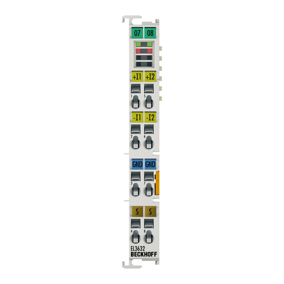
Error 1/2 Open circuit error Connection EL3632 Fig. 33: Connection Note: Terminal point 2 and 6 (- Input of the channels) are internally linked. Thus, a multichannel IEPE sensor can be connected, that supports one GND returning wire only. If a three channel sensor (3 axis, triaxis) will be connected via two terminals, each GND and respectively each -Input have to bridged. - Page 42 Ground (internally connected with terminal point 7) Shield Shield (internally connected to terminal point 8) + Input 2 + Input 2 - Input 2 - Input 2 Ground (internally connected with terminal point 3) Shield Shield (internally connected to terminal point 4) Version: 2.8 EL3632...
-
Page 43: Commissioning
• "offline": The configuration can be customized by adding and positioning individual components. These can be selected from a directory and configured. ◦ The procedure for offline mode can be found under http://infosys.beckhoff.com: TwinCAT 2 → TwinCAT System Manager → IO - Configuration → Adding an I/O Device •... -
Page 44: Fig. 34 Relationship Between User Side (Commissioning) And Installation
• Linked via the X001 port (RJ-45): EK1100 EtherCAT Coupler • Connected to the EK1100 EtherCAT coupler on the right (E-bus): EL2008 (8-channel digital output terminal 24 V DC; 0.5 A) • (Optional via X000: a link to an external PC for the user interface) Version: 2.8 EL3632... -
Page 45: Fig. 35 Control Configuration With Embedded Pc, Input (El1004) And Output (El2008)
Note that all combinations of a configuration are possible; for example, the EL1004 terminal could also be connected after the coupler, or the EL2008 terminal could additionally be connected to the CX2040 on the right, in which case the EK1100 coupler wouldn’t be necessary. EL3632 Version: 2.8... -
Page 46: Fig. 36 Initial Twincat 2 User Interface
If the intention is to address the TwinCAT runtime environment installed on a PLC as development environment remotely from another system, the target system must be made known first. In the menu under "Actions" → "Choose Target System...", via the symbol " " or the "F8" key, open the following window: Version: 2.8 EL3632... -
Page 47: Fig. 37 Selection Of The Target System
Fig. 38: Specify the PLC for access by the TwinCAT System Manager: selection of the target system Once the target system has been entered, it is available for selection as follows (a password may have to be entered): After confirmation with "OK" the target system can be accessed via the System Manager. EL3632 Version: 2.8... -
Page 48: Fig. 39 Select "Scan Devices
Confirm the message "Find new boxes", in order to determine the terminals connected to the devices. "Free Run" enables manipulation of input and output values in "Config mode" and should also be acknowledged. Based on the sample configuration [} 44] described at the beginning of this section, the result is as follows: Version: 2.8 EL3632... - Page 49 TwinCAT PLC Control is the development environment for the creation of the controller in different program environments: TwinCAT PLC Control supports all languages described in IEC 61131-3. There are two text- based languages and three graphical languages. • Text-based languages ◦ Instruction List (IL) EL3632 Version: 2.8...
- Page 50 The following section refers to Structured Text (ST). After starting TwinCAT PLC Control, the following user interface is shown for an initial project: Fig. 43: TwinCAT PLC Control after startup Sample variables and a sample program have been created and stored under the name "PLC_example.pro": Version: 2.8 EL3632...
- Page 51 Manager has been notified, the warning no longer appears. First, integrate the TwinCAT PLC Control project in the System Manager via the context menu of the PLC configuration; right-click and select "Append PLC Project…": Fig. 45: Appending the TwinCAT PLC Control project EL3632 Version: 2.8...
- Page 52 "PLC_example" and via "Modify Link..." "Standard": Fig. 47: Creating the links between PLC variables and process objects In the window that opens, the process object for the variable “bEL1004_Ch4” of type BOOL can be selected from the PLC configuration tree: Version: 2.8 EL3632...
- Page 53 The links can also be checked by selecting a "Goto Link Variable” from the context menu of a variable. The object opposite, in this case the PDO, is automatically selected: EL3632 Version: 2.8...
- Page 54 The PLC system can then be started as described below. Starting the controller Starting from a remote system, the PLC control has to be linked with the Embedded PC over Ethernet via "Online" → “Choose Run-Time System…": Version: 2.8 EL3632...
- Page 55 This results in the message "No program on the controller! Should the new program be loaded?", which should be acknowledged with "Yes". The runtime environment is ready for the program start: EL3632 Version: 2.8...
- Page 56 (cf. "TwinCAT System Manager" of TwinCAT 2) for communication with the electromechanical components. After successful installation of the TwinCAT system on the PC to be used for development, TwinCAT 3 (shell) displays the following user interface after startup: Version: 2.8 EL3632...
- Page 57 First create a new project via (or under "File"→“New"→ "Project…"). In the following dialog make the corresponding entries as required (as shown in the diagram): Fig. 54: Create new TwinCAT project The new project is then available in the project folder explorer: EL3632 Version: 2.8...
- Page 58 If the intention is to address the TwinCAT runtime environment installed on a PLC as development environment remotely from another system, the target system must be made known first. Via the symbol in the menu bar: expand the pull-down menu: and open the following window: Fig. 56: Selection dialog: Choose the target system Version: 2.8 EL3632...
- Page 59 The TwinCAT System Manager may first have to be set to "Config mode" via or via the menu "TwinCAT" → "Restart TwinCAT (Config mode)". Fig. 58: Select "Scan" Confirm the warning message, which follows, and select "EtherCAT" in the dialog: EL3632 Version: 2.8...
- Page 60 The whole process consists of two stages, which may be performed separately (first determine the devices, then determine the connected elements such as boxes, terminals, etc.). A scan can also be initiated by selecting "Device ..." from the context menu, which then reads the elements present in the configuration below: Version: 2.8 EL3632...
- Page 61 The following section refers to Structured Text (ST). In order to create a programming environment, a PLC subproject is added to the project sample via the context menu of "PLC" in the project folder explorer by selecting "Add New Item….": EL3632 Version: 2.8...
- Page 62 Fig. 63: Specifying the name and directory for the PLC programming environment The "Main" program, which already exists by selecting "Standard PLC project", can be opened by double- clicking on "PLC_example_project" in "POUs”. The following user interface is shown for an initial project: Version: 2.8 EL3632...
- Page 63 Commissioning Fig. 64: Initial "Main" program of the standard PLC project To continue, sample variables and a sample program have now been created: EL3632 Version: 2.8...
- Page 64 "Assignments" in the project folder explorer: Assigning variables Via the menu of an instance - variables in the "PLC” context, use the "Modify Link…" option to open a window for selecting a suitable process object (PDO) for linking: Version: 2.8 EL3632...
- Page 65 4 of the EL1004 terminal is selected for linking. In contrast, the checkbox "All types" must be ticked for creating the link for the output variables, in order to allocate a set of eight separate output bits to a byte variable. The following diagram shows the whole process: EL3632 Version: 2.8...
- Page 66 PDO, it is possible to allocate this a set of bit-standardised variables (type "BOOL"). Here, too, a "Goto Link Variable” from the context menu of a PDO can be executed in the other direction, so that the respective PLC instance can then be selected. Version: 2.8 EL3632...
- Page 67 Fig. 71: TwinCAT development environment (VS shell): logged-in, after program startup The two operator control elements for stopping and logout result in the required action (accordingly also for stop "Shift + F5", or both actions can be selected via the PLC menu). EL3632 Version: 2.8...
-
Page 68: Twincat 2
5.2.1 Installation of the TwinCAT real-time driver In order to assign real-time capability to a standard Ethernet port of an IPC controller, the Beckhoff real-time driver has to be installed on this port under Windows. This can be done in several ways. One option is described here. - Page 69 Alternatively an EtherCAT-device can be inserted first of all as described in chapter Offline configuration creation, section “Creating the EtherCAT device” [} 79] in order to view the compatible ethernet ports via its EtherCAT properties (tab „Adapter“, button „Compatible Devices…“): EL3632 Version: 2.8...
- Page 70 After the installation the driver appears activated in the Windows overview for the network interface (Windows Start → System Properties → Network) Fig. 76: Windows properties of the network interface A correct setting of the driver could be: Version: 2.8 EL3632...
- Page 71 Commissioning Fig. 77: Exemplary correct driver setting for the Ethernet port Other possible settings have to be avoided: EL3632 Version: 2.8...
- Page 72 Commissioning Fig. 78: Incorrect driver settings for the Ethernet port Version: 2.8 EL3632...
- Page 73 DHCP. In this way the delay associated with the DHCP client for the Ethernet port assigning itself a default IP address in the absence of a DHCP server is avoided. A suitable address space is 192.168.x.x, for example. Fig. 79: TCP/IP setting for the Ethernet port EL3632 Version: 2.8...
-
Page 74: Notes Regarding Esi Device Description
The files are read (once) when a new System Manager window is opened, if they have changed since the last time the System Manager window was opened. A TwinCAT installation includes the set of Beckhoff ESI files that was current at the time when the TwinCAT build was created. - Page 75 1018 in the configuration. This is also stated by the Beckhoff compatibility rule. Refer in particular to the chapter ‘General notes on the use of Beckhoff EtherCAT IO components’ and for manual configuration to the chapter ‘Offline configuration creation’ [} 79].
- Page 76 Faulty ESI file If an ESI file is faulty and the System Manager is unable to read it, the System Manager brings up an information window. Fig. 85: Information window for faulty ESI file (left: TwinCAT 2; right: TwinCAT 3) Version: 2.8 EL3632...
- Page 77 Commissioning Reasons may include: • Structure of the *.xml does not correspond to the associated *.xsd file → check your schematics • Contents cannot be translated into a device description → contact the file manufacturer EL3632 Version: 2.8...
-
Page 78: Twincat Esi Updater
Commissioning 5.2.3 TwinCAT ESI Updater For TwinCAT 2.11 and higher, the System Manager can search for current Beckhoff ESI files automatically, if an online connection is available: Fig. 86: Using the ESI Updater (>= TwinCAT 2.11) The call up takes place under: “Options” → "Update EtherCAT Device Descriptions"... -
Page 79: Offline Configuration Creation
EL6601/EL6614 terminal select “EtherCAT Automation Protocol via EL6601”. Fig. 89: Selecting the EtherCAT connection (TwinCAT 2.11, TwinCAT 3) Then assign a real Ethernet port to this virtual device in the runtime system. Fig. 90: Selecting the Ethernet port EL3632 Version: 2.8... - Page 80 Fig. “Selection dialog for new EtherCAT device”. If the preceding device has several free ports (e.g. EK1122 or EK1100), the required port can be selected on the right-hand side (A). Overview of physical layer • “Ethernet”: cable-based 100BASE-TX: EK couplers, EP boxes, devices with RJ45/M8/M12 connector Version: 2.8 EL3632...
- Page 81 (i.e. highest) revision and therefore the latest state of production is displayed in the selection dialog for Beckhoff devices. To show all device revisions available in the system as ESI descriptions tick the “Show Hidden Devices” check box, see Fig. “Display of previous revisions”.
- Page 82 If current ESI descriptions are available in the TwinCAT system, the last revision offered in the selection dialog matches the Beckhoff state of production. It is recommended to use the last device revision when creating a new configuration, if current Beckhoff devices are used in the real application. Older revisions should only be used if older devices from stock are to be used in the application.
- Page 83 Commissioning Fig. 97: EtherCAT terminal in the TwinCAT tree (left: TwinCAT 2; right: TwinCAT 3) EL3632 Version: 2.8...
-
Page 84: Online Configuration Creation
This scan mode attempts to find not only EtherCAT devices (or Ethernet ports that are usable as such), but also NOVRAM, fieldbus cards, SMB etc. However, not all devices can be found automatically. Fig. 100: Note for automatic device scan (left: TwinCAT 2; right: TwinCAT 3) Version: 2.8 EL3632... - Page 85 [} 89] with the defined initial configuration.Background: since Beckhoff occasionally increases the revision version of the delivered products for product maintenance reasons, a configuration can be created by such a scan which (with an identical machine construction) is identical according to the device list;...
- Page 86 Likewise, A might create spare parts stores worldwide for the coming series-produced machines with EL2521-0025-1018 terminals. After some time Beckhoff extends the EL2521-0025 by a new feature C. Therefore the FW is changed, outwardly recognizable by a higher FW version and a new revision -1019. Nevertheless the new device naturally supports functions and interfaces of the predecessor version(s);...
- Page 87 Fig. 109: Displaying of “Free Run” and “Config Mode” toggling right below in the status bar Fig. 110: TwinCAT can also be switched to this state by using a button (left: TwinCAT 2; right: TwinCAT 3) The EtherCAT system should then be in a functional cyclic state, as shown in Fig. “Online display example”. EL3632 Version: 2.8...
- Page 88 The connections and devices should be checked in a targeted manner, e.g. via the emergency scan. Then re-run the scan. Fig. 112: Faulty identification In the System Manager such devices may be set up as EK0000 or unknown devices. Operation is not possible or meaningful. Version: 2.8 EL3632...
- Page 89 A ‘ChangeTo’ or ‘Copy’ should only be carried out with care, taking into consideration the Beckhoff IO compatibility rule (see above). The device configuration is then replaced by the revision found; this can affect the supported process data and functions.
- Page 90 If current ESI descriptions are available in the TwinCAT system, the last revision offered in the selection dialog matches the Beckhoff state of production. It is recommended to use the last device revision when creating a new configuration, if current Beckhoff devices are used in the real application. Older revisions should only be used if older devices from stock are to be used in the application.
- Page 91 This function is preferably to be used on AX5000 devices. Change to Alternative Type The TwinCAT System Manager offers a function for the exchange of a device: Change to Alternative Type Fig. 118: TwinCAT 2 Dialog Change to Alternative Type EL3632 Version: 2.8...
-
Page 92: Ethercat Subscriber Configuration
Comment Here you can add a comment (e.g. regarding the system). Disabled Here you can deactivate the EtherCAT device. Create symbols Access to this EtherCAT slave via ADS is only available if this control box is activated. Version: 2.8 EL3632... - Page 93 CANopen process data objects (Process Data Objects, PDOs). The user can select a PDO via PDO assignment and modify the content of the individual PDO via this dialog, if the EtherCAT slave supports this function. EL3632 Version: 2.8...
- Page 94 For Beckhoff EtherCAT EL, ES, EM, EJ and EP slaves the following applies in general: • The input/output process data supported by the device are defined by the manufacturer in the ESI/XML description.
- Page 95 (CoE) or Servo drive over EtherCAT protocol. This tab indicates which download requests are sent to the mailbox during startup. It is also possible to add new mailbox requests to the list display. The download requests are sent to the slave in the same order as they are shown in the list. EL3632 Version: 2.8...
- Page 96 (CoE) protocol. This dialog lists the content of the object list of the slave (SDO upload) and enables the user to modify the content of an object from this list. Details for the objects of the individual EtherCAT devices can be found in the device-specific object descriptions. Version: 2.8 EL3632...
- Page 97 The Update list button updates all objects in the displayed list Auto Update If this check box is selected, the content of the objects is updated automatically. Advanced The Advanced button opens the Advanced Settings dialog. Here you can specify which objects are displayed in the list. EL3632 Version: 2.8...
- Page 98 Offline - via EDS File If this option button is selected, the list of the objects included in the object list is read from an EDS file provided by the user. „Online“ tab Fig. 127: „Online“ tab Version: 2.8 EL3632...
- Page 99 Fig. 128: "DC" tab (Distributed Clocks) Operation Mode Options (optional): • FreeRun • SM-Synchron • DC-Synchron (Input based) • DC-Synchron Advanced Settings… Advanced settings for readjustment of the real time determinant TwinCAT- clock Detailed information to Distributed Clocks are specified on http://infosys.beckhoff.com: EL3632 Version: 2.8...
- Page 100 Sync Manager! Consequently, this PDO cannot be deleted from the PDO Assignment list Sync Manager to which this PDO is assigned. If this entry is empty, this PDO does not take part in the process data traffic. Sync unit to which this PDO is assigned. Version: 2.8 EL3632...
-
Page 101: General Notes - Ethercat Slave Application
Those diagnostic elements that are helpful to the controlling task for diagnosis that is accurate for the current cycle when in operation (not during commissioning) are discussed below. Fig. 129: Selection of the diagnostic information of an EtherCAT Slave EL3632 Version: 2.8... - Page 102 Fig. “Basic EtherCAT Slave Diagnosis in the PLC” shows an example of an implementation of basic EtherCAT Slave Diagnosis. A Beckhoff EL3102 (2-channel analogue input terminal) is used here, as it offers both the communication diagnosis typical of a slave and the functional diagnosis that is specific to a channel.
- Page 103 The CoE parameter directory (CanOpen-over-EtherCAT) is used to manage the set values for the slave concerned. Changes may, in some circumstances, have to be made here when commissioning a relatively complex EtherCAT Slave. It can be accessed through the TwinCAT System Manager, see Fig. “EL3102, CoE directory”: EL3632 Version: 2.8...
-
Page 104: Fig. 131 El3102, Coe Directory
Commissioning interfaces are being introduced as part of an ongoing process for EL/EP EtherCAT devices. These are available in TwinCAT System Managers from TwinCAT 2.11R2 and above. They are integrated into the System Manager through appropriately extended ESI configuration files. Version: 2.8 EL3632... -
Page 105: Fig. 132 Example Of Commissioning Aid For A El3204
The target state wanted by the user, and which is brought about automatically at start-up by TwinCAT, can be set in the System Manager. As soon as TwinCAT reaches the status RUN, the TwinCAT EtherCAT Master will approach the target states. EL3632 Version: 2.8... -
Page 106: Fig. 133 Default Behaviour Of The System Manager
Fig. 133: Default behaviour of the System Manager In addition, the target state of any particular Slave can be set in the "Advanced Settings" dialogue; the standard setting is again OP. Fig. 134: Default target state in the Slave Version: 2.8 EL3632... -
Page 107: Fig. 135 Plc Function Blocks
The pre-calculated theoretical maximum E-Bus current is displayed in the TwinCAT System Manager as a column value. A shortfall is marked by a negative total amount and an exclamation mark; a power feed terminal is to be placed before such a position. EL3632 Version: 2.8... -
Page 108: Fig. 136 Illegally Exceeding The E-Bus Current
Fig. 137: Warning message for exceeding E-Bus current NOTE Caution! Malfunction possible! The same ground potential must be used for the E-Bus supply of all EtherCAT terminals in a terminal block! Version: 2.8 EL3632... -
Page 109: Oversampling Terminals/Boxes And Twincat Scope
• Beckhoff: the device/ the terminal/box read of the used ADC (could be a deltaSigma ADC also) digital sample data n-times more than the PLC/ bus cycle time is set and transfers every sample to the control –... -
Page 110: Twincat 3 Procedure
EL3783 EL3783-0000-0017 EL3773 EL3773-0000-0019 EL3751 EL3742 EL3702 EL3632 EL2262 EL1262-0050 EL1262 EP3632-0001 EPP3632-0001 Recording a PLC Variable with the TwinCAT 3 – ScopeView By a precondition of an already created TwinCAT 3 – project and a connected PLC with an oversampling able terminal/box within the configuration it will be illustrated how an oversampling variable can be represented by the Scope (as a standard part of the TwinCAT 3 environment). -
Page 111: Fig. 139 Adding A Scope Project Into An Already Existing Project
TwinCAT 3 development environment within the section PLC under “..Instance”. The following illustration shows extracts of the solution explorer on the right. As an example that linking of an array variable to a set of oversampling process data is represented herewith: EL3632 Version: 2.8... -
Page 112: Fig. 140 Representation Of A Created Plc Array Variable („Aui_Samples") To Link With Oversampling Pdos Of El3773
When a POU is not needed onto the particular system, a referenced variable could be applied via a free task also. If a free task is not existing still yet, it can be created by a right-click to “Task” of the project within SYSTEM with “Add New Item…”. Fig. 141: Insertion of a free task Version: 2.8 EL3632... -
Page 113: Fig. 142 Task Property "Create Symbols" Must Be Activated
Step 3: Linking an array variable with an oversampling PDO By right click on “MAIN.aUI_Samples” (according to the last preceding paragraph Step 2a) or rather “Var 1” (according to the last preceding paragraph Step 2b) within the Solution Explorer a window opens to select the process data: EL3632 Version: 2.8... -
Page 114: Fig. 144 Set Up The Link Of The Plc Array Variable (Left: For The Last Preceding Paragraph Step 2A, Right: For The Last Preceding Paragraph Step 2B)
), so the array variable will be visible for the target browser of the scope for being selected. Thereby the drop down menu will be opened by right clicking on “Axis” (A) for selection of the scope features (B): Version: 2.8 EL3632... -
Page 115: Fig. 146 Selection Of The Oversampling Variable With The Target Browser
If „ROUTES“ don’t offer a possibility for selection of the provided variables, the corresponding port should be declared for the target browser: Using “Add symbol” displays the variable "aUI_Samples“ below “axis” within the scope project of the solution explorer directly. EL3632 Version: 2.8... -
Page 116: Fig. 148 Example Of Recording A Sine Signal With 10 X Oversampling At 1 Ms Measurement Cycle Time
In former TwinCAT 3 versions (or a lower revision as specified in the table [} 110] above) the oversampling PDO of the respective oversampling able terminal/box can be made visible for the ScopeView by activation of the ADS server. Version: 2.8 EL3632... -
Page 117: Fig. 149 Activation Of The Ads Server Of The Ethercat Device (Twincat 3)
„Create symbols“ then (the port entry is done automatically). Thereby it is possible to access process data without an embedded POU and accordingly without a linked variable: Fig. 150: Direct access to PDOs of the terminal by ScopeView EL3632 Version: 2.8... -
Page 118: Twincat 2 Procedure
PDO (according to an array variable usually). In this case it can be changed by the channel properties: TwinCAT 3: Activate the ADS Server of an EtherCAT device Also see Beckhoff Information System: 5.4.2 TwinCAT 2 procedure The TwinCAT Scope2 supports the import and display of oversampling process data such as is used by oversampling-able terminals/boxes. -
Page 119: Fig. 151 Plc Declaration
Fig. 153: Add Variable Type An ARRAY variable of the type as known by the PLC must be created in the syntax as known from the PLC. In this example an array of 0..9 of type INT, i.e. with 10 fields. EL3632 Version: 2.8... -
Page 120: Fig. 154 Definition Of The Variable Type
It appears in the overview, sorted according to bit size. Fig. 155: Overview of declared types In this example the variable Var152 is created. It can now be linked with the PDO-Array of the respective channel of the terminal/box. Version: 2.8 EL3632... -
Page 121: Fig. 156 Linking
This array variable must be defined and created manually; see above [} 119]. You can now browse to the variable concerned in the Scope2. EL3632 Version: 2.8... -
Page 122: Fig. 159 Variable Browser Up To The Array Var152
In order to check that individual oversampling values are really being logged, the Marks can be activated in the Scope2. Please observe the interrelationships between task cycle time, sampling time of the Scope2 channel and oversampling factor. Version: 2.8 EL3632... -
Page 123: Fig. 162 Activation Of The Marks
Commissioning Fig. 162: Activation of the marks An additional example illustrates the following image by representation of an oversampling – variable from the EL3751 with 10 x oversampling: EL3632 Version: 2.8... -
Page 124: Fig. 163 Illustration Of A 10 X Oversampling Variable Of The El3751 By The Scope2
PDO of the respective oversampling able terminal/box can be made visible for the Scope2 by activation of the ADS server. So the creation of a PLC variable can be disclaimed as well. Therefore the ADS server of the EtherCAT Device where the oversampling able terminal/box is connected with have to be activated. Version: 2.8 EL3632... -
Page 125: Fig. 164 Activation Of The Ads Server Of The Ethercat Device (Twincat 2)
„Create symbols“ then (the port entry is done automatically). Thus with the Scope2 process data can be accessed via the target browser without an embedded POU and without a variable reference respectively. Fig. 165: Direct access of the Scope2 to the terminal's PDOs EL3632 Version: 2.8... -
Page 126: Fig. 166 Automatically Calculated Array Variable (Red) In The Scope2
TS3300 | TwinCAT Scope 2 → Annex → Oversampling record: Beckhoff TwinCAT supports the Scope2 with some oversampling devices in a special way by automatically calculating a special ADS array symbol in the background, which appears in the Scope2 in the variable browser. -
Page 127: Basics And Commissioning
Fig. 168: Sampling times in relation to cycle times and oversampling Configurations that demand sampling times not divisible by 500 ns are not supported. Setting the sampling rate 1. Select the terminal/box in the TwinCAT tree 2. Select the “DC/Oversampling” tab 3. Select the operating mode (1/2-channel) EL3632 Version: 2.8... -
Page 128: Fig. 169 Setting The Sampling Rate In Twincat
0 to 0 and at the end to the number of entered values. The sync interrupts should be parameterized as follows: Sync0: CycleTime/Oversampling Factor, set Enable; Sync1 Cycle Unit Cycle, set Enable. The master must support Distributed Clocks. Selection of the process data No longer necessary with TwinCAT. Version: 2.8 EL3632... -
Page 129: Fig. 170 Filter Structure
Level 5: b = 1/65536 Level 6: b = 1/131072 (128 k) Level 7: b = 1/262144 (256 k) Level 8: b = 1/524288 (512 k). Calibration The input values can be calibrated by means of manufacturer or user values: EL3632 Version: 2.8... - Page 130 Sample: A sensor with a sensitivity S of 100 mV / g (10.2 mV/(m/s^2) ) is connected to a synchronized EL3632/EP3632 (15-bit resolution + sign, +/- 5 V). In the process data an amplitude of 1507 is measured. a = Y...
- Page 131 If only the first channel is activated, the red LED for the second channel is disabled in SAFEOP and OP state. Multi-channel IEPE sensors with a common GND can be connected to the EL3632 if the GND and AGND connection points are connected via an external bridge: Unused inputs Unused inputs must not be short-circuited.
- Page 132 Active offset adjust- ENUM Disabled (0) Automatic offset calculation [} 129] ment 0: Disabled 1: Level 1 2: Level 2 3: Level 3 4: Level 4 5: Level 5 6: Level 6 7: Level 7 8: Level 8 Version: 2.8 EL3632...
- Page 133 Validity of the data of the associated TxPDO (0 = valid, 1 BOOLEAN 0x00 (0 = invalid). 60n0:10 TxPDO Toggle A new measured value is available (if the toggle bit was BOOLEAN 0x00 (0 changed). Status bits may be changed independent from the toggle bit. EL3632 Version: 2.8...
- Page 134 EtherCAT XML Device Description The display matches that of the CoE objects from the EtherCAT XML Device Description. We rec- ommend downloading the latest XML file from the download area of the Beckhoff website and in- stalling it according to installation instructions.
- Page 135 Index (hex) Name Meaning Data type Flags Default 1008:0 Device name Device name of the EtherCAT slave STRING EL3632 Index 1009 Hardware version Index (hex) Name Meaning Data type Flags Default 1009:0 Hardware version Hardware version of the EtherCAT slave...
- Page 136 Index (hex) Name Meaning Data type Flags Default 1A05:0 Analog Input TxPDO- PDO Mapping TxPDO 6 UINT8 0x01 (1 MapSamples 5 Ch.1 1A05:01 SubIndex 001 1. PDO Mapping entry (object 0x6005 (Sample 5), entry UINT32 0x6001:05, 16 0x01 (Value)) Version: 2.8 EL3632...
- Page 137 Index (hex) Name Meaning Data type Flags Default 1A0D:0 Analog Input TxPDO- PDO Mapping TxPDO 14 UINT8 0x01 (1 MapSamples 13 Ch.1 1A0D:01 SubIndex 001 1. PDO Mapping entry (object 0x600D (Sample 13), entry UINT32 0x6001:0D, 0x01 (Value)) EL3632 Version: 2.8...
- Page 138 Index (hex) Name Meaning Data type Flags Default 1A15:0 Analog Input TxPDO- PDO Mapping TxPDO 22 UINT8 0x01 (1 MapSamples 21 Ch.1 1A15:01 SubIndex 001 1. PDO Mapping entry (object 0x6011 (Sample 17), entry UINT32 0x6001:15, 16 0x01 (Value)) Version: 2.8 EL3632...
- Page 139 Index (hex) Name Meaning Data type Flags Default 1A1D:0 Analog Input TxPDO- PDO Mapping TxPDO 30 UINT8 0x01 (1 MapSamples 29 Ch.1 1A1D:01 SubIndex 001 1. PDO Mapping entry (object 0x6002 (Samples), entry UINT32 0x6001:1D, 0x1C ()) EL3632 Version: 2.8...
- Page 140 Index (hex) Name Meaning Data type Flags Default 1A25:0 Analog Input TxPDO- PDO Mapping TxPDO 38 UINT8 0x01 (1 MapSamples 37 Ch.1 1A25:01 SubIndex 001 1. PDO Mapping entry (object 0x6002 (Samples), entry UINT32 0x6001:25, 16 0x24 ()) Version: 2.8 EL3632...
- Page 141 Index (hex) Name Meaning Data type Flags Default 1A2D:0 Analog Input TxPDO- PDO Mapping TxPDO 46 UINT8 0x01 (1 MapSamples 45 Ch.1 1A2D:01 SubIndex 001 1. PDO Mapping entry (object 0x6002 (Samples), entry UINT32 0x6001:2D, 0x2C ()) EL3632 Version: 2.8...
- Page 142 7. PDO Mapping entry (object 0x1C33 (SM input param- UINT32 0x1C33:20, 1 eter), entry 0x20 (Sync error)) 1A40:08 SubIndex 008 8. PDO Mapping entry (object 0x1840, entry 0x07) UINT32 0x1840:07, 1 1A40:09 SubIndex 009 9. PDO Mapping entry (object 0x1840, entry 0x09) UINT32 0x1840:09, 1 Version: 2.8 EL3632...
- Page 143 Index (hex) Name Meaning Data type Flags Default 1A48:0 Analog Input TxPDO- PDO Mapping TxPDO 73 UINT8 0x01 (1 MapSamples 8 Ch.2 1A48:01 SubIndex 001 1. PDO Mapping entry (object 0x6012 (Samples), entry UINT32 0x6011:08, 16 0x08 ()) EL3632 Version: 2.8...
- Page 144 Index (hex) Name Meaning Data type Flags Default 1A50:0 Analog Input TxPDO- PDO Mapping TxPDO 81 UINT8 0x01 (1 MapSamples 16 Ch.2 1A50:01 SubIndex 001 1. PDO Mapping entry (object 0x6012 (Samples), entry UINT32 0x6011:10, 16 0x0F ()) Version: 2.8 EL3632...
- Page 145 Index (hex) Name Meaning Data type Flags Default 1A58:0 Analog Input TxPDO- PDO Mapping TxPDO 89 UINT8 0x01 (1 MapSamples 24 Ch.2 1A58:01 SubIndex 001 1. PDO Mapping entry (object 0x6012 (Samples), entry UINT32 0x6011:18, 16 0x07 ()) EL3632 Version: 2.8...
- Page 146 Index (hex) Name Meaning Data type Flags Default 1A60:0 Analog Input TxPDO- PDO Mapping TxPDO 97 UINT8 0x01 (1 MapSamples 32 Ch.2 1A60:01 SubIndex 001 1. PDO Mapping entry (object 0x6012 (Samples), entry UINT32 0x6011:20, 16 0x0F ()) Version: 2.8 EL3632...
- Page 147 Index (hex) Name Meaning Data type Flags Default 1A68:0 Analog Input TxPDO- PDO Mapping TxPDO 105 UINT8 0x01 (1 MapSamples 40 Ch.2 1A68:01 SubIndex 001 1. PDO Mapping entry (object 0x6012 (Samples), entry UINT32 0x6011:28, 16 0x17 ()) EL3632 Version: 2.8...
- Page 148 Index (hex) Name Meaning Data type Flags Default 1A70:0 Analog Input TxPDO- PDO Mapping TxPDO 113 UINT8 0x01 (1 MapSamples 48 Ch.2 1A70:01 SubIndex 001 1. PDO Mapping entry (object 0x6012 (Samples), entry UINT32 0x6011:30, 16 0x1F ()) Version: 2.8 EL3632...
- Page 149 1C13:03 Subindex 003 3. allocated TxPDO (contains the index of the associated UINT16 0x0000 (0 TxPDO mapping object) 1C13:68 Subindex 104 104. allocated TxPDO (contains the index of the associ- UINT16 0x0000 (0 ated TxPDO mapping object) EL3632 Version: 2.8...
- Page 150 Index distance of the objects of the individual channels UINT16 0x0010 (16 tance F000:02 Maximum number of Number of channels UINT16 0x0003 (3 modules Index F008 Code word Index (hex) Name Meaning Data type Flags Default F008:0 Code word reserved UINT32 0x00000000 Version: 2.8 EL3632...
-
Page 151: Update Of The Terminal
0x0000012C (300 F010:02 SubIndex 002 Profile AI UINT32 0x0000012C (300 F010:03 SubIndex 003 Profile AI UINT32 0x0000012C (300 5.5.2 Update of the terminal Information on updating the terminal description can be found in the chapter Firmware-Update [} 197]. EL3632 Version: 2.8... -
Page 152: Coe Object Description
EtherCAT XML Device Description The display matches that of the CoE objects from the EtherCAT XML Device Description. We rec- ommend downloading the latest XML file from the download area of the Beckhoff website and in- stalling it according to installation instructions. - Page 153 80nF:02 Calibration gain (gain Gain (vendor calibration), gain 1 INT16 0x0000 (0 80nF:03 Calibration offset Offset (vendor calibration), gain 20 INT16 0x0000 (0 (gain 20) 80nF:04 Calibration gain (gain Gain (vendor calibration), gain 20 INT16 0x0000 (0 EL3632 Version: 2.8...
- Page 154 00 00 00 00 Index 6021 Sample Count Index (hex) Name Meaning Data type Flags Default 6021:0 Sample Count Maximum subindex UINT8 0x01 (1 6021:01 Sample Count Sample counter (incremented with each ADC value) UINT16 RO P 0x0000 (0 Version: 2.8 EL3632...
-
Page 155: Standard Objects And Pdo Mapping
EtherCAT XML Device Description The display matches that of the CoE objects from the EtherCAT XML Device Description. We rec- ommend downloading the latest XML file from the download area of the Beckhoff website and in- stalling it according to installation instructions. - Page 156 Index (hex) Name Meaning Data type Flags Default 1A02:0 Analog Input TxPDO- PDO Mapping TxPDO 3 UINT8 0x01 (1 MapSamples 2 Ch.1 1A02:01 SubIndex 001 1. PDO Mapping entry (object 0x6002 (Sample 2), entry UINT32 0x6001:02, 16 0x01 (Value)) Version: 2.8 EL3632...
- Page 157 Index (hex) Name Meaning Data type Flags Default 1A0A:0 Analog Input TxPDO- PDO Mapping TxPDO 11 UINT8 0x01 (1 MapSamples 10 Ch.1 1A0A:01 SubIndex 001 1. PDO Mapping entry (object 0x600A (Sample 10), entry UINT32 0x6001:0A, 16 0x01 (Value)) EL3632 Version: 2.8...
- Page 158 Index (hex) Name Meaning Data type Flags Default 1A12:0 Analog Input TxPDO- PDO Mapping TxPDO 19 UINT8 0x01 (1 MapSamples 18 Ch.1 1A12:01 SubIndex 001 1. PDO Mapping entry (object 0x6002 (Sample 2), entry UINT32 0x6001:12, 16 0x01 (Value)) Version: 2.8 EL3632...
- Page 159 Index (hex) Name Meaning Data type Flags Default 1A1A:0 Analog Input TxPDO- PDO Mapping TxPDO 27 UINT8 0x01 (1 MapSamples 26 Ch.1 1A1A:01 SubIndex 001 1. PDO Mapping entry (object 0x6002 (Samples), entry UINT32 0x6001:1A, 16 0x19 ()) EL3632 Version: 2.8...
- Page 160 Index (hex) Name Meaning Data type Flags Default 1A22:0 Analog Input TxPDO- PDO Mapping TxPDO 35 UINT8 0x01 (1 MapSamples 34 Ch.1 1A22:01 SubIndex 001 1. PDO Mapping entry (object 0x6002 (Samples), entry UINT32 0x6001:22, 16 0x21 ()) Version: 2.8 EL3632...
- Page 161 Index (hex) Name Meaning Data type Flags Default 1A2A:0 Analog Input TxPDO- PDO Mapping TxPDO 43 UINT8 0x01 (1 MapSamples 42 Ch.1 1A2A:01 SubIndex 001 1. PDO Mapping entry (object 0x6002 (Samples), entry UINT32 0x6001:2A, 16 0x29 ()) EL3632 Version: 2.8...
- Page 162 Index (hex) Name Meaning Data type Flags Default 1A32:0 Analog Input TxPDO- PDO Mapping TxPDO 51 UINT8 0x01 (1 MapSamples 50 Ch.1 1A32:01 SubIndex 001 1. PDO Mapping entry (object 0x6002 (Samples), entry UINT32 0x6001:32, 16 0x31 ()) Version: 2.8 EL3632...
- Page 163 Index (hex) Name Meaning Data type Flags Default 1A45:0 Analog Input TxPDO- PDO Mapping TxPDO 70 UINT8 0x01 (1 MapSamples 5 Ch.2 1A45:01 SubIndex 001 1. PDO Mapping entry (object 0x6012 (Samples), entry UINT32 0x6011:05, 16 0x05 ()) EL3632 Version: 2.8...
- Page 164 Index (hex) Name Meaning Data type Flags Default 1A4D:0 Analog Input TxPDO- PDO Mapping TxPDO 78 UINT8 0x01 (1 MapSamples 13 Ch.2 1A4D:01 SubIndex 001 1. PDO Mapping entry (object 0x6012 (Samples), entry UINT32 0x6011:0D, 0x0D ()) Version: 2.8 EL3632...
- Page 165 Index (hex) Name Meaning Data type Flags Default 1A55:0 Analog Input TxPDO- PDO Mapping TxPDO 86 UINT8 0x01 (1 MapSamples 21 Ch.2 1A55:01 SubIndex 001 1. PDO Mapping entry (object 0x6012 (Samples), entry UINT32 0x6011:15, 16 0x14 ()) EL3632 Version: 2.8...
- Page 166 Index (hex) Name Meaning Data type Flags Default 1A5D:0 Analog Input TxPDO- PDO Mapping TxPDO 94 UINT8 0x01 (1 MapSamples 29 Ch.2 1A5D:01 SubIndex 001 1. PDO Mapping entry (object 0x6012 (Samples), entry UINT32 0x6011:1D, 0x0C ()) Version: 2.8 EL3632...
- Page 167 Index (hex) Name Meaning Data type Flags Default 1A65:0 Analog Input TxPDO- PDO Mapping TxPDO 102 UINT8 0x01 (1 MapSamples 37 Ch.2 1A65:01 SubIndex 001 1. PDO Mapping entry (object 0x6012 (Samples), entry UINT32 0x6011:25, 16 0x14 ()) EL3632 Version: 2.8...
- Page 168 Index (hex) Name Meaning Data type Flags Default 1A6D:0 Analog Input TxPDO- PDO Mapping TxPDO 110 UINT8 0x01 (1 MapSamples 45 Ch.2 1A6D:01 SubIndex 001 1. PDO Mapping entry (object 0x6012 (Samples), entry UINT32 0x6011:2D, 0x1C ()) Version: 2.8 EL3632...
- Page 169 Data type Flags Default 1A81:0 Analog Input Time- PDO Mapping TxPDO 130 UINT8 0x01 (1 stamp TxPDO-Map Cycle Count 1A81:01 SubIndex 001 1. PDO Mapping entry (object 0x6021 (CycleCount), en- UINT32 0x6021:01, 16 try 0x01 (Cycle Count)) EL3632 Version: 2.8...
- Page 170 1C13:03 Subindex 003 3. allocated TxPDO (contains the index of the associated UINT16 0x0000 (0 TxPDO mapping object) 1C13:68 Subindex 104 104. allocated TxPDO (contains the index of the associ- UINT16 0x0000 (0 ated TxPDO mapping object) Version: 2.8 EL3632...
- Page 171 Index distance of the objects of the individual channels UINT16 0x0010 (16 tance F000:02 Maximum number of Number of channels UINT16 0x0003 (3 modules Index F008 Code word Index (hex) Name Meaning Data type Flags Default F008:0 Code word reserved UINT32 0x00000000 EL3632 Version: 2.8...
-
Page 172: Notices On Analog Specifications
For analog I/O devices from Beckhoff the rule is that the limit with the largest value is chosen as the full scale value of the respective product (also called the reference value) and is given a positive sign. This applies to both symmetrical and asymmetrical measuring spans. -
Page 173: Temperature Coefficient Tk [Ppm/K]
A manufacturer can alleviate this by using components of a higher quality or by software means. The temperature coefficient, when indicated, specified by Beckhoff allows the user to calculate the expected measuring error outside the basic accuracy at 23 °C. -
Page 174: Single-Ended/Differential Typification
In particular this also applies to SE, even though the term suggest that only one wire is required. • The term "electrical isolation" should be clarified in advance. Beckhoff IO modules feature 1..8 or more analog channels; with regard to the channel connection a distinction is made in terms of: ◦... - Page 175 The property of electrical isolation indicates whether the channels are directly connected to each other. ◦ Beckhoff terminals/ boxes (and related product groups) always feature electrical isolation between the field/analog side and the bus/EtherCAT side. In other words, if two analog terminals/ boxes are not connected via the power contacts (cable), the modules are effectively electrically isolated.
-
Page 176: Fig. 173 2-Wire Connection
+signal can be connected to +supply or –signal to –supply. - Yes: then you can connect accordingly to a Beckhoff ‘single-ended’ input. - No: the Beckhoff ‘differential’ input for +Signal and –Signal is to be selected; +Supply and – Supply are to be connected via additional cables. - Page 177 Commissioning Fig. 174: Connection of externally supplied sensors Classification of the Beckhoff terminals/ boxes - Beckhoff 0/4-20 mA terminals/ boxes (and related product groups) are available as differential and single-ended terminals/ boxes (and related product groups): Single-ended Differential EL3x4x: 0-20 mA, EL3x5x: 4-20 mA; KL and related product EL3x1x: 0-20 mA, EL3x2x: 4-20 mA;...
- Page 178 Commissioning Single-ended Differential Fig. 175: 2-, 3- and 4-wire connection at single-ended and differential inputs Version: 2.8 EL3632...
-
Page 179: Common-Mode Voltage And Reference Ground (Based On Differential Inputs)
Reference ground samples for Beckhoff IO devices: 1. Internal AGND fed out: EL3102/EL3112, resistive connection between the channels 2. 0V power contact: EL3104/EL3114, resistive connection between the channels and AGND; AGND connected to 0V power contact with low-resistance 3. -
Page 180: Temporal Aspects Of Analog/Digital Conversion
The conversion of the constant electrical input signal to a value-discrete digital and machine-readable form takes place in the analog Beckhoff EL/KL/EP input modules with ADC (analog digital converter). Although different ADC technologies are in use, from a user perspective they all have a common characteristic: after the conversion a certain digital value is available in the controller for further processing. - Page 181 This is the “external” view of the “Beckhoff AI channel” system – internally the signal delay in particular is composed of different components: hardware, amplifier, conversion itself, data transport and processing.
- Page 182 A meaningful range must be selected for the test frequency, e.g. 1/20 of the maximum sampling rate. Fig. 180: Diagram signal delay (linear) 3. Additional Information May be provided in the specification, e.g. Version: 2.8 EL3632...
-
Page 183: Application Example
• Actual sampling rate of the ADC (if different from the channel sampling rate) • Time correction values for run times with different filter settings • etc. Application example Use of ScopeView2 with oversampling Preparation • Use TwinCAT 2.11, build 1549 or higher • Use current ScopeView2 EL3632 Version: 2.8... - Page 184 The last entry in the tree contains the oversampling variable (can be recognized by the index T +Oversampling factor) A double-click on this variable displays its characteristics. A double-click on the variable with the blue box inserts it into the object browser. Version: 2.8 EL3632...
- Page 185 - > additional task - > rights mouse button “Add task” - > rights mouse button “Insert vari- able”. Create variable(s) and link with a terminal. The meaning and size of the variables are not rel- evant. EL3632 Version: 2.8...
-
Page 186: Error Handling And Diagnostics
Filter settings incorrect. Solution: Correct the settings in the CoE in the entries 0x80n0:15 [} 132]. The terminal switches to SAFEOP The terminal switches to SAFEOP. The real-time-settings are not accurate enough. Solution: Use a PC without mobile chipset/CPU. Version: 2.8 EL3632... -
Page 187: Appendix
The DiagMessages are explained in text form in the ESI/XML file belonging to the EtherCAT device: on the basis of the Text ID contained in the DiagMessage, the corresponding plain text message can be found in the languages contained in the ESI/XML. In the case of Beckhoff products these are usually German and English. - Page 188 Please note: When EtherCAT is started, the DC time in the reference clock is set to the same time as the local IPC/TwinCAT time. From this moment the DC time may differ from the IPC time, since the IPC time is not adjusted. Significant time differences may develop after several weeks of operation without a EtherCAT Version: 2.8 EL3632...
- Page 189 Structure of the Text ID The structure of the MessageID is not subject to any standardization and can be supplier-specifically defined. In the case of Beckhoff EtherCAT devices (EL, EP) it usually reads according to xyzz: 0: Systeminfo 0: System...
- Page 190 0x170C Information Calibration data saved Calibration data were saved 0x170D Information Calibration data will be Calibration data are not applied and saved until the applied and saved after command "0x5AFE" is sent sending the command “0x5AFE” Version: 2.8 EL3632...
- Page 191 0x2007 Information System %s: UDP handler initial- UDP handler initialized ized 0x2008 Information System %s: TCP handler initial- TCP handler initialized ized 0x2009 Information System %s: No more free TCP No free TCP sockets available. sockets available EL3632 Version: 2.8...
- Page 192 Activation of the out- put stage is prevented 0x4413 Warning Drive I2T-Model Amplifier - The amplifier is being operated outside the specifica- overload (Warning) tion - The I2T-model of the amplifier is incorrectly parame- terized Version: 2.8 EL3632...
- Page 193 Processor usage at %d Processor load at %d %% 0x470A Warning EtherCAT Frame missed EtherCAT frame missed (change DC Operation Mode (change Settings or DC or Sync0 Shift Time under Settings) Operation Mode or Sync0 Shift Time) EL3632 Version: 2.8...
- Page 194 0x8283 Error Communication Key Creation failed: %X 0x8284 Error Communication Key loading failed 0x8285 Error Communication Reading Public Key failed: %X 0x8286 Error Communication Reading Public EK failed: %X 0x8287 Error Communication Reading PCR Value failed: %X Version: 2.8 EL3632...
- Page 195 The internal temperature of the motor exceeds the pa- rameterized error threshold. The motor stops immedi- ately. Activation of the output stage is prevented. 0x8417 Error Drive Maximum rotating field Rotary field speed exceeds the value specified for dual velocity exceeded use (EU 1382/2014). EL3632 Version: 2.8...
-
Page 196: Firmware Compatibility
Note • It is recommended to use the newest possible firmware for the respective hardware. • Beckhoff is not under any obligation to provide customers with free firmware updates for delivered products. NOTE Risk of damage to the device! Pay attention to the instructions for firmware updates on the separate page [} 197]. -
Page 197: Firmware Update El/Es/Em/Elm/Epxxxx
Check on the Beckhoff web page whether more up-to-date documentation is available. Firmware Update EL/ES/EM/ELM/EPxxxx This section describes the device update for Beckhoff EtherCAT slaves from the EL/ES, ELM, EM, EK and EP series. A firmware update should only be carried out after consultation with Beckhoff support. -
Page 198: Device Description Esi File/Xml
Update of XML/ESI description The device revision is closely linked to the firmware and hardware used. Incompatible combinations lead to malfunctions or even final shutdown of the device. Corresponding updates should only be carried out in consultation with Beckhoff support. Version: 2.8 EL3632... - Page 199 Fig. 186: Scan the subordinate field by right-clicking on the EtherCAT device If the found field matches the configured field, the display shows Fig. 187: Configuration is identical otherwise a change dialog appears for entering the actual data in the configuration. Fig. 188: Change dialog EL3632 Version: 2.8...
- Page 200 Most EtherCAT devices read a modified ESI description immediately or after startup from the INIT. Some communication settings such as distributed clocks are only read during power-on. The Ether- CAT slave therefore has to be switched off briefly in order for the change to take effect. Version: 2.8 EL3632...
-
Page 201: Firmware Explanation
• offline: The EtherCAT Slave Information ESI/XML may contain the default content of the CoE. This CoE directory can only be displayed if it is included in the ESI (e.g. "Beckhoff EL5xxx.xml"). The Advanced button must be used for switching between the two views. -
Page 202: Updating Controller Firmware *.Efw
Switch to the Online tab to update the controller firmware of a slave, see Fig. Firmware Update. Fig. 192: Firmware Update Proceed as follows, unless instructed otherwise by Beckhoff support. Valid for TwinCAT 2 and 3 as EtherCAT master. • Switch TwinCAT system to ConfigMode/FreeRun with cycle time >= 1 ms (default in ConfigMode is 4 ms). -
Page 203: Fpga Firmware *.Rbf
The TwinCAT System Manager indicates the FPGA firmware version. Click on the Ethernet card of your EtherCAT strand (Device 2 in the example) and select the Online tab. The Reg:0002 column indicates the firmware version of the individual EtherCAT devices in hexadecimal and decimal representation. EL3632 Version: 2.8... - Page 204 Fig. 194: Context menu Properties The Advanced Settings dialog appears where the columns to be displayed can be selected. Under Diagnosis/Online View select the '0002 ETxxxx Build' check box in order to activate the FPGA firmware version display. Version: 2.8 EL3632...
- Page 205 Older firmware versions can only be updated by the manufacturer! Updating an EtherCAT device The following sequence order have to be met if no other specifications are given (e.g. by the Beckhoff support): • Switch TwinCAT system to ConfigMode/FreeRun with cycle time >= 1 ms (default in ConfigMode is 4 ms).
- Page 206 • In the TwinCAT System Manager select the terminal for which the FPGA firmware is to be updated (in the example: Terminal 5: EL5001) and click the Advanced Settings button in the EtherCAT tab: • The Advanced Settings dialog appears. Under ESC Access/E²PROM/FPGA click on Write FPGA button: Version: 2.8 EL3632...
-
Page 207: Simultaneous Updating Of Several Ethercat Devices
The firmware and ESI descriptions of several devices can be updated simultaneously, provided the devices have the same firmware file/ESI. Fig. 196: Multiple selection and firmware update Select the required slaves and carry out the firmware update in BOOTSTRAP mode as described above. EL3632 Version: 2.8... -
Page 208: Restoring The Delivery State
Fig. 198: Entering a restore value in the Set Value dialog Alternative restore value In some older terminals the backup objects can be switched with an alternative restore value: Deci- mal value: 1819238756, Hexadecimal value: 0x6C6F6164An incorrect entry for the restore value has no effect. Version: 2.8 EL3632... -
Page 209: Support And Service
Beckhoff's branch offices and representatives Please contact your Beckhoff branch office or representative for local support and service on Beckhoff products! The addresses of Beckhoff's branch offices and representatives round the world can be found on her internet pages: http://www.beckhoff.com You will also find further documentation for Beckhoff components there. - Page 210 Startup list in the TwinCAT System Manager ................Fig. 20 Offline list ............................. Fig. 21 Online list ............................ Fig. 22 Spring contacts of the Beckhoff I/O components................. Fig. 23 Attaching on mounting rail ......................Fig. 24 Disassembling of terminal......................Fig. 25 Power contact on left side......................
- Page 211 File OnlineDescription.xml created by the System Manager ............Fig. 84 Indication of an online recorded ESI of EL2521 as an example ..........Fig. 85 Information window for faulty ESI file (left: TwinCAT 2; right: TwinCAT 3)........Fig. 86 Using the ESI Updater (>= TwinCAT 2.11).................. EL3632 Version: 2.8...
- Page 212 Fig. 126 Dialog “Advanced settings”......................Fig. 127 „Online“ tab ..........................Fig. 128 "DC" tab (Distributed Clocks)....................... Fig. 129 Selection of the diagnostic information of an EtherCAT Slave ........... 101 Fig. 130 Basic EtherCAT Slave Diagnosis in the PLC................102 Version: 2.8 EL3632...
- Page 213 Fig. 169 Setting the sampling rate in TwinCAT ..................128 Fig. 170 Filter structure..........................129 Fig. 171 Full scale value, measuring span ....................172 Fig. 172 SE and DIFF module as 2-channel version ................. 174 Fig. 173 2-wire connection......................... 176 EL3632 Version: 2.8...
- Page 214 Fig. 195 Dialog Advanced Settings ......................205 Fig. 196 Multiple selection and firmware update ..................207 Fig. 197 Selecting the "Restore default parameters" PDO ................ 208 Fig. 198 Entering a restore value in the Set Value dialog................208 Version: 2.8 EL3632...
Need help?
Do you have a question about the EL3632 and is the answer not in the manual?
Questions and answers