Table of Contents
Advertisement
Quick Links
Advertisement
Chapters
Table of Contents

Related Manuals for Beckhoff EL6692


Summary of Contents for Beckhoff EL6692
- Page 1 Documentation EL6692 EtherCAT Bridge Terminal Version: Date: 2020-03-03...
-
Page 3: Table Of Contents
1 Foreword .............................. 5 Notes on the documentation...................... 5 Safety instructions .......................... 6 Documentation issue status ...................... 7 Version identification of EtherCAT devices .................. 7 1.4.1 Beckhoff Identification Code (BIC)................... 12 2 Product overview............................. 14 Introduction ............................ 14 Technical data .......................... 15 Internal and external EtherCAT synchronization ................ 16 Start .............................. 20 3 Basics communication ........................... 21... - Page 4 Device description ESI file/XML.................. 139 6.5.2 Firmware explanation .................... 142 6.5.3 Updating controller firmware *.efw................. 143 6.5.4 FPGA firmware *.rbf....................... 145 6.5.5 Simultaneous updating of several EtherCAT devices............ 149 Restoring the delivery state ...................... 150 Support and Service ........................ 151 Version: 3.2 EL6692...
-
Page 5: Foreword
EP1590927, EP1789857, EP1456722, EP2137893, DE102015105702 with corresponding applications or registrations in various other countries. ® EtherCAT is registered trademark and patented technology, licensed by Beckhoff Automation GmbH, Germany. Copyright © Beckhoff Automation GmbH & Co. KG, Germany. The reproduction, distribution and utilization of this document as well as the communication of its contents to others without express authorization are prohibited. -
Page 6: Safety Instructions
All the components are supplied in particular hardware and software configurations appropriate for the application. Modifications to hardware or software configurations other than those described in the documentation are not permitted, and nullify the liability of Beckhoff Automation GmbH & Co. KG. Personnel qualification This description is only intended for trained specialists in control, automation and drive engineering who are familiar with the applicable national standards. -
Page 7: Documentation Issue Status
• Notes on synchronization added • Current screenshots added • Addendum description of cyclic protocols, initial publication Version identification of EtherCAT devices Designation A Beckhoff EtherCAT device has a 14-digit designation, made up of • family key • type • version • revision... - Page 8 Production lot/batch number/serial number/date code/D number The serial number for Beckhoff IO devices is usually the 8-digit number printed on the device or on a sticker. The serial number indicates the configuration in delivery state and therefore refers to a whole production batch, without distinguishing the individual modules of a batch.
-
Page 9: Fig. 1 El5021 El Terminal, Standard Ip20 Io Device With Serial/ Batch Number And Revision Id (Since 2014/01)
Examples of markings Fig. 1: EL5021 EL terminal, standard IP20 IO device with serial/ batch number and revision ID (since 2014/01) Fig. 2: EK1100 EtherCAT coupler, standard IP20 IO device with serial/ batch number Fig. 3: CU2016 switch with serial/ batch number EL6692 Version: 3.2... -
Page 10: Fig. 4 El3202-0020 With Serial/ Batch Number 26131006 And Unique Id-Number 204418
Fig. 5: EP1258-00001 IP67 EtherCAT Box with batch number/ date code 22090101 and unique serial number 158102 Fig. 6: EP1908-0002 IP67 EtherCAT Safety Box with batch number/ date code 071201FF and unique serial number 00346070 Fig. 7: EL2904 IP20 safety terminal with batch number/ date code 50110302 and unique serial number 00331701 Version: 3.2 EL6692... -
Page 11: Fig. 8 Elm3604-0002 Terminal With Unique Id Number (Qr Code) 100001051 And Serial/ Batch Num- Ber 44160201
Foreword Fig. 8: ELM3604-0002 terminal with unique ID number (QR code) 100001051 and serial/ batch number 44160201 EL6692 Version: 3.2... -
Page 12: Beckhoff Identification Code (Bic)
1.4.1 Beckhoff Identification Code (BIC) The Beckhoff Identification Code (BIC) is increasingly being applied to Beckhoff products to uniquely identify the product. The BIC is represented as a Data Matrix Code (DMC, code scheme ECC200), the content is based on the ANSI standard MH10.8.2-2016. - Page 13 Example of composite information from item 1 to 4 and 6. The data identifiers are marked in red for better display: An important component of the BIC is the Beckhoff Traceability Number (BTN, item no. 2). The BTN is a unique serial number consisting of eight characters that will replace all other serial number systems at Beckhoff in the long term (e.g.
-
Page 14: Product Overview
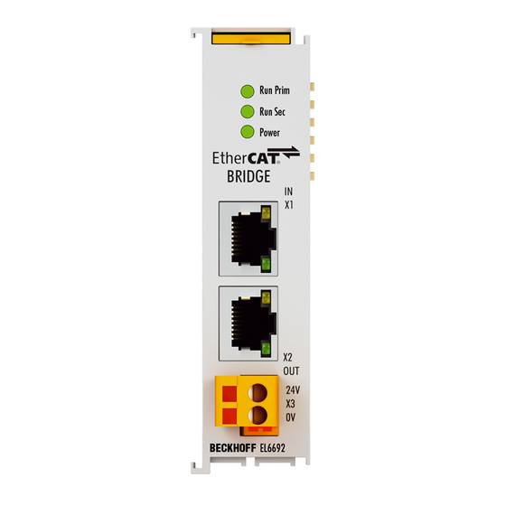
Product overview Product overview Introduction Fig. 10: EL6692 EtherCAT bridge terminal with distributed clocks support The EtherCAT bridge terminal enables data exchange between EtherCAT strands and different masters. It also enables synchronization of the distributed clocks of the individual strands. The power supply on the primary side (E-Bus) comes from the E-Bus, on the secondary side (RJ 45) via an external connection. -
Page 15: Technical Data
Product overview Technical data Technical data EL6692 Connection technology Primary side: E-bus Secondary side: RJ45 Width in the process image max. 480 bytes in each direction Data transport time from one EtherCAT side to the typical 1..4 ms opposite side... -
Page 16: Internal And External Ethercat Synchronization
• 1 ns time resolution corresponds to 1 digit, scope of 64 bits corresponds to approx. 584 years • The EtherCAT master must keep the distributed clocks synchronous within the system accuracy (EtherCAT: <100 ns) using synchronization datagrams. Version: 3.2 EL6692... -
Page 17: Fig. 12 Mapping Of Dc To The Topology
• In the event of topology changes the EtherCAT master must re-synchronize the clocks accordingly. • Not all EtherCAT masters support this procedure. • The EtherCAT master in the Beckhoff TwinCAT automation suite fully supports distributed clocks. Slave: • Due to the high precision required this local clock is implemented in hardware (ASIC, FPGA). -
Page 18: Fig. 13 Ethercat Topology With External Reference Clock
The maximum offset adjustment is ±½ cycle time. External EtherCAT synchronization External synchronization sources (e.g. EL6688, EL6692) can only be used from TwinCAT 2.11 used. In older versions of TwinCAT such EtherCAT slaves have no meaningful function. -
Page 19: Fig. 14 Twincat 2.11 Distributed Clock Settings - Sample For El6688 In Ptp Slave Mode As Time Ref- Erence For The Local Ethercat System
• If local DC time values in the synchronized EtherCAT system are to be related to the absolute reference from the higher-level EtherCAT system (e.g. from EL1252 timestamp terminals), the user must adjust this offset with each local timestamp. EL6692 Version: 3.2... -
Page 20: Start
EL1252 timestamp channel 1, local DC time ExtToDcOffset Fig. 15: display current offsets Fig. 16: Current offsets Start For commissioning: • Install the EL6692 as described in chapter Installation and wiring [} 32]. • Configure the EL6692 in TwinCAT as described in the chapter Commissioning [} 43]. Version: 3.2 EL6692... -
Page 21: Basics Communication
EtherCAT devices from Beckhoff. Recommended cables Suitable cables for the connection of EtherCAT devices can be found on the Beckhoff website! E-Bus supply A bus coupler can supply the EL terminals added to it with the E-bus system voltage of 5 V; a coupler is thereby loadable up to 2 A as a rule (see details in respective device documentation). -
Page 22: General Notes For Setting The Watchdog
The PDI watchdog can be used to monitor this communication for failure. The PDI watchdog monitors correct and timely process data communication with the ESC from the application side. The settings of the SM- and PDI-watchdog must be done for each slave separately in the TwinCAT System Manager. Version: 3.2 EL6692... -
Page 23: Fig. 18 Ethercat Tab -> Advanced Settings -> Behavior -> Watchdog
The standard setting of 1000 for the SM watchdog corresponds to a release time of 100 ms. The value in multiplier + 2 corresponds to the number of basic 40 ns ticks representing a watchdog tick. The multiplier can be modified in order to adjust the watchdog time over a larger range. EL6692 Version: 3.2... -
Page 24: Ethercat State Machine
EtherCAT master to the device in each state, particularly during the bootup of the slave. A distinction is made between the following states: • Init • Pre-Operational • Safe-Operational and • Operational • Boot The regular state of each EtherCAT slave after bootup is the OP state. Version: 3.2 EL6692... -
Page 25: Fig. 19 States Of The Ethercat State Machine
Before the EtherCAT master switches the EtherCAT slave from Safe-Op to Op it must transfer valid output data. In the Op state the slave copies the output data of the masters to its outputs. Process data and mailbox communication is possible. EL6692 Version: 3.2... -
Page 26: Coe Interface
Not every EtherCAT device must have a CoE list. Simple I/O modules without dedicated processor usually have no variable parameters and therefore no CoE list. If a device has a CoE list, it is shown in the TwinCAT System Manager as a separate tab with a listing of the elements: Version: 3.2 EL6692... -
Page 27: Fig. 20 "Coe Online " Tab
Data management If slave CoE parameters are modified online, Beckhoff devices store any changes in a fail-safe manner in the EEPROM, i.e. the modified CoE parameters are still available after a restart. The situation may be different with other manufacturers. -
Page 28: Fig. 21 Startup List In The Twincat System Manager
Changes in the local CoE list of the terminal are lost if the terminal is replaced. If a terminal is re- placed with a new Beckhoff terminal, it will have the default settings. It is therefore advisable to link all changes in the CoE list of an EtherCAT slave with the Startup list of the slave, which is pro- cessed whenever the EtherCAT fieldbus is started. -
Page 29: Fig. 22 Offline List
◦ The actual current slave list is read. This may take several seconds, depending on the size and cycle time. ◦ The actual identity is displayed ◦ The firmware and hardware version of the equipment according to the electronic information is displayed ◦ Online is shown in green. Fig. 23: Online list EL6692 Version: 3.2... - Page 30 • Channel 1: parameter range 0x8010:00 ... 0x801F:255 • Channel 2: parameter range 0x8020:00 ... 0x802F:255 • ... This is generally written as 0x80n0. Detailed information on the CoE interface can be found in the EtherCAT system documentation on the Beckhoff website. Version: 3.2 EL6692...
-
Page 31: Distributed Clock
4.2 seconds) • The EtherCAT master automatically synchronizes the local clock with the master clock in the EtherCAT bus with a precision of < 100 ns. For detailed information please refer to the EtherCAT system description. EL6692 Version: 3.2... -
Page 32: Mounting And Wiring
Terminal Modules und EtherCAT Modules of KMxxxx and EMxxxx series, same as the terminals of the EL66xx and EL67xx series does not fit to the DIN Rail TH 35-15 with 2,2 to 2,5 mm material thickness (according to EN 60715)! Version: 3.2 EL6692... -
Page 33: Mounting And Demounting - Terminals With Traction Lever Unlocking
• Lever the unlatching hook on the left-hand side of the terminal module upwards with a screwdriver (3). As you do this ◦ an internal mechanism pulls the two latching lugs (3a) from the top hat rail back into the terminal module, ◦ the unlatching hook moves forwards (3b) and engages EL6692 Version: 3.2... -
Page 34: Mounting And Demounting - Terminals With Front Unlocking
• Pull (4) the terminal module away from the mounting surface. Mounting and demounting - terminals with front unlocking The terminal modules are fastened to the assembly surface with the aid of a 35 mm mounting rail (e.g. mounting rail TH 35-15). Version: 3.2 EL6692... - Page 35 • Attach the cables. Demounting • Remove all the cables. • Lever the unlatching hook back with thumb and forefinger (3). An internal mechanism pulls the two latching lugs (3a) from the top hat rail back into the terminal module. EL6692 Version: 3.2...
-
Page 36: Positioning Of Passive Terminals
The passive terminals have no current consump- tion out of the E-Bus. To ensure an optimal data transfer, you must not directly string together more than 2 passive termi- nals! Examples for positioning of passive terminals (highlighted) Fig. 24: Correct positioning Version: 3.2 EL6692... -
Page 37: Installation Positions
EL/KL terminals to face forward (see Fig. “Recommended distances for standard installation position”). The terminals are ventilated from below, which enables optimum cooling of the electronics through convection. "From below" is relative to the acceleration of gravity. EL6692 Version: 3.2... -
Page 38: Fig. 26 Recommended Distances For Standard Installation Position
Other installation positions All other installation positions are characterized by different spatial arrangement of the mounting rail - see Fig “Other installation positions”. The minimum distances to ambient specified above also apply to these installation positions. Version: 3.2 EL6692... -
Page 39: Atex - Special Conditions (Standard Temperature Range)
80°C at the wire branching points, then cables must be selected whose tempera- ture data correspond to the actual measured temperature values! • Observe the permissible ambient temperature range of 0 to 55°C for the use of Beckhoff fieldbus compo- nents standard temperature range in potentially explosive areas! •... - Page 40 Mounting and wiring II 3G KEMA 10ATEX0075 X Ex nA IIC T4 Gc Ta: 0 … +55°C II 3G KEMA 10ATEX0075 X Ex nC IIC T4 Gc Ta: 0 … +55°C Version: 3.2 EL6692...
-
Page 41: Leds And Connection
Mounting and wiring LEDs and connection Fig. 28: EL6692 LEDs LEDs Color Meaning RUN PRIM green LED for indicating the operating state of the primary EtherCAT strand (terminal): State of the EtherCAT State Machine [} 92]: INIT = initialization of the terminal flashing State of the EtherCAT State Machine: PREOP = function for mailbox communication and dif-... -
Page 42: Fig. 29 Connection El6695
Terminal point Description EtherCAT Input (RJ45 with 10BASE-T/100BASE-TX Ethernet) EtherCAT output (RJ45 with 10BASE-T/100BASE-TX Ethernet) 2-pole socket terminal connection (24 VDC), secondary side power supply Diagnostic LEDs For the LED description please refer to the chapter Diagnostic LEDs Version: 3.2 EL6692... -
Page 43: Commissioning
• "offline": The configuration can be customized by adding and positioning individual components. These can be selected from a directory and configured. ◦ The procedure for offline mode can be found under http://infosys.beckhoff.com: TwinCAT 2 → TwinCAT System Manager → IO - Configuration → Adding an I/O Device •... -
Page 44: Fig. 30 Relationship Between User Side (Commissioning) And Installation
• Linked via the X001 port (RJ-45): EK1100 EtherCAT Coupler • Connected to the EK1100 EtherCAT coupler on the right (E-bus): EL2008 (8-channel digital output terminal 24 V DC; 0.5 A) • (Optional via X000: a link to an external PC for the user interface) Version: 3.2 EL6692... -
Page 45: Fig. 31 Control Configuration With Embedded Pc, Input (El1004) And Output (El2008)
Note that all combinations of a configuration are possible; for example, the EL1004 terminal could also be connected after the coupler, or the EL2008 terminal could additionally be connected to the CX2040 on the right, in which case the EK1100 coupler wouldn’t be necessary. EL6692 Version: 3.2... -
Page 46: Fig. 32 Initial Twincat 2 User Interface
If the intention is to address the TwinCAT runtime environment installed on a PLC as development environment remotely from another system, the target system must be made known first. In the menu under "Actions" → "Choose Target System...", via the symbol " " or the "F8" key, open the following window: Version: 3.2 EL6692... -
Page 47: Fig. 33 Selection Of The Target System
Fig. 34: Specify the PLC for access by the TwinCAT System Manager: selection of the target system Once the target system has been entered, it is available for selection as follows (a password may have to be entered): After confirmation with "OK" the target system can be accessed via the System Manager. EL6692 Version: 3.2... -
Page 48: Fig. 35 Select "Scan Devices
Confirm the message "Find new boxes", in order to determine the terminals connected to the devices. "Free Run" enables manipulation of input and output values in "Config mode" and should also be acknowledged. Based on the sample configuration [} 44] described at the beginning of this section, the result is as follows: Version: 3.2 EL6692... -
Page 49: Fig. 37 Mapping Of The Configuration In The Twincat 2 System Manager
TwinCAT PLC Control is the development environment for the creation of the controller in different program environments: TwinCAT PLC Control supports all languages described in IEC 61131-3. There are two text- based languages and three graphical languages. • Text-based languages ◦ Instruction List (IL) EL6692 Version: 3.2... -
Page 50: Fig. 39 Twincat Plc Control After Startup
The following section refers to Structured Text (ST). After starting TwinCAT PLC Control, the following user interface is shown for an initial project: Fig. 39: TwinCAT PLC Control after startup Sample variables and a sample program have been created and stored under the name "PLC_example.pro": Version: 3.2 EL6692... -
Page 51: Fig. 40 Sample Program With Variables After A Compile Process (Without Variable Integration)
Manager has been notified, the warning no longer appears. First, integrate the TwinCAT PLC Control project in the System Manager via the context menu of the PLC configuration; right-click and select "Append PLC Project…": Fig. 41: Appending the TwinCAT PLC Control project EL6692 Version: 3.2... - Page 52 "PLC_example" and via "Modify Link..." "Standard": Fig. 43: Creating the links between PLC variables and process objects In the window that opens, the process object for the variable “bEL1004_Ch4” of type BOOL can be selected from the PLC configuration tree: Version: 3.2 EL6692...
- Page 53 The links can also be checked by selecting a "Goto Link Variable” from the context menu of a variable. The object opposite, in this case the PDO, is automatically selected: EL6692 Version: 3.2...
- Page 54 The PLC system can then be started as described below. Starting the controller Starting from a remote system, the PLC control has to be linked with the Embedded PC over Ethernet via "Online" → “Choose Run-Time System…": Version: 3.2 EL6692...
- Page 55 This results in the message "No program on the controller! Should the new program be loaded?", which should be acknowledged with "Yes". The runtime environment is ready for the program start: EL6692 Version: 3.2...
- Page 56 (cf. "TwinCAT System Manager" of TwinCAT 2) for communication with the electromechanical components. After successful installation of the TwinCAT system on the PC to be used for development, TwinCAT 3 (shell) displays the following user interface after startup: Version: 3.2 EL6692...
- Page 57 First create a new project via (or under "File"→“New"→ "Project…"). In the following dialog make the corresponding entries as required (as shown in the diagram): Fig. 50: Create new TwinCAT project The new project is then available in the project folder explorer: EL6692 Version: 3.2...
- Page 58 If the intention is to address the TwinCAT runtime environment installed on a PLC as development environment remotely from another system, the target system must be made known first. Via the symbol in the menu bar: expand the pull-down menu: and open the following window: Fig. 52: Selection dialog: Choose the target system Version: 3.2 EL6692...
- Page 59 The TwinCAT System Manager may first have to be set to "Config mode" via or via the menu "TwinCAT" → "Restart TwinCAT (Config mode)". Fig. 54: Select "Scan" Confirm the warning message, which follows, and select "EtherCAT" in the dialog: EL6692 Version: 3.2...
- Page 60 The whole process consists of two stages, which may be performed separately (first determine the devices, then determine the connected elements such as boxes, terminals, etc.). A scan can also be initiated by selecting "Device ..." from the context menu, which then reads the elements present in the configuration below: Version: 3.2 EL6692...
- Page 61 The following section refers to Structured Text (ST). In order to create a programming environment, a PLC subproject is added to the project sample via the context menu of "PLC" in the project folder explorer by selecting "Add New Item….": EL6692 Version: 3.2...
- Page 62 Fig. 59: Specifying the name and directory for the PLC programming environment The "Main" program, which already exists by selecting "Standard PLC project", can be opened by double- clicking on "PLC_example_project" in "POUs”. The following user interface is shown for an initial project: Version: 3.2 EL6692...
- Page 63 Commissioning Fig. 60: Initial "Main" program of the standard PLC project To continue, sample variables and a sample program have now been created: EL6692 Version: 3.2...
- Page 64 "Assignments" in the project folder explorer: Assigning variables Via the menu of an instance - variables in the "PLC” context, use the "Modify Link…" option to open a window for selecting a suitable process object (PDO) for linking: Version: 3.2 EL6692...
- Page 65 4 of the EL1004 terminal is selected for linking. In contrast, the checkbox "All types" must be ticked for creating the link for the output variables, in order to allocate a set of eight separate output bits to a byte variable. The following diagram shows the whole process: EL6692 Version: 3.2...
- Page 66 However, in this example it would then not be possible to select all output bits for the EL2008, since the terminal only makes individual digital outputs available. If a terminal has a byte, word, integer or Version: 3.2 EL6692...
- Page 67 , the "F5" key or via "PLC" in the menu selecting “Start”. The started programming environment shows the runtime values of individual variables: Fig. 67: TwinCAT development environment (VS shell): logged-in, after program startup EL6692 Version: 3.2...
-
Page 68: Twincat 2
5.2.1 Installation of the TwinCAT real-time driver In order to assign real-time capability to a standard Ethernet port of an IPC controller, the Beckhoff real-time driver has to be installed on this port under Windows. This can be done in several ways. One option is described here. - Page 69 Alternatively an EtherCAT-device can be inserted first of all as described in chapter Offline configuration creation, section “Creating the EtherCAT device” [} 79] in order to view the compatible ethernet ports via its EtherCAT properties (tab „Adapter“, button „Compatible Devices…“): EL6692 Version: 3.2...
- Page 70 After the installation the driver appears activated in the Windows overview for the network interface (Windows Start → System Properties → Network) Fig. 72: Windows properties of the network interface A correct setting of the driver could be: Version: 3.2 EL6692...
- Page 71 Commissioning Fig. 73: Exemplary correct driver setting for the Ethernet port Other possible settings have to be avoided: EL6692 Version: 3.2...
- Page 72 Commissioning Fig. 74: Incorrect driver settings for the Ethernet port Version: 3.2 EL6692...
- Page 73 DHCP. In this way the delay associated with the DHCP client for the Ethernet port assigning itself a default IP address in the absence of a DHCP server is avoided. A suitable address space is 192.168.x.x, for example. Fig. 75: TCP/IP setting for the Ethernet port EL6692 Version: 3.2...
-
Page 74: Notes Regarding Esi Device Description
The files are read (once) when a new System Manager window is opened, if they have changed since the last time the System Manager window was opened. A TwinCAT installation includes the set of Beckhoff ESI files that was current at the time when the TwinCAT build was created. - Page 75 1018 in the configuration. This is also stated by the Beckhoff compatibility rule. Refer in particular to the chapter ‘General notes on the use of Beckhoff EtherCAT IO components’ and for manual configuration to the chapter ‘Offline configuration creation’ [} 79].
- Page 76 Faulty ESI file If an ESI file is faulty and the System Manager is unable to read it, the System Manager brings up an information window. Fig. 81: Information window for faulty ESI file (left: TwinCAT 2; right: TwinCAT 3) Version: 3.2 EL6692...
- Page 77 Commissioning Reasons may include: • Structure of the *.xml does not correspond to the associated *.xsd file → check your schematics • Contents cannot be translated into a device description → contact the file manufacturer EL6692 Version: 3.2...
-
Page 78: Twincat Esi Updater
Commissioning 5.2.3 TwinCAT ESI Updater For TwinCAT 2.11 and higher, the System Manager can search for current Beckhoff ESI files automatically, if an online connection is available: Fig. 82: Using the ESI Updater (>= TwinCAT 2.11) The call up takes place under: “Options” → "Update EtherCAT Device Descriptions"... -
Page 79: Offline Configuration Creation
EL6601/EL6614 terminal select “EtherCAT Automation Protocol via EL6601”. Fig. 85: Selecting the EtherCAT connection (TwinCAT 2.11, TwinCAT 3) Then assign a real Ethernet port to this virtual device in the runtime system. Fig. 86: Selecting the Ethernet port EL6692 Version: 3.2... - Page 80 Fig. “Selection dialog for new EtherCAT device”. If the preceding device has several free ports (e.g. EK1122 or EK1100), the required port can be selected on the right-hand side (A). Overview of physical layer • “Ethernet”: cable-based 100BASE-TX: EK couplers, EP boxes, devices with RJ45/M8/M12 connector Version: 3.2 EL6692...
- Page 81 (i.e. highest) revision and therefore the latest state of production is displayed in the selection dialog for Beckhoff devices. To show all device revisions available in the system as ESI descriptions tick the “Show Hidden Devices” check box, see Fig. “Display of previous revisions”.
- Page 82 If current ESI descriptions are available in the TwinCAT system, the last revision offered in the selection dialog matches the Beckhoff state of production. It is recommended to use the last device revision when creating a new configuration, if current Beckhoff devices are used in the real application. Older revisions should only be used if older devices from stock are to be used in the application.
- Page 83 Commissioning Fig. 93: EtherCAT terminal in the TwinCAT tree (left: TwinCAT 2; right: TwinCAT 3) EL6692 Version: 3.2...
-
Page 84: Online Configuration Creation
This scan mode attempts to find not only EtherCAT devices (or Ethernet ports that are usable as such), but also NOVRAM, fieldbus cards, SMB etc. However, not all devices can be found automatically. Fig. 96: Note for automatic device scan (left: TwinCAT 2; right: TwinCAT 3) Version: 3.2 EL6692... - Page 85 [} 89] with the defined initial configuration.Background: since Beckhoff occasionally increases the revision version of the delivered products for product maintenance reasons, a configuration can be created by such a scan which (with an identical machine construction) is identical according to the device list;...
- Page 86 Likewise, A might create spare parts stores worldwide for the coming series-produced machines with EL2521-0025-1018 terminals. After some time Beckhoff extends the EL2521-0025 by a new feature C. Therefore the FW is changed, outwardly recognizable by a higher FW version and a new revision -1019. Nevertheless the new device naturally supports functions and interfaces of the predecessor version(s);...
- Page 87 Fig. 105: Displaying of “Free Run” and “Config Mode” toggling right below in the status bar Fig. 106: TwinCAT can also be switched to this state by using a button (left: TwinCAT 2; right: TwinCAT 3) The EtherCAT system should then be in a functional cyclic state, as shown in Fig. “Online display example”. EL6692 Version: 3.2...
- Page 88 The connections and devices should be checked in a targeted manner, e.g. via the emergency scan. Then re-run the scan. Fig. 108: Faulty identification In the System Manager such devices may be set up as EK0000 or unknown devices. Operation is not possible or meaningful. Version: 3.2 EL6692...
- Page 89 A ‘ChangeTo’ or ‘Copy’ should only be carried out with care, taking into consideration the Beckhoff IO compatibility rule (see above). The device configuration is then replaced by the revision found; this can affect the supported process data and functions.
- Page 90 If current ESI descriptions are available in the TwinCAT system, the last revision offered in the selection dialog matches the Beckhoff state of production. It is recommended to use the last device revision when creating a new configuration, if current Beckhoff devices are used in the real application. Older revisions should only be used if older devices from stock are to be used in the application.
- Page 91 This function is preferably to be used on AX5000 devices. Change to Alternative Type The TwinCAT System Manager offers a function for the exchange of a device: Change to Alternative Type Fig. 114: TwinCAT 2 Dialog Change to Alternative Type EL6692 Version: 3.2...
-
Page 92: Ethercat Subscriber Configuration
Comment Here you can add a comment (e.g. regarding the system). Disabled Here you can deactivate the EtherCAT device. Create symbols Access to this EtherCAT slave via ADS is only available if this control box is activated. Version: 3.2 EL6692... - Page 93 CANopen process data objects (Process Data Objects, PDOs). The user can select a PDO via PDO assignment and modify the content of the individual PDO via this dialog, if the EtherCAT slave supports this function. EL6692 Version: 3.2...
- Page 94 For Beckhoff EtherCAT EL, ES, EM, EJ and EP slaves the following applies in general: • The input/output process data supported by the device are defined by the manufacturer in the ESI/XML description.
- Page 95 (CoE) or Servo drive over EtherCAT protocol. This tab indicates which download requests are sent to the mailbox during startup. It is also possible to add new mailbox requests to the list display. The download requests are sent to the slave in the same order as they are shown in the list. EL6692 Version: 3.2...
- Page 96 (CoE) protocol. This dialog lists the content of the object list of the slave (SDO upload) and enables the user to modify the content of an object from this list. Details for the objects of the individual EtherCAT devices can be found in the device-specific object descriptions. Version: 3.2 EL6692...
- Page 97 The Update list button updates all objects in the displayed list Auto Update If this check box is selected, the content of the objects is updated automatically. Advanced The Advanced button opens the Advanced Settings dialog. Here you can specify which objects are displayed in the list. EL6692 Version: 3.2...
- Page 98 Offline - via EDS File If this option button is selected, the list of the objects included in the object list is read from an EDS file provided by the user. „Online“ tab Fig. 123: „Online“ tab Version: 3.2 EL6692...
- Page 99 Fig. 124: "DC" tab (Distributed Clocks) Operation Mode Options (optional): • FreeRun • SM-Synchron • DC-Synchron (Input based) • DC-Synchron Advanced Settings… Advanced settings for readjustment of the real time determinant TwinCAT- clock Detailed information to Distributed Clocks are specified on http://infosys.beckhoff.com: EL6692 Version: 3.2...
- Page 100 Sync Manager! Consequently, this PDO cannot be deleted from the PDO Assignment list Sync Manager to which this PDO is assigned. If this entry is empty, this PDO does not take part in the process data traffic. Sync unit to which this PDO is assigned. Version: 3.2 EL6692...
-
Page 101: General Notes - Ethercat Slave Application
EtherCAT and the TwinCAT System Manager offer comprehensive diagnostic elements of this kind. Those diagnostic elements that are helpful to the controlling task for diagnosis that is accurate for the current cycle when in operation (not during commissioning) are discussed below. EL6692 Version: 3.2... - Page 102 Fig. “Basic EtherCAT Slave Diagnosis in the PLC” shows an example of an implementation of basic EtherCAT Slave Diagnosis. A Beckhoff EL3102 (2-channel analogue input terminal) is used here, as it offers both the communication diagnosis typical of a slave and the functional diagnosis that is specific to a channel.
- Page 103 Commissioning Fig. 126: Basic EtherCAT Slave Diagnosis in the PLC The following aspects are covered here: EL6692 Version: 3.2...
- Page 104 The CoE parameter directory (CanOpen-over-EtherCAT) is used to manage the set values for the slave concerned. Changes may, in some circumstances, have to be made here when commissioning a relatively complex EtherCAT Slave. It can be accessed through the TwinCAT System Manager, see Fig. “EL3102, CoE directory”: Version: 3.2 EL6692...
- Page 105 Commissioning interfaces are being introduced as part of an ongoing process for EL/EP EtherCAT devices. These are available in TwinCAT System Managers from TwinCAT 2.11R2 and above. They are integrated into the System Manager through appropriately extended ESI configuration files. EL6692 Version: 3.2...
- Page 106 The target state wanted by the user, and which is brought about automatically at start-up by TwinCAT, can be set in the System Manager. As soon as TwinCAT reaches the status RUN, the TwinCAT EtherCAT Master will approach the target states. Version: 3.2 EL6692...
- Page 107 Fig. 129: Default behaviour of the System Manager In addition, the target state of any particular Slave can be set in the "Advanced Settings" dialogue; the standard setting is again OP. Fig. 130: Default target state in the Slave EL6692 Version: 3.2...
- Page 108 The pre-calculated theoretical maximum E-Bus current is displayed in the TwinCAT System Manager as a column value. A shortfall is marked by a negative total amount and an exclamation mark; a power feed terminal is to be placed before such a position. Version: 3.2 EL6692...
- Page 109 Fig. 133: Warning message for exceeding E-Bus current NOTE Caution! Malfunction possible! The same ground potential must be used for the E-Bus supply of all EtherCAT terminals in a terminal block! EL6692 Version: 3.2...
-
Page 110: Basic Principles Of Function And Commissioning
If distributed clocks are used in both EtherCAT circuits the EL6692 can also be used for synchronizing the two timebases. In this case the user has to define which side has the reference clock with the higher priority. - Page 111 Inputs" or "IO Outputs" opens the dialog box from the fig. Appending process data variables. Fig. 135: Appending process data variables In the full configuration with activated PDO 0x1A02, the EL6692 provides the diagnostic process data from the fig. Full range of diagnostic process data Fig. 136: Full range of diagnostic process data...
- Page 112 • TxPDO toggle: Bit toggles when a new set of process data has been delivered by the opposite side, but has not yet been collected by the receiving side. In this way the EL6692 also enables operation with EtherCAT cycle times that are greater than the transport time.
- Page 113 Fig. 139: Device Reload The error message "Invalid SM In cfg" or "Invalid SM Out cfg" appears in the logger window. The secondary side can be read, if both EtherCAT sides of the EL6692 are at least in PRE-OP state. EL6692...
- Page 114 Fig. 141: "Get configuration" on the secondary side The CoE folders of both halves of the EL6692 are used to save the process data configuration in the EL6692. The types and complexity of the definable process data are therefore limited. If the notes from the fig.
- Page 115 Fig. 143: Warning message for complex data types Application notes Process data The following must be observed in relation to the EL6692 process data: • Data quantity a maximum of 480 bytes can be transmitted in each direction. • Number of variables no more than 59 variables should be configured per side (primary/secondary) and data direction (input/ output).
- Page 116 For an automatic restart of the secondary bridge side, function blocks from the TcEtherCAT.lib should be used in the secondary-side PLC in this case. The default settings of the system manager "ReInit after ComError" and "Auto Restore States" are insufficient in this case. The LED RUN SEC responds accordingly. Version: 3.2 EL6692...
- Page 117 Transporting the configured process data from one EtherCAT side to the other takes a certain amount of time, depending on the number of bytes. The data transfer is free-running and therefore not synchronized with one of the two EtherCAT sides. As a typical sample, measurement of an EL6692 with FW01 shows the following values: Fig. 149: Typical throughput time measurement for a EL6692 (FW01) - Beckhoff reserves the right to...
- Page 118 Select "All Types" to make Var109 available for selection. Otherwise only exactly matching 2 bit process data would be displayed. Now a dialog box opens for the specification of the offset; see the fig. Offset specification. Confirm the suggestion. Version: 3.2 EL6692...
- Page 119 Fig. 152: Offset specification Extent of process data The EL6692 can transport a maximum of 480 bytes in each direction. In each transport direction the data may consist of a single large process data such as a structure or an array.
-
Page 120: Extended Functions
Information System. AoE is a VoE (vendor-specific protocol over EtherCAT). The EL6692 can transport ADS telegrams to the other side directly (AoE), i.e. without underlying IP channel. To this end the EL6692 must be entered in the System Manager as an ADS gateway; see the following sample (https://infosys.beckhoff.com/content/1033/el6692/Resources/zip/2460148491.zip) Two PCs with TwinCAT 2.10, b1340 and an EL6692 with Firmware 05 are used. - Page 121 Commissioning Fig. 155: Entering the EL6692 as an ADS gateway If an EL6692 (A) exists, the NetId of the EL6692 (D) can be changed (E) under RouteSettings (B), NetIdManagement (C). Fig. 156: New NetId entered After activating the configuration and restarting TwinCAT, the ADS router is now instructed to send queries to the ADS device 192.168.2.1.1.1 via the AoE interface of the EL6692.
-
Page 122: External Twincat Synchronization
In this example, two Beckhoff IPCs with TwinCAT 2.11, b1539, will be synchronized with each other. One PC is the master clock, the second (slave clock) synchronizes its ‘time’ to the first. As the fieldbus, EtherCAT makes the necessary operating resources available, in particular EtherCAT’s own synchronization... - Page 123 In this example, the EL6692 is synchronized in the direction PrimarySide --> SecondarySide (RJ45 connection). Synchronization in the other direction is also possible. EL6692 documentation Please note the information in the EL6692 documentation regarding the system behavior of this ter- minal. Demo program In this demo program, the slave’s own local DC time from the ReferenceClock in the EtherCAT strand is...
- Page 124 Commissioning Sync Master side Fig. 159: Device on the master side Fig. 160: Set the EL6692 PrimarySide to DC Fig. 161: Activate PDO 0x1A02 to display the time stamps Timestamp PDO The activation of the timestamp PDO indicates to the TwinCAT software on the respective side that this side is to be synchronized, i.e.
- Page 125 Fig. 162: Set the synchronization direction on the PrimarySide; in this case SyncSettings: Primary -> Secondary Fig. 163: Activate the display of the DC offsets in the EtherCAT master; can be evaluated on the master side Fig. 164: Master PC works with its own ReferenceClock as a basis EL6692 Version: 3.2...
- Page 126 Fig. 165: SecondarySide of the EL6692 Fig. 166: EtherCAT master settings, slave side After the restart, the DC function of the EL6692 is known to the EtherCAT master; therefore, it now offers this EL6692 as an ExternalSyncDevice in the DC dialogue. The linking of the following variables is necessary for the evaluations; see the fig. Slave side.
- Page 127 See also the note [} 122]. On the slave side, the start of the synchronization can be observed with the incorporated visualization. Fig. 168: Start slave side Only the local DC time is available on the slave side immediately after the start. EL6692 Version: 3.2...
- Page 128 Fig. 169: Time stamp known Following receipt of the first time stamps via the EL6692, the offset is known; in this case it is around 3 minutes different to the time of the IPC used. Synchronization has begun; in this sample a window of ± 10 µs is to be achieved.
-
Page 129: Object Description And Parameterization
EtherCAT XML Device Description The display matches that of the CoE objects from the EtherCAT XML Device Description. We rec- ommend downloading the latest XML file from the download area of the Beckhoff website and in- stalling it according to installation instructions. -
Page 130: Objects For Regular Operation
Additional System Additional DC time for calculating the control value UINT64 0x000000000 Time 0000000 5.7.2 Objects for regular operation The EL6692 has no such objects. 5.7.3 Input data Index 6000 Input Data Index (hex) Name Meaning Data type Flags Default... -
Page 131: Standard Objects (0X1000-0X1Fff)
Index (hex) Name Meaning Data type Flags Default 1008:0 Device name Device name of the EtherCAT slave STRING EL6692-0000 Index 1009 Hardware version Index (hex) Name Meaning Data type Flags Default 1009:0 Hardware version Hardware version of the EtherCAT slave... - Page 132 7. PDO Mapping entry (object 0x10F4 (External synchro- UINT32 0x10F4:0F, 1 nization status), entry 0x0F (Time stamp update toggle)) 1A01:08 SubIndex 008 8. PDO Mapping entry (object 0x10F4 (External synchro- UINT32 0x10F4:10, 1 nization status), entry 0x10 (External device not con- nected)) Version: 3.2 EL6692...
- Page 133 Sync-Manager Type Channel 2: Mailbox Read UINT8 0x02 (2 1C00:03 SubIndex 003 Sync-Manager Type Channel 3: Process Data Write UINT8 0x03 (3 (Outputs) 1C00:04 SubIndex 004 Sync-Manager Type Channel 4: Process Data Read (In- UINT8 0x04 (4 puts) EL6692 Version: 3.2...
- Page 134 Shift too short counter Number of occasions that the interval between SYNC0 UINT16 0x0000 (0 and SYNC1 event was too short (DC mode only) 1C32:20 Sync error The synchronization was not correct in the last cycle BOOLEAN 0x00 (0 (outputs were output too late; DC mode only) Version: 3.2 EL6692...
- Page 135 UINT16 0x0000 (0 as 0x1C32:11 [} 134] counter 1C33:0C Cycle exceeded UINT16 0x0000 (0 as 0x1C32:12 [} 134] counter 1C33:0D Shift too short counter as 0x1C32:13 [} 134] UINT16 0x0000 (0 1C33:20 Sync error BOOLEAN 0x00 (0 as 0x1C32:32 [} 134] EL6692 Version: 3.2...
-
Page 136: Appendix
Beckhoff EtherCAT modules are intended for use with Beckhoff’s UL Listed EtherCAT Sys- tem only. Examination For cULus examination, the Beckhoff I/O System has only been investigated for risk of fire and electrical shock (in accordance with UL508 and CSA C22.2 No. 142). For devices with Ethernet connectors Not for connection to telecommunication circuits. -
Page 137: Atex Documentation
Note • It is recommended to use the newest possible firmware for the respective hardware • Beckhoff is not under any obligation to provide customers with free firmware updates for delivered products. NOTE Risk of damage to the device! Pay attention to the instructions for firmware updates on the separate page [} 138]. -
Page 138: Firmware Update El/Es/Em/Elm/Epxxxx
Check on the Beckhoff web page whether more up-to-date documentation is available. Firmware Update EL/ES/EM/ELM/EPxxxx This section describes the device update for Beckhoff EtherCAT slaves from the EL/ES, ELM, EM, EK and EP series. A firmware update should only be carried out after consultation with Beckhoff support. -
Page 139: Device Description Esi File/Xml
(in this case EL3204). Normally the configured revision must be the same or lower than that actually present in the terminal network. For further information on this, please refer to the EtherCAT system documentation. EL6692 Version: 3.2... - Page 140 The device revision is closely linked to the firmware and hardware used. Incompatible combinations lead to malfunctions or even final shutdown of the device. Corresponding updates should only be carried out in consultation with Beckhoff support. Display of ESI slave identifier...
- Page 141 • Right-clicking on the slave in the online display opens the EEPROM Update dialog, Fig. EEPROM Update Fig. 175: EEPROM Update The new ESI description is selected in the following dialog, see Fig. Selecting the new ESI. The checkbox Show Hidden Devices also displays older, normally hidden versions of a slave. EL6692 Version: 3.2...
-
Page 142: Firmware Explanation
• offline: The EtherCAT Slave Information ESI/XML may contain the default content of the CoE. This CoE directory can only be displayed if it is included in the ESI (e.g. "Beckhoff EL5xxx.xml"). The Advanced button must be used for switching between the two views. -
Page 143: Updating Controller Firmware *.Efw
The Online CoE directory is managed by the controller and stored in a dedicated EEPROM, which is generally not changed during a firmware update. Switch to the Online tab to update the controller firmware of a slave, see Fig. Firmware Update. EL6692 Version: 3.2... - Page 144 Appendix Fig. 178: Firmware Update Proceed as follows, unless instructed otherwise by Beckhoff support. Valid for TwinCAT 2 and 3 as EtherCAT master. • Switch TwinCAT system to ConfigMode/FreeRun with cycle time >= 1 ms (default in ConfigMode is 4 ms). A FW-Update during real time operation is not recommended.
-
Page 145: Fpga Firmware *.Rbf
The TwinCAT System Manager indicates the FPGA firmware version. Click on the Ethernet card of your EtherCAT strand (Device 2 in the example) and select the Online tab. The Reg:0002 column indicates the firmware version of the individual EtherCAT devices in hexadecimal and decimal representation. EL6692 Version: 3.2... - Page 146 Fig. 180: Context menu Properties The Advanced Settings dialog appears where the columns to be displayed can be selected. Under Diagnosis/Online View select the '0002 ETxxxx Build' check box in order to activate the FPGA firmware version display. Version: 3.2 EL6692...
- Page 147 Older firmware versions can only be updated by the manufacturer! Updating an EtherCAT device The following sequence order have to be met if no other specifications are given (e.g. by the Beckhoff support): • Switch TwinCAT system to ConfigMode/FreeRun with cycle time >= 1 ms (default in ConfigMode is 4 ms).
- Page 148 • In the TwinCAT System Manager select the terminal for which the FPGA firmware is to be updated (in the example: Terminal 5: EL5001) and click the Advanced Settings button in the EtherCAT tab: • The Advanced Settings dialog appears. Under ESC Access/E²PROM/FPGA click on Write FPGA button: Version: 3.2 EL6692...
-
Page 149: Simultaneous Updating Of Several Ethercat Devices
The firmware and ESI descriptions of several devices can be updated simultaneously, provided the devices have the same firmware file/ESI. Fig. 182: Multiple selection and firmware update Select the required slaves and carry out the firmware update in BOOTSTRAP mode as described above. EL6692 Version: 3.2... -
Page 150: Restoring The Delivery State
Fig. 184: Entering a restore value in the Set Value dialog Alternative restore value In some older terminals the backup objects can be switched with an alternative restore value: Deci- mal value: 1819238756, Hexadecimal value: 0x6C6F6164An incorrect entry for the restore value has no effect. Version: 3.2 EL6692... -
Page 151: Support And Service
Beckhoff's branch offices and representatives Please contact your Beckhoff branch office or representative for local support and service on Beckhoff products! The addresses of Beckhoff's branch offices and representatives round the world can be found on her internet pages: http://www.beckhoff.com You will also find further documentation for Beckhoff components there. - Page 152 ELM3604-0002 terminal with unique ID number (QR code) 100001051 and serial/ batch num- ber 44160201..........................Fig. 9 BIC as data matrix code (DMC, code scheme ECC200)............. Fig. 10 EL6692 ............................Fig. 11 Simple I/O topology ........................Fig. 12 mapping of DC to the topology ....................
- Page 153 Using the ESI Updater (>= TwinCAT 2.11).................. Fig. 83 Using the ESI Updater (TwinCAT 3).................... Fig. 84 Append EtherCAT device (left: TwinCAT 2; right: TwinCAT 3) ........... Fig. 85 Selecting the EtherCAT connection (TwinCAT 2.11, TwinCAT 3)..........Fig. 86 Selecting the Ethernet port ......................EL6692 Version: 3.2...
- Page 154 Fig. 127 EL3102, CoE directory ........................ 105 Fig. 128 Example of commissioning aid for a EL3204 ................106 Fig. 129 Default behaviour of the System Manager .................. 107 Fig. 130 Default target state in the Slave ....................107 Version: 3.2 EL6692...
- Page 155 Fig. 147 Deactivate PDO configuration download ..................116 Fig. 148 Mode switching ..........................117 Fig. 149 Typical throughput time measurement for a EL6692 (FW01) - Beckhoff reserves the right to modifications without notification....................117 Fig. 150 Byte process data definition......................117 Fig.
- Page 156 Fig. 181 Dialog Advanced Settings ......................147 Fig. 182 Multiple selection and firmware update ..................149 Fig. 183 Selecting the "Restore default parameters" PDO ................ 150 Fig. 184 Entering a restore value in the Set Value dialog................150 Version: 3.2 EL6692...
Need help?
Do you have a question about the EL6692 and is the answer not in the manual?
Questions and answers