
Related Manuals for Beckhoff EL3101


Summary of Contents for Beckhoff EL3101
- Page 1 Documentation EL31xx-00xx Analog Input Terminals (16 Bit) Version: Date: 2018-08-28...
-
Page 3: Table Of Contents
Table of contents Table of contents 1 Foreword .............................. 7 Product overview Analog Input Terminals .................. 7 Notes on the documentation...................... 8 Safety instructions .......................... 9 Documentation issue status ...................... 10 Version identification of EtherCAT devices .................. 11 2 Product overview............................. 16 EL310x ............................ 16 2.1.1 EL310x - Introduction....................... 16 2.1.2 EL310x - Technical data .................... - Page 4 Table of contents Positioning of passive Terminals ..................... 53 ATEX - Special conditions (standard temperature range) ............... 54 ATEX - Special conditions (extended temperature range) .............. 55 ATEX Documentation ........................ 56 4.10 UL notice ............................ 56 4.11 LEDs and connection ........................ 58 4.11.1 EL310x - LEDs and connection .................. 58 4.11.2 EL311x - LEDs and connection ..................
- Page 5 Table of contents 5.7.3 TwinSAFE SC process data EL31x4-0090.............. 191 CoE object description and parameterization ................ 191 5.8.1 Restore object........................ 192 5.8.2 Configuration data ...................... 192 5.8.3 Input data........................ 196 5.8.4 Output data ........................ 197 5.8.5 Standard objects...................... 197 5.8.6 Objects TwinSAFE Single Channel (EL31x4-0090) ............ 203 Error messages and diagnosis ...................... 204 6 Appendix .............................. 206 EtherCAT AL Status Codes ...................... 206...
- Page 6 Table of contents Version: 5.9 EL31xx-00xx...
-
Page 7: Foreword
Foreword Foreword Product overview Analog Input Terminals EL3101, EL3102, EL3104 [} 16] 1, 2 and 4 channel, -10 V to +10 V, differential input EL3111, EL3112, EL3114 [} 18] 1, 2 and 4 channel, 0 mA to 20 mA, differential input EL3112-0011 [} 18] 2 channel, -20 mA to 20 mA, differential input EL3121, EL3122, EL3124 [} 20]... -
Page 8: Notes On The Documentation
The TwinCAT Technology is covered, including but not limited to the following patent applications and patents: EP0851348, US6167425 with corresponding applications or registrations in various other countries. ® EtherCAT is registered trademark and patented technology, licensed by Beckhoff Automation GmbH, Germany Copyright © Beckhoff Automation GmbH & Co. KG, Germany. -
Page 9: Safety Instructions
All the components are supplied in particular hardware and software configurations appropriate for the application. Modifications to hardware or software configurations other than those described in the documentation are not permitted, and nullify the liability of Beckhoff Automation GmbH & Co. KG. Personnel qualification This description is only intended for trained specialists in control, automation and drive engineering who are familiar with the applicable national standards. -
Page 10: Documentation Issue Status
Foreword Documentation issue status Version Comment • Update chapter "Process data and operation modes” • Update revision status • Addenda EL3174-0090 • Update chapter "Commissioning” • Addenda EL3124-0090 • Addenda EL3174-0032 • Update chapter "Technical data" • Update chapter "Commissioning” •... -
Page 11: Version Identification Of Ethercat Devices
• EL3142-0010 description amended, technical data corrected • Description of filter settings amended (object description) • Provisional documentation for EL31x2 Version identification of EtherCAT devices Designation A Beckhoff EtherCAT device has a 14-digit designation, made up of • family key • type • version • revision... - Page 12 Production lot/batch number/serial number/date code/D number The serial number for Beckhoff IO devices is usually the 8-digit number printed on the device or on a sticker. The serial number indicates the configuration in delivery state and therefore refers to a whole production batch, without distinguishing the individual modules of a batch.
-
Page 13: Fig. 1 El5021 El Terminal, Standard Ip20 Io Device With Serial/ Batch Number And Revision Id (Since 2014/01)
Foreword Examples of markings Fig. 1: EL5021 EL terminal, standard IP20 IO device with serial/ batch number and revision ID (since 2014/01) Fig. 2: EK1100 EtherCAT coupler, standard IP20 IO device with serial/ batch number Fig. 3: CU2016 switch with serial/ batch number EL31xx-00xx Version: 5.9... -
Page 14: Fig. 4 El3202-0020 With Serial/ Batch Number 26131006 And Unique Id-Number 204418
Foreword Fig. 4: EL3202-0020 with serial/ batch number 26131006 and unique ID-number 204418 Fig. 5: EP1258-00001 IP67 EtherCAT Box with batch number/ date code 22090101 and unique serial number 158102 Fig. 6: EP1908-0002 IP67 EtherCAT Safety Box with batch number/ date code 071201FF and unique serial number 00346070 Fig. 7: EL2904 IP20 safety terminal with batch number/ date code 50110302 and unique serial number 00331701... -
Page 15: Fig. 8 Elm3604-0002 Terminal With Unique Id Number (Qr Code) 100001051 And Serial/ Batch Num- Ber 44160201
Foreword Fig. 8: ELM3604-0002 terminal with unique ID number (QR code) 100001051 and serial/ batch number 44160201 EL31xx-00xx Version: 5.9... -
Page 16: Product Overview
The significantly faster conversion time and support for distributed clocks enable use in time-critical applications and set them apart from the EL30xx series. The differential inputs of the EL3101/EL3102 have the same reference ground, which is not connected to the power contacts. -
Page 17: El310X - Technical Data
Product overview 2.1.2 EL310x - Technical data Technical data EL3101 EL3102 EL3104 analog inputs 1 (differential) 2 (differential) 4 (differential) Signal voltage -10 V ... +10 V Distributed Clocks yes (from rev. EL310x-0000-0017 [} 206]) Distributed Clocks precision << 1 µs Internal resistance > 200 kΩ Input filter limit frequency 5 kHz... -
Page 18: El311X
Product overview EL311x 2.2.1 EL311x - Introduction Fig. 10: EL311x 1, 2 and 4 channel analog input terminals 0…20 mA, differential inputs, 16 bit The EL311x analog input terminals measure input currents from 0 to 20 mA. The significantly faster conversion time and support for distributed clocks enable use in time-critical applications and set them apart from the EL30xx series. -
Page 19: El311X - Technical Data
Product overview 2.2.2 EL311x - Technical data Technical data EL3111 EL3112 EL3112-0011 EL3114 analog inputs 1 (differential) 2 (differential) 4 (differential) Signal current 0 mA…20 mA -20 mA…20 mA 0 mA…20 mA Distributed Clocks yes (from rev. EL311x-0000-0017 [} 206]) Distributed Clocks preci- <<... -
Page 20: El312X
Product overview EL312x 2.3.1 EL312x - Introduction Fig. 11: EL312x 1, 2 and 4 channel analog input terminals 4…20 mA, differential input, 16 bit The EL312x analog input terminals measure input currents from 4 to 20 mA. The significantly faster conversion time and support for distributed clocks enable use in time-critical applications and set them apart from the EL30xx series. -
Page 21: El312X - Technical Data
Product overview 2.3.2 EL312x - Technical data Technical data EL3121 EL3122 EL3124 EL3124-0090 analog inputs 1 (differential) 2 (differential) 4 (differential) Signal current 4 mA…20 mA Distributed Clocks yes (from rev. EL312x-0000-0017 [} 206]) Distributed Clocks precision << 1 µs Internal resistance 85 Ω type. + diode voltage Input filter limit frequency 5 kHz Common mode voltage U... -
Page 22: El314X
Product overview EL314x 2.4.1 EL314x - Introduction Fig. 12: EL314x 1, 2 and 4 channel analog input terminals 0…20 mA, single-ended, 16 bit The EL314x analog input terminals measure input currents from 0 to 20 mA. The EL3142-0010 has an input current range from -10 mA to +10 mA. The significantly faster conversion time and support for distributed clocks enable use in time-critical applications and set them apart from the EL30xx series. -
Page 23: El314X - Technical Data
Product overview 2.4.2 EL314x - Technical data Technical data EL3141-0000 EL3142-0000 EL3142-0010 EL3144-0000 analog inputs 1 (single ended) 2 (single ended) 4 (single ended) Signal current 0 mA…20 mA 0 mA…20 mA -10 mA…+10 mA 0 mA…20 mA Distributed Clocks yes (from rev. yes (from rev. EL314x-0000-0017 EL314x-0010-0017 [} 206]) [} 206]) Distributed Clocks preci- <<... -
Page 24: El315X
Product overview EL315x 2.5.1 EL315x - Introduction Fig. 13: EL315x 1, 2 and 4 channel analog input terminals 4…20 mA, single-ended, 16 bit The EL315x analog input terminals measure input currents from 4 to 20 mA. The significantly faster conversion time and support for distributed clocks enable use in time-critical applications and set them apart from the EL30xx series. -
Page 25: El315X - Technical Data
Product overview 2.5.2 EL315x - Technical data Technical data EL3151 EL3152 EL3154 analog inputs 1 (single ended) 2 (single ended) 4 (single ended) Signal current 4 mA…20 mA Distributed Clocks yes (from rev. EL315x-0000-0017 [} 206]) Distributed Clocks precision << 1 µs Internal resistance 85 Ω... -
Page 26: El316X
Product overview EL316x 2.6.1 EL316x - Introduction Fig. 14: EL316x 1, 2 and 4 channel analog input terminals 0…10 V, single-ended, 16 bit The EL316x analog input terminals measure input voltages from 0 to 10 V. The significantly faster conversion time and support for distributed clocks enable use in time-critical applications and set them apart from the EL30xx series. -
Page 27: El316X - Technical Data
Product overview 2.6.2 EL316x - Technical data Technical data EL3161 EL3162 EL3164 analog inputs 1 (single ended) 2 (single ended) 4 (single ended) Signal voltage 0 ...10 V Distributed Clocks yes (from rev. EL316x-0000-0017 [} 206]) Distributed Clocks precision << 1 µs Internal resistance > 200 kΩ... -
Page 28: El3174, El3174-00Xx
Product overview EL3174, EL3174-00xx 2.7.1 EL3174, EL3174-00xx - Introduction Fig. 15: EL3174, EL3174-0090 Fig. 16: EL3174-0002, EL3174-0032 Version: 5.9 EL31xx-00xx... - Page 29 Product overview 4-channel analog input, -10/0…+10 V (-3/0...+3 V), -20/0/+4…+20 mA, 16 bit The EL3174, EL3174-0090 and EL3174‑0002 analog input terminal has four individually parameterisable inputs. Signals in the range from -10/0 to +10 V or -20/0/+4 to +20 mA can be processed per channel. The EL3174‑0032 measurement ranges are identical but for voltage from -3 V to + 3 V.
-
Page 30: El3174, El3174-0090 - Technical Data
Product overview 2.7.2 EL3174, EL3174-0090 - Technical data Technical data EL3174 EL3174-0090 Analog inputs 4 (U differential, I single-ended) Conversion type simultaneous ADC type Signal voltage -10/0…+10 V Signal current -20/0/+4…+20 mA Measuring range, nominal (Full Voltage measurement range -10/0…+10 V Scale Value) Current measurement range -20/0/+4…+20 mA Measuring range, technical... -
Page 31: El3174-0002, El3174-0032 - Technical Data
Product overview 2.7.3 EL3174-0002, EL3174-0032 - Technical data Technical data EL3174-0002 EL3174-0032 Analog inputs 4 (U, I differential) Conversion type simultaneous ADC type Signal voltage -10/0…+10 V -3/0…+3 V Signal current -20/0/+4…+20 mA Measuring range, nominal (Full Voltage measurement range -10/0…+10 V -3/0…+3 V Scale Value) Current measurement range -20/0/+4…+20 mA Measuring range, technical... -
Page 32: Start
Product overview Start For commissioning: • mount the EL31xx as described in the chapter Mounting and wiring [} 43] • configure the EL31xx in TwinCAT as described in the chapter Commissioning [} 83]. Version: 5.9 EL31xx-00xx... -
Page 33: Basics Communication
EtherCAT devices from Beckhoff. Recommended cables Suitable cables for the connection of EtherCAT devices can be found on the Beckhoff website! E-Bus supply A bus coupler can supply the EL terminals added to it with the E-bus system voltage of 5 V; a coupler is thereby loadable up to 2 A as a rule (see details in respective device documentation). -
Page 34: General Notes For Setting The Watchdog
Basics communication Fig. 17: System manager current calculation NOTE Malfunction possible! The same ground potential must be used for the E-Bus supply of all EtherCAT terminals in a terminal block! General notes for setting the watchdog ELxxxx terminals are equipped with a safety feature (watchdog) that switches off the outputs after a specifiable time e.g. -
Page 35: Fig. 18 Ethercat Tab -> Advanced Settings -> Behavior -> Watchdog
Basics communication Fig. 18: EtherCAT tab -> Advanced Settings -> Behavior -> Watchdog Notes: • the multiplier is valid for both watchdogs. • each watchdog has its own timer setting, the outcome of this in summary with the multiplier is a resulting time. -
Page 36: Ethercat State Machine
Basics communication Example "Set SM watchdog" This checkbox enables manual setting of the watchdog times. If the outputs are set and the EtherCAT communication is interrupted, the SM watchdog is triggered after the set time and the outputs are erased. This setting can be used for adapting a terminal to a slower EtherCAT master or long cycle times. -
Page 37: Fig. 19 States Of The Ethercat State Machine
Basics communication Fig. 19: States of the EtherCAT State Machine Init After switch-on the EtherCAT slave in the Init state. No mailbox or process data communication is possible. The EtherCAT master initializes sync manager channels 0 and 1 for mailbox communication. Pre-Operational (Pre-Op) During the transition between Init and Pre-Op the EtherCAT slave checks whether the mailbox was initialized correctly. -
Page 38: Coe Interface
Basics communication Boot In the Boot state the slave firmware can be updated. The Boot state can only be reached via the Init state. In the Boot state mailbox communication via the file access over EtherCAT (FoE) protocol is possible, but no other mailbox communication and no process data communication. -
Page 39: Fig. 20 "Coe Online " Tab
Data management If slave CoE parameters are modified online, Beckhoff devices store any changes in a fail-safe manner in the EEPROM, i.e. the modified CoE parameters are still available after a restart. The situation may be different with other manufacturers. -
Page 40: Fig. 21 Startup List In The Twincat System Manager
Changes in the local CoE list of the terminal are lost if the terminal is replaced. If a terminal is re- placed with a new Beckhoff terminal, it will have the default settings. It is therefore advisable to link all changes in the CoE list of an EtherCAT slave with the Startup list of the slave, which is pro- cessed whenever the EtherCAT fieldbus is started. -
Page 41: Fig. 22 Offline List
Basics communication Fig. 22: Offline list • If the slave is online ◦ The actual current slave list is read. This may take several seconds, depending on the size and cycle time. ◦ The actual identity is displayed ◦ The firmware and hardware version of the equipment according to the electronic information is displayed ◦... -
Page 42: Distributed Clock
This is generally written as 0x80n0. Detailed information on the CoE interface can be found in the EtherCAT system documentation on the Beckhoff website. Distributed Clock The distributed clock represents a local clock in the EtherCAT slave controller (ESC) with the following characteristics: •... -
Page 43: Mounting And Wiring
Each assembly must be terminated at the right hand end with an EL9011 or EL9012 bus end cap, to en- sure the protection class and ESD protection. Fig. 24: Spring contacts of the Beckhoff I/O components Installation on mounting rails... -
Page 44: Fig. 25 Attaching On Mounting Rail
Mounting and wiring Assembly Fig. 25: Attaching on mounting rail The bus coupler and bus terminals are attached to commercially available 35 mm mounting rails (DIN rails according to EN 60715) by applying slight pressure: 1. First attach the fieldbus coupler to the mounting rail. 2. -
Page 45: Fig. 26 Disassembling Of Terminal
Mounting and wiring Disassembly Fig. 26: Disassembling of terminal Each terminal is secured by a lock on the mounting rail, which must be released for disassembly: 1. Pull the terminal by its orange-colored lugs approximately 1 cm away from the mounting rail. In doing so for this terminal the mounting rail lock is released automatically and you can pull the terminal out of the bus terminal block easily without excessive force. -
Page 46: Fig. 27 Power Contact On Left Side
Mounting and wiring Fig. 27: Power contact on left side NOTE Possible damage of the device Note that, for reasons of electromagnetic compatibility, the PE contacts are capacitatively coupled to the mounting rail. This may lead to incorrect results during insulation testing or to damage on the terminal (e.g. disruptive discharge to the PE line during insulation testing of a consumer with a nominal voltage of 230 V). -
Page 47: Installation Instructions For Enhanced Mechanical Load Capacity
Mounting and wiring Installation instructions for enhanced mechanical load capacity WARNING Risk of injury through electric shock and damage to the device! Bring the Bus Terminal system into a safe, de-energized state before starting mounting, disassembly or wiring of the Bus Terminals! Additional checks The terminals have undergone the following additional tests: Verification... -
Page 48: Fig. 28 Standard Wiring
Mounting and wiring Standard wiring Fig. 28: Standard wiring The terminals of KLxxxx and ELxxxx series have been tried and tested for years. They feature integrated screwless spring force technology for fast and simple assembly. Pluggable wiring Fig. 29: Pluggable wiring The terminals of KSxxxx and ESxxxx series feature a pluggable connection level. The assembly and wiring procedure for the KS series is the same as for the KLxxxx and ELxxxx series. -
Page 49: Fig. 31 Mounting A Cable On A Terminal Connection
Mounting and wiring Wiring HD Terminals The High Density (HD) Terminals of the KLx8xx and ELx8xx series doesn't support steady wiring. Ultrasonically "bonded" (ultrasonically welded) conductors Ultrasonically “bonded" conductors It is also possible to connect the Standard and High Density Terminals with ultrasonically "bonded"... -
Page 50: Installation Positions
Mounting and wiring Terminal housing High Density Housing Wire size width (conductors with a wire end sleeve) 0.14 ... 0.75 mm Wire size width (single core wires) 0.08 ... 1.5 mm Wire size width (fine-wire conductors) 0.25 ... 1.5 mm Wire size width (ultrasonically “bonded" conductors) only 1.5 mm (see notice [} 49]!) Wire stripping length... -
Page 51: Fig. 32 Recommended Distances For Standard Installation Position
Mounting and wiring Fig. 32: Recommended distances for standard installation position Compliance with the distances shown in Fig. “Recommended distances for standard installation position” is recommended. Other installation positions All other installation positions are characterized by different spatial arrangement of the mounting rail - see Fig “Other installation positions”. -
Page 52: Fig. 33 Other Installation Positions
Mounting and wiring Fig. 33: Other installation positions Version: 5.9 EL31xx-00xx... -
Page 53: Positioning Of Passive Terminals
Mounting and wiring Positioning of passive Terminals Hint for positioning of passive terminals in the bus terminal block EtherCAT Terminals (ELxxxx / ESxxxx), which do not take an active part in data transfer within the bus terminal block are so called passive terminals. The passive terminals have no current consump- tion out of the E-Bus. -
Page 54: Atex - Special Conditions (Standard Temperature Range)
80°C at the wire branching points, then cables must be selected whose tempera- ture data correspond to the actual measured temperature values! • Observe the permissible ambient temperature range of 0 to 55°C for the use of Beckhoff fieldbus com- ponents standard temperature range in potentially explosive areas! •... -
Page 55: Atex - Special Conditions (Extended Temperature Range)
80°C at the wire branching points, then cables must be selected whose tempera- ture data correspond to the actual measured temperature values! • Observe the permissible ambient temperature range of -25 to 60°C for the use of Beckhoff fieldbus components with extended temperature range (ET) in potentially explosive areas! •... -
Page 56: Atex Documentation
Beckhoff EtherCAT modules are intended for use with Beckhoff’s UL Listed EtherCAT Sys- tem only. Examination For cULus examination, the Beckhoff I/O System has only been investigated for risk of fire and electrical shock (in accordance with UL508 and CSA C22.2 No. 142). For devices with Ethernet connectors Not for connection to telecommunication circuits. - Page 57 Mounting and wiring These requirements apply to the supply of all EtherCAT bus couplers, power adaptor terminals, Bus Terminals and their power contacts. EL31xx-00xx Version: 5.9...
-
Page 58: Leds And Connection
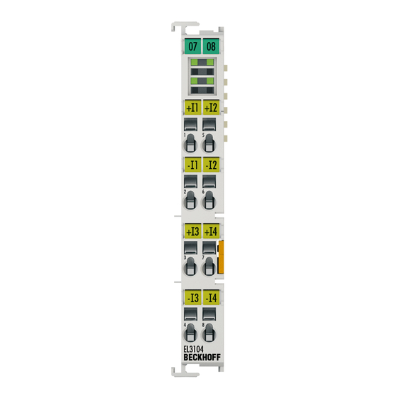
Mounting and wiring 4.11 LEDs and connection 4.11.1 EL310x - LEDs and connection Table of contents • LEDs [} 60] • Connection EL3101 [} 60] • Connection EL3102 [} 60] • Connection EL3104 [} 60] Fig. 36: EL3101 LEDs and Connection Version: 5.9 EL31xx-00xx... -
Page 59: Fig. 37 El3102 Leds And Connection
Mounting and wiring Fig. 37: EL3102 LEDs and Connection Fig. 38: EL3104 LEDs and Connection Current carrying capacity of the input contacts The maximum permitted current on the signal-relevant terminal points (inputs, GND) is 40 mA (if ap- plicable). EL31xx-00xx Version: 5.9... - Page 60 Outputs remain in safe state State of the EtherCAT State Machine: OP = normal operating state; mailbox and process data communication is possible *) If several RUN LEDs are present, all of them have the same function Connection EL3101 Terminal point Description Designation + Input 1...
-
Page 61: El311X - Leds And Connection
Mounting and wiring 4.11.2 EL311x - LEDs and connection Table of contents • LEDs [} 63] • Connection EL3111 [} 63] • Connection EL3112 [} 63] • Connection EL3114 [} 63] Fig. 39: EL3111 LEDs and Connection EL31xx-00xx Version: 5.9... -
Page 62: Fig. 40 El3112-00Xx Leds And Connection
Mounting and wiring Fig. 40: EL3112-00xx LEDs and Connection Fig. 41: EL3114 LEDs and Connection Current carrying capacity of the input contacts The maximum permitted current on the signal-relevant terminal points (inputs, GND) is 40 mA (if ap- plicable). Version: 5.9 EL31xx-00xx... - Page 63 Mounting and wiring LEDs Color Meaning RUN* green This LED indicates the terminal's operating state (if more than one RUN LED is present, all of them have the same function): State of the EtherCAT State Machine [} 36]: INIT = initialization of the terminal or BOOT- STRAP = function for firmware updates [} 211] of the terminal flashing State of the EtherCAT State Machine: PREOP = function for mailbox communication and dif-...
-
Page 64: El312X - Leds And Connection
Mounting and wiring 4.11.3 EL312x - LEDs and connection Table of contents • LEDs [} 66] • Connection EL3121 [} 67] • Connection EL3122 [} 67] • Connection EL3124, EL3124-0090 [} 67] Fig. 42: EL3121 LEDs and Connection Version: 5.9 EL31xx-00xx... -
Page 65: Fig. 43 El3122 Leds And Connection
Mounting and wiring Fig. 43: EL3122 LEDs and Connection Fig. 44: EL3124 LEDs and Connection EL31xx-00xx Version: 5.9... -
Page 66: Fig. 45 El3124-0090 Leds And Connection
Mounting and wiring Fig. 45: EL3124-0090 LEDs and Connection Current carrying capacity of the input contacts The maximum permitted current on the signal-relevant terminal points (inputs, GND) is 40 mA (if ap- plicable). LEDs Color Meaning RUN* green This LED indicates the terminal's operating state (if more than one RUN LED is present, all of them have the same function): State of the EtherCAT State Machine [} 36]: INIT = initialization of the terminal or BOOTSTRAP = function for firmware updates [} 211] of the terminal... - Page 67 Mounting and wiring Connection EL3121 Terminal point Description Designation + Input 1 + Input 1 - Input 1 - Input 1 Signal ground (internally connected to terminal point 7) Shield Shield (internally connected to terminal point 8) n.c. not connected n.c. not connected Signal ground (internally connected to terminal point 3) Shield Shield (internally connected to terminal point 4)
-
Page 68: El314X - Leds And Connection
Mounting and wiring 4.11.4 EL314x - LEDs and connection Table of contents • LEDs [} 69] • Connection EL3141 [} 69] • Connection EL3142 [} 70] • Connection EL3144 [} 70] Fig. 46: EL3141 LEDs and Connection Fig. 47: EL3142-00x0 LEDs and Connection Version: 5.9 EL31xx-00xx... -
Page 69: Fig. 48 El3144 Leds And Connection
Mounting and wiring Fig. 48: EL3144 LEDs and Connection LEDs Color Meaning RUN* green This LED indicates the terminal's operating state (if more than one RUN LED is present, all of them have the same function): State of the EtherCAT State Machine [} 36]: INIT = initialization of the terminal or BOOT- STRAP = function for firmware updates [} 211] of the terminal flashing State of the EtherCAT State Machine: PREOP = function for mailbox communication and... - Page 70 Mounting and wiring Connection EL3142-00x0 Terminal point Description Designation Input 1 Input 1 +24 V +24 V (internally connected to terminal point 6 and positive power contact) 0 V (internally connected to terminal point 7 and negative power contact) Shield Shield (internally connected to terminal point 8) Input 2 Input 2 +24 V...
-
Page 71: El315X - Leds And Connection
Mounting and wiring 4.11.5 EL315x - LEDs and connection Table of contents • LEDs [} 72] • Connection EL3151 [} 72] • Connection EL3152 [} 73] • Connection EL3154 [} 73] Fig. 49: EL3151 LEDs and Connection Fig. 50: EL3152 LEDs and Connection EL31xx-00xx Version: 5.9... -
Page 72: Fig. 51 El3154 Leds And Connection
Mounting and wiring Fig. 51: EL3154 LEDs and Connection LEDs Color Meaning RUN* green This LED indicates the terminal's operating state (if more than one RUN LED is present, all of them have the same function): State of the EtherCAT State Machine [} 36]: INIT = initialization of the terminal or BOOT- STRAP = function for firmware updates [} 211] of the terminal flashing State of the EtherCAT State Machine: PREOP = function for mailbox communication and dif-... - Page 73 Mounting and wiring Connection EL3152 Terminal point Description Designation Input 1 Input 1 +24 V +24 V (internally connected to terminal point 6 and positive power contact) 0 V (internally connected to terminal point 7 and negative power contact) Shield Shield (internally connected to terminal point 8) Input 2 Input 2 +24 V...
-
Page 74: El316X - Leds And Connection
Mounting and wiring 4.11.6 EL316x - LEDs and connection Table of contents • LEDs [} 75] • Connection EL3161 [} 75] • Connection EL3162 [} 76] • Connection EL3164 [} 76] Fig. 52: EL3161 LEDs and Connection Fig. 53: EL3162 LEDs and Connection Version: 5.9 EL31xx-00xx... -
Page 75: Fig. 54 El3164 Leds And Connection
Mounting and wiring Fig. 54: EL3164 LEDs and Connection LEDs Color Meaning RUN* green This LED indicates the terminal's operating state (if more than one RUN LED is present, all of them have the same function): State of the EtherCAT State Machine [} 36]: INIT = initialization of the terminal or BOOTSTRAP = function for firmware updates [} 211] of the terminal flashing State of the EtherCAT State Machine: PREOP = function for mailbox communication and different... - Page 76 Mounting and wiring Connection EL3162 Terminal point Description Designation Input 1 Input 1 +24 V +24 V (internally connected to terminal point 6 and positive power contact) 0 V (internally connected to terminal point 7 and negative power contact) Shield Shield (internally connected to terminal point 8) Input 2 Input 2 +24 V...
-
Page 77: El3174, El3174-00Xx - Leds And Connection
Mounting and wiring 4.11.7 EL3174, EL3174-00xx - LEDs and connection Table of contents • LEDs [} 78] • Connection EL3174, EL3174-0090 [} 78] • Connection EL3174-0002, EL3174-0032 [} 78] Fig. 55: EL3174, EL3174-0090 LEDs and Connection Fig. 56: EL3174-0002, EL3174-0032 LEDs and Connection EL31xx-00xx Version: 5.9... -
Page 78: Connection Notes For 20 Ma Measurement
Mounting and wiring LEDs Color Meaning RUN* green This LED indicates the terminal's operating state (if more than one RUN LED is present, all of them have the same function): State of the EtherCAT State Machine [} 36]: INIT = initialization of the terminal or BOOT- STRAP = function for firmware updates [} 211] of the terminal flashing State of the EtherCAT State Machine: PREOP = function for mailbox communication and dif-... -
Page 79: Fig. 57 Internal Connection Diagram 0/4
Mounting and wiring For the single-ended 20 mA inputs the terminal series EL304x, EL305x, EL314x, EL315x, EL317x, EL318x and EL375x they only apply with regard to technical transferability and also for devices whose analogue input channels have a common related ground potential (and therefore the channels are not to each other and/or not to power supply electrically isolated). -
Page 80: Fig. 58 Internal Connection Diagram For 0/4
Mounting and wiring Fig. 58: Internal connection diagram for 0/4..20 mA inputs of a EL3xx2 For all channels within the terminal U must not be exceeded. CM-max for 0/4..20 mA inputs If U of an analog input channel is exceeded, internal equalizing currents result in erroneous mea- surements. -
Page 81: Fig. 60 Example 1A, High-Side Measurement
Mounting and wiring If the EL30x1/EL30x2 or EL31x1/EL31x2 terminals have no external GND connection, the GND potential can adjust itself as required (referred to as "floating"). Please note that for this mode reduced measuring accuracy is to be expected. Example 1a Accordingly, this also applies if the floating point GND is connected to another potential. -
Page 82: Fig. 62 Invalid El3Xx4 Configuration
Mounting and wiring To rectify this, GND can in this case be connected externally with an auxiliary potential of 6 V relative to "0 V". The resulting A/GND will be in the middle, i.e. approx. 0.3 V or 11.6 V. Example 3 In the EL3xx4 terminals GND is internally connected with the negative power contact. -
Page 83: Commissioning
(or similar) of the Process Industries as its major task. In this role, the NAMUR releases the so called NE (proposed standards), each numbered continuously. Information with regard to the implementation of this recommendation in Beckhoff products are specified in sections “Technical data” and “Process data” of this documentation. -
Page 84: Notices On Analog Specifications
For analog I/O devices from Beckhoff the rule is that the limit with the largest value is chosen as the full scale value of the respective product (also called the reference value) and is given a positive sign. This applies to both symmetrical and asymmetrical measuring spans. -
Page 85: Temperature Coefficient Tk [Ppm/K]
A manufacturer can alleviate this by using components of a higher quality or by software means. The temperature coefficient, when indicated, specified by Beckhoff allows the user to calculate the expected measuring error outside the basic accuracy at 23 °C. -
Page 86: Single-Ended/Differential Typification
In particular this also applies to SE, even though the term suggest that only one wire is required. • The term "electrical isolation" should be clarified in advance. Beckhoff IO modules feature 1..8 or more analog channels; with regard to the channel connection a distinction is made in terms of: ◦... - Page 87 Commissioning ◦ Beckhoff terminals/ boxes (and related product groups) always feature electrical isolation between the field/analog side and the bus/EtherCAT side. In other words, if two analog terminals/ boxes are not connected via the power contacts (cable), the modules are effectively electrically isolated.
-
Page 88: Fig. 66 2-Wire Connection
+signal can be connected to +supply or –signal to –supply. - Yes: then you can connect accordingly to a Beckhoff ‘single-ended’ input. - No: the Beckhoff ‘differential’ input for +Signal and –Signal is to be selected; +Supply and – Supply are to be connected via additional cables. -
Page 89: Fig. 67 Connection Of Externally Supplied Sensors
Commissioning Fig. 67: Connection of externally supplied sensors Classification of the Beckhoff terminals/ boxes - Beckhoff 0/4-20 mA terminals/ boxes (and related product groups) are available as differential and single-ended terminals/ boxes (and related product groups): Single-ended Differential EL3x4x: 0-20 mA, EL3x5x: 4-20 mA; KL and related product EL3x1x: 0-20 mA, EL3x2x: 4-20 mA;... -
Page 90: Fig. 68 2-, 3- And 4-Wire Connection At Single-Ended And Differential Inputs
Commissioning Single-ended Differential Fig. 68: 2-, 3- and 4-wire connection at single-ended and differential inputs Version: 5.9 EL31xx-00xx... -
Page 91: Common-Mode Voltage And Reference Ground (Based On Differential Inputs)
Reference ground samples for Beckhoff IO devices: 1. Internal AGND fed out: EL3102/EL3112, resistive connection between the channels 2. 0V power contact: EL3104/EL3114, resistive connection between the channels and AGND; AGND connected to 0V power contact with low-resistance 3. -
Page 92: Temporal Aspects Of Analog/Digital Conversion
The conversion of the constant electrical input signal to a value-discrete digital and machine-readable form takes place in the analog Beckhoff EL/KL/EP input modules with ADC (analog digital converter). Although different ADC technologies are in use, from a user perspective they all have a common characteristic: after the conversion a certain digital value is available in the controller for further processing. - Page 93 This is the “external” view of the “Beckhoff AI channel” system – internally the signal delay in particular is composed of different components: hardware, amplifier, conversion itself, data transport and processing.
-
Page 94: Fig. 72 Diagram Signal Delay (Step Response)
Commissioning Fig. 72: Diagram signal delay (step response) 2.2 Signal delay (linear) Keyword: Group delay Describes the delay of a signal with constant frequency A test signal can be generated externally with a frequency generator, e.g. as sawtooth or sine. A simultaneous square wave signal would be used as reference. The signal delay [ms, µs] is then the interval between the applied electrical signal with a particular amplitude and the moment at which the analog process value reaches the same value. -
Page 95: Twincat Quick Start
• "offline": The configuration can be customized by adding and positioning individual components. These can be selected from a directory and configured. ◦ The procedure for offline mode can be found under http://infosys.beckhoff.com: TwinCAT 2 → TwinCAT System Manager → IO - Configuration → Adding an I/O Device •... -
Page 96: Fig. 74 Relationship Between User Side (Commissioning) And Installation
Commissioning ◦ See also http://infosys.beckhoff.com: Fieldbus components → Fieldbus cards and switches → FC900x – PCI Cards for Ethernet → Installation → Searching for devices The following relationship is envisaged from user PC to the individual control elements: Fig. 74: Relationship between user side (commissioning) and installation The user inserting of certain components (I/O device, terminal, box...) is the same in TwinCAT 2 and... -
Page 97: Fig. 75 Control Configuration With Embedded Pc, Input (El1004) And Output (El2008)
Commissioning Fig. 75: Control configuration with Embedded PC, input (EL1004) and output (EL2008) Note that all combinations of a configuration are possible; for example, the EL1004 terminal could also be connected after the coupler, or the EL2008 terminal could additionally be connected to the CX2040 on the right, in which case the EK1100 coupler wouldn’t be necessary. -
Page 98: Fig. 77 Selection Of The Target System
Commissioning Generally, TwinCAT can be used in local or remote mode. Once the TwinCAT system including the user interface (standard) is installed on the respective PLC, TwinCAT can be used in local mode and thereby the next step is "Insert Device [} 99]". If the intention is to address the TwinCAT runtime environment installed on a PLC as development environment remotely from another system, the target system must be made known first. -
Page 99: Fig. 79 Select "Scan Devices
Commissioning After confirmation with "OK" the target system can be accessed via the System Manager. Adding devices In the configuration tree of the TwinCAT 2 System Manager user interface on the left, select "I/O Devices” and then right-click to open a context menu and select "Scan Devices…", or start the action in the menu bar . -
Page 100: Fig. 81 Mapping Of The Configuration In The Twincat 2 System Manager
Commissioning Fig. 81: Mapping of the configuration in the TwinCAT 2 System Manager The whole process consists of two stages, which may be performed separately (first determine the devices, then determine the connected elements such as boxes, terminals, etc.). A scan can also be initiated by selecting "Device ..."... -
Page 101: Fig. 83 Twincat Plc Control After Startup
Commissioning • Graphical languages ◦ Function Block Diagram (FBD) ◦ Ladder Diagram (LD) ◦ The Continuous Function Chart Editor (CFC) ◦ Sequential Function Chart (SFC) The following section refers to Structured Text (ST). After starting TwinCAT PLC Control, the following user interface is shown for an initial project: Fig. 83: TwinCAT PLC Control after startup Sample variables and a sample program have been created and stored under the name "PLC_example.pro": EL31xx-00xx... -
Page 102: Fig. 84 Sample Program With Variables After A Compile Process (Without Variable Integration)
Commissioning Fig. 84: Sample program with variables after a compile process (without variable integration) Warning 1990 (missing "VAR_CONFIG") after a compile process indicates that the variables defined as external (with the ID "AT%I*" or "AT%Q*") have not been assigned. After successful compilation, TwinCAT PLC Control creates a "*.tpy"... -
Page 103: Fig. 86 Plc Project Integrated In The Plc Configuration Of The System Manager
Commissioning Select the PLC configuration "PLC_example.tpy" in the browser window that opens. The project including the two variables identified with "AT" are then integrated in the configuration tree of the System Manager: Fig. 86: PLC project integrated in the PLC configuration of the System Manager The two variables "bEL1004_Ch4"... - Page 104 Commissioning Fig. 88: Selecting PDO of type BOOL According to the default setting, certain PDO objects are now available for selection. In this sample the input of channel 4 of the EL1004 terminal is selected for linking. In contrast, the checkbox "All types" must be ticked for creating the link for the output variables, in order to allocate a set of eight separate output bits to a byte variable.
- Page 105 Commissioning Fig. 90: Application of a "Goto Link" variable, using "MAIN.bEL1004_Ch4" as a sample The process of assigning variables to the PDO is completed via the menu selection "Actions" → "Generate Mappings”, key Ctrl+M or by clicking on the symbol in the menu. This can be visualized in the configuration: The process of creating links can also take place in the opposite direction, i.e.
- Page 106 Commissioning Fig. 91: Choose target system (remote) In this sample "Runtime system 1 (port 801)" is selected and confirmed. Link the PLC with the real-time system via menu option "Online" → "Login", the F11 key or by clicking on the symbol . The control program can then be loaded for execution.
- Page 107 Commissioning Fig. 92: PLC Control logged in, ready for program startup The PLC can now be started via "Online" → "Run", F5 key or 5.3.2 TwinCAT 3 Startup TwinCAT makes the development environment areas available together with Microsoft Visual Studio: after startup, the project folder explorer appears on the left in the general window area (cf.
- Page 108 Commissioning Fig. 93: Initial TwinCAT 3 user interface First create a new project via (or under "File"→“New"→ "Project…"). In the following dialog make the corresponding entries as required (as shown in the diagram): Fig. 94: Create new TwinCAT project The new project is then available in the project folder explorer: Version: 5.9 EL31xx-00xx...
- Page 109 Commissioning Fig. 95: New TwinCAT3 project in the project folder explorer Generally, TwinCAT can be used in local or remote mode. Once the TwinCAT system including the user interface (standard) is installed on the respective PLC, TwinCAT can be used in local mode and thereby the next step is "Insert Device [} 110]".
- Page 110 Commissioning Use "Search (Ethernet)..." to enter the target system. Thus a next dialog opens to either: • enter the known computer name after "Enter Host Name / IP:" (as shown in red) • perform a "Broadcast Search" (if the exact computer name is not known) •...
- Page 111 Commissioning Fig. 99: Automatic detection of I/O devices: selection the devices to be integrated Confirm the message "Find new boxes", in order to determine the terminals connected to the devices. "Free Run" enables manipulation of input and output values in "Config mode" and should also be acknowledged. Based on the sample configuration [} 96] described at the beginning of this section, the result is as follows: Fig. 100: Mapping of the configuration in VS shell of the TwinCAT3 environment The whole process consists of two stages, which may be performed separately (first determine the devices,...
- Page 112 Commissioning Fig. 101: Reading of individual terminals connected to a device This functionality is useful if the actual configuration is modified at short notice. Programming the PLC TwinCAT PLC Control is the development environment for the creation of the controller in different program environments: TwinCAT PLC Control supports all languages described in IEC 61131-3.
- Page 113 Commissioning Fig. 102: Adding the programming environment in "PLC" In the dialog that opens select "Standard PLC project" and enter "PLC_example" as project name, for example, and select a corresponding directory: Fig. 103: Specifying the name and directory for the PLC programming environment The "Main"...
- Page 114 Commissioning Fig. 104: Initial "Main" program of the standard PLC project To continue, sample variables and a sample program have now been created: Version: 5.9 EL31xx-00xx...
- Page 115 Commissioning Fig. 105: Sample program with variables after a compile process (without variable integration) The control program is now created as a project folder, followed by the compile process: Fig. 106: Start program compilation The following variables, identified in the ST/ PLC program with "AT%", are then available in under "Assignments"...
- Page 116 Commissioning Fig. 107: Creating the links between PLC variables and process objects In the window that opens, the process object for the variable "bEL1004_Ch4" of type BOOL can be selected from the PLC configuration tree: Fig. 108: Selecting PDO of type BOOL According to the default setting, certain PDO objects are now available for selection.
- Page 117 Commissioning Fig. 109: Selecting several PDOs simultaneously: activate "Continuous" and "All types" Note that the "Continuous" checkbox was also activated. This is designed to allocate the bits contained in the byte of the variable "nEL2008_value" sequentially to all eight selected output bits of the EL2008 terminal. In this way it is possible to subsequently address all eight outputs of the terminal in the program with a byte corresponding to bit 0 for channel 1 to bit 7 for channel 8 of the PLC.
- Page 118 Commissioning Activation of the configuration The allocation of PDO to PLC variables has now established the connection from the controller to the inputs and outputs of the terminals. The configuration can now be activated with or via the menu under "TwinCAT"...
-
Page 119: Twincat 2
5.4.1 Installation of the TwinCAT real-time driver In order to assign real-time capability to a standard Ethernet port of an IPC controller, the Beckhoff real-time driver has to be installed on this port under Windows. This can be done in several ways. One option is described here. - Page 120 Commissioning Fig. 112: System Manager “Options” (TwinCAT 2) This have to be called up by the Menü “TwinCAT” within the TwinCAT 3 environment: Fig. 113: Call up under VS Shell (TwinCAT 3) The following dialog appears: Fig. 114: Overview of network interfaces Interfaces listed under “Compatible devices” can be assigned a driver via the “Install” button. A driver should only be installed on compatible devices.
- Page 121 Commissioning Fig. 115: EtherCAT device properties(TwinCAT 2): click on „Compatible Devices…“ of tab “Adapter” TwinCAT 3: the properties of the EtherCAT device can be opened by double click on “Device .. (EtherCAT)” within the Solution Explorer under “I/O”: After the installation the driver appears activated in the Windows overview for the network interface (Windows Start →...
- Page 122 Commissioning Fig. 117: Exemplary correct driver setting for the Ethernet port Other possible settings have to be avoided: Version: 5.9 EL31xx-00xx...
- Page 123 Commissioning Fig. 118: Incorrect driver settings for the Ethernet port EL31xx-00xx Version: 5.9...
- Page 124 Commissioning IP address of the port used IP address/DHCP In most cases an Ethernet port that is configured as an EtherCAT device will not transport general IP packets. For this reason and in cases where an EL6601 or similar devices are used it is useful to specify a fixed IP address for this port via the “Internet Protocol TCP/IP”...
-
Page 125: Notes Regarding Esi Device Description
The files are read (once) when a new System Manager window is opened, if they have changed since the last time the System Manager window was opened. A TwinCAT installation includes the set of Beckhoff ESI files that was current at the time when the TwinCAT build was created. - Page 126 1018 in the configuration. This is also stated by the Beckhoff compatibility rule. Refer in particular to the chapter ‘General notes on the use of Beckhoff EtherCAT IO components’ and for manual configuration to the chapter ‘Offline configuration creation’ [} 130].
- Page 127 Commissioning Fig. 123: File OnlineDescription.xml created by the System Manager Is a slave desired to be added manually to the configuration at a later stage, online created slaves are indicated by a prepended symbol “>” in the selection list (see Figure “Indication of an online recorded ESI of EL2521 as an example”).
- Page 128 Commissioning Reasons may include: • Structure of the *.xml does not correspond to the associated *.xsd file → check your schematics • Contents cannot be translated into a device description → contact the file manufacturer Version: 5.9 EL31xx-00xx...
-
Page 129: Twincat Esi Updater
Commissioning 5.4.3 TwinCAT ESI Updater For TwinCAT 2.11 and higher, the System Manager can search for current Beckhoff ESI files automatically, if an online connection is available: Fig. 126: Using the ESI Updater (>= TwinCAT 2.11) The call up takes place under: “Options” → "Update EtherCAT Device Descriptions"... -
Page 130: Offline Configuration Creation
Commissioning • the devices/modules be connected to the power supply and ready for communication • TwinCAT must be in CONFIG mode on the target system. The online scan process consists of: • detecting the EtherCAT device [} 135] (Ethernet port at the IPC) •... - Page 131 Commissioning This query may appear automatically when the EtherCAT device is created, or the assignment can be set/ modified later in the properties dialog; see Fig. “EtherCAT device properties (TwinCAT 2)”. Fig. 131: EtherCAT device properties (TwinCAT 2) TwinCAT 3: the properties of the EtherCAT device can be opened by double click on “Device .. (EtherCAT)” within the Solution Explorer under “I/O”: Selecting the Ethernet port Ethernet ports can only be selected for EtherCAT devices for which the TwinCAT real-time driver is...
- Page 132 (i.e. highest) revision and therefore the latest state of production is displayed in the selection dialog for Beckhoff devices. To show all device revisions available in the system as ESI descriptions tick the “Show Hidden Devices” check box, see Fig. “Display of previous revisions”.
- Page 133 If current ESI descriptions are available in the TwinCAT system, the last revision offered in the selection dialog matches the Beckhoff state of production. It is recommended to use the last device revision when creating a new configuration, if current Beckhoff devices are used in the real application. Older revisions should only be used if older devices from stock are to be used in the application.
- Page 134 Commissioning Fig. 137: EtherCAT terminal in the TwinCAT tree (left: TwinCAT 2; right: TwinCAT 3) Version: 5.9 EL31xx-00xx...
-
Page 135: Online Configuration Creation
Commissioning 5.4.6 ONLINE configuration creation Detecting/scanning of the EtherCAT device The online device search can be used if the TwinCAT system is in CONFIG mode. This can be indicated by a symbol right below in the information bar: • on TwinCAT 2 by a blue display “Config Mode” within the System Manager window: •... - Page 136 [} 140] with the defined initial configuration.Background: since Beckhoff occasionally increases the revision version of the delivered products for product maintenance reasons, a configuration can be created by such a scan which (with an identical machine construction) is identical according to the device list;...
- Page 137 Likewise, A might create spare parts stores worldwide for the coming series-produced machines with EL2521-0025-1018 terminals. After some time Beckhoff extends the EL2521-0025 by a new feature C. Therefore the FW is changed, outwardly recognizable by a higher FW version and a new revision -1019. Nevertheless the new device naturally supports functions and interfaces of the predecessor version(s);...
- Page 138 Commissioning Fig. 146: Manual triggering of a device scan on a specified EtherCAT device (left: TwinCAT 2; right: TwinCAT 3) In the System Manager (TwinCAT 2) or the User Interface (TwinCAT 3) the scan process can be monitored via the progress bar at the bottom in the status bar. Fig. 147: Scan progressexemplary by TwinCAT 2 The configuration is established and can then be switched to online state (OPERATIONAL).
- Page 139 Commissioning Fig. 151: Online display example Please note: • all slaves should be in OP state • the EtherCAT master should be in “Actual State” OP • “frames/sec” should match the cycle time taking into account the sent number of frames •...
- Page 140 A ‘ChangeTo’ or ‘Copy’ should only be carried out with care, taking into consideration the Beckhoff IO compatibility rule (see above). The device configuration is then replaced by the revision found; this can affect the supported process data and functions.
- Page 141 If current ESI descriptions are available in the TwinCAT system, the last revision offered in the selection dialog matches the Beckhoff state of production. It is recommended to use the last device revision when creating a new configuration, if current Beckhoff devices are used in the real application. Older revisions should only be used if older devices from stock are to be used in the application.
- Page 142 Commissioning Fig. 156: Correction dialog with modifications Once all modifications have been saved or accepted, click “OK” to transfer them to the real *.tsm configuration. Change to Compatible Type TwinCAT offers a function “Change to Compatible Type…” for the exchange of a device whilst retaining the links in the task.
-
Page 143: Ethercat Subscriber Configuration
Commissioning If called, the System Manager searches in the procured device ESI (in this example: EL1202-0000) for details of compatible devices contained there. The configuration is changed and the ESI-EEPROM is overwritten at the same time – therefore this process is possible only in the online state (ConfigMode). 5.4.7 EtherCAT subscriber configuration In the left-hand window of the TwinCAT 2 System Manager or the Solution Explorer of the TwinCAT 3... - Page 144 Commissioning „EtherCAT“ tab Fig. 161: „EtherCAT“ tab Type EtherCAT device type Product/Revision Product and revision number of the EtherCAT device Auto Inc Addr. Auto increment address of the EtherCAT device. The auto increment address can be used for addressing each EtherCAT device in the communication ring through its physical position.
- Page 145 For Beckhoff EtherCAT EL, ES, EM, EJ and EP slaves the following applies in general: • The input/output process data supported by the device are defined by the manufacturer in the ESI/XML description.
- Page 146 Commissioning Fig. 163: Configuring the process data Manual modification of the process data According to the ESI description, a PDO can be identified as “fixed” with the flag “F” in the PDO overview (Fig. “Configuring the process data”, J). The configuration of such PDOs cannot be changed, even if TwinCAT offers the associated dialog (“Edit”).
- Page 147 Commissioning Fig. 164: „Startup“ tab Column Description Transition Transition to which the request is sent. This can either be • the transition from pre-operational to safe-operational (PS), or • the transition from safe-operational to operational (SO). If the transition is enclosed in "<>" (e.g. <PS>), the mailbox request is fixed and cannot be modified or deleted by the user.
- Page 148 Commissioning Fig. 165: “CoE – Online” tab Object list display Column Description Index Index and sub-index of the object Name Name of the object Flags The object can be read, and data can be written to the object (read/write) The object can be read, but no data can be written to the object (read only) An additional P identifies the object as a process data object.
- Page 149 Commissioning Update List The Update list button updates all objects in the displayed list Auto Update If this check box is selected, the content of the objects is updated automatically. Advanced The Advanced button opens the Advanced Settings dialog. Here you can specify which objects are displayed in the list.
- Page 150 Commissioning „Online“ tab Fig. 167: „Online“ tab State Machine Init This button attempts to set the EtherCAT device to the Init state. Pre-Op This button attempts to set the EtherCAT device to the pre-operational state. This button attempts to set the EtherCAT device to the operational state.
- Page 151 • DC-Synchron Advanced Settings… Advanced settings for readjustment of the real time determinant TwinCAT- clock Detailed information to Distributed Clocks are specified on http://infosys.beckhoff.com: Fieldbus Components → EtherCAT Terminals → EtherCAT System documentation → EtherCAT basics → Distributed Clocks 5.4.7.1...
- Page 152 Commissioning • If the output Sync Manager (outputs) is selected in the Sync Manager list, all RxPDOs are displayed. • If the input Sync Manager (inputs) is selected in the Sync Manager list, all TxPDOs are displayed. The selected entries are the PDOs involved in the process data transfer. In the tree diagram of the System Manager these PDOs are displayed as variables of the EtherCAT device.
-
Page 153: General Notes - Ethercat Slave Application
Commissioning General Notes - EtherCAT Slave Application This summary briefly deals with a number of aspects of EtherCAT Slave operation under TwinCAT. More detailed information on this may be found in the corresponding sections of, for instance, the EtherCAT System Documentation. Diagnosis in real time: WorkingCounter, EtherCAT State and Status Generally speaking an EtherCAT Slave provides a variety of diagnostic information that can be used by the controlling task. - Page 154 Fig. “Basic EtherCAT Slave Diagnosis in the PLC” shows an example of an implementation of basic EtherCAT Slave Diagnosis. A Beckhoff EL3102 (2-channel analogue input terminal) is used here, as it offers both the communication diagnosis typical of a slave and the functional diagnosis that is specific to a channel.
- Page 155 Commissioning Code Function Implementation Application/evaluation The EtherCAT Master's diagnostic infor- At least the DevState is to be evaluated for mation the most recent cycle in the PLC. updated acyclically (yellow) or provided The EtherCAT Master's diagnostic informa- acyclically (green). tion offers many more possibilities than are treated in the EtherCAT System Documenta- tion.
- Page 156 Commissioning Fig. 171: EL3102, CoE directory EtherCAT System Documentation The comprehensive description in the EtherCAT System Documentation (EtherCAT Basics --> CoE Interface) must be observed! A few brief extracts: • Whether changes in the online directory are saved locally in the slave depends on the device. EL terminals (except the EL66xx) are able to save in this way.
- Page 157 Commissioning Fig. 172: Example of commissioning aid for a EL3204 This commissioning process simultaneously manages • CoE Parameter Directory • DC/FreeRun mode • the available process data records (PDO) Although the "Process Data", "DC", "Startup" and "CoE-Online" that used to be necessary for this are still displayed, it is recommended that, if the commissioning aid is used, the automatically generated settings are not changed by it.
- Page 158 Commissioning Standard setting The advanced settings of the EtherCAT Master are set as standard: • EtherCAT Master: OP • Slaves: OP This setting applies equally to all Slaves. Fig. 173: Default behaviour of the System Manager In addition, the target state of any particular Slave can be set in the "Advanced Settings" dialogue; the standard setting is again OP.
- Page 159 Commissioning Manual Control There are particular reasons why it may be appropriate to control the states from the application/task/PLC. For instance: • for diagnostic reasons • to induce a controlled restart of axes • because a change in the times involved in starting is desirable In that case it is appropriate in the PLC application to use the PLC function blocks from the TcEtherCAT.lib, which is available as standard, and to work through the states in a controlled manner using, for instance, FB_EcSetMasterState.
- Page 160 Commissioning Fig. 176: Illegally exceeding the E-Bus current From TwinCAT 2.11 and above, a warning message "E-Bus Power of Terminal..." is output in the logger window when such a configuration is activated: Fig. 177: Warning message for exceeding E-Bus current NOTE Caution! Malfunction possible! The same ground potential must be used for the E-Bus supply of all EtherCAT terminals in a terminal block! Version: 5.9 EL31xx-00xx...
-
Page 161: Process Data And Operation Modes
Commissioning Process data and operation modes 5.6.1 Parameterization An EL31xx is parameterized via 2 dialog boxes/tabs in the TwinCAT System Manager, the Process Data tab (A) for the communication-specific settings and the CoE directory (B) for the settings in the slave. Fig. 178: EL31xx parameterization •... - Page 162 Commissioning Input signal Value EL310x EL311x, EL3112-0011 EL312x, EL316x Decimal Hexadecimal EL314x EL315x 10 V 20 mA 20 mA 20 mA 10 V 32767 0x7FFF 10 mA 10 mA 12 mA 16383 0x3FFF 0 mA 0 mA 4 mA 0x0000 -5 V -10 mA -16383...
-
Page 163: Fig. 179 Input Byte Definition
Commissioning 5.6.2.2 Siemens bits, index 0x80n0:05 Siemens bits, index 0x80n0:05 [} 194] If this bit is set, status displays are superimposed on the lowest three bits. In the error case "overrange" or "underrange", bit 0 is set. 5.6.2.3 Undershoot and overshoot of the measuring range (under-range, over- range), index 0x60n0:01, 0x60n0:02 Undershoot and overshoot of the measuring range (under-range, over-range), index 0x60n0:01 [} 196], 0x60n0:02 [} 196]... -
Page 164: Fig. 180 Linking Of 2-Bit Variable To Additional Task
Commissioning Fig. 180: Linking of 2-bit variable to additional task Example for EL3162: Channel 1; Limit 1 and Limit 2 enabled, Limit 1 = 2.8 V, Limit 2 = 7.4 V, representation: signed integer Entry in index (Limit 1): 0x8000:13 [} 194] (2.8 V / 10 V) x 2 / 2 - 1 = 9.174 Entry in index (Limit 2): 0x8000:14 [} 194] (7.4 V / 10 V) x 2... -
Page 165: Fig. 181 Relationship Of Operating Modes
Commissioning Terminal Swap limit function from EL31x1, EL31x4 All firmware versions EL3112-0011 All firmware versions EL3102 Firmware 08 EL3112 Firmware 08 EL3122 Firmware 08 EL3142 Firmware 08 EL3152 Firmware 09 EL3162 Firmware 08 EL3174, EL3174-00xx All firmware versions 5.6.2.5 Operating modes The EL30xx and the EL31xx accordingly supports three different operating modes: Freerun (filter on, timer interrupt), Synchron (filter off, SyncManager interrupt) and DC (DC Sync interrupt) Fig. 181: Relationship of operating modes... - Page 166 Commissioning The operating modes of the EL30xx are: Mode 1 (default) Filter (Index: On (default.: 50 Hz 0x8000:06) FIR) Distributed Clocks mode Possible with EL30xx Possible with EL30xx Default setting EL30xx EL31xx Synchronization 0: FreeRun (default) 0: FreeRun (default) 1: Frame triggered (SM3 in- 3: DC mode mode puts) (index:0x1C33:01...
- Page 167 Commissioning Combinations of filters, FastOp mode and Synchronization mode Other combination options of filter, FastOp mode and Synchronization mode are expressly not rec- ommended. Synchron mode In synchronous operation process data are generated frame-triggered, so that a new value is available with each PLC cycle.
-
Page 168: Fig. 182 Attenuation Curve Notch.filter At 50 Hz
Commissioning Fig. 182: Attenuation curve notch.filter at 50 Hz Filter data for FIR filter (1 to 4-channel terminals) Filter Attenuation Limit frequency (-3 dB) Conversion time 50 Hz FIR > 50 dB 22 Hz 625 µs 60 Hz FIR > 45 dB 26 Hz 521 µs IIR filter The filter with IIR characteristics is a discrete time, linear, time invariant filter that can be set to eight levels (level 1 = weak recursive filter, up to level 8 = strong recursive filter). -
Page 169: Process Data
Commissioning 5.6.3 Process data Table of contents • Interpretation of value & status variable [} 169] • Status word [} 170] • Changeover of process data sets [} 171] • Note about TwinCAT 2.10 [} 174] • Password protection for user calibration [} 175] The EL31xx terminals offer two different process data per analog channel for transmission: the analog value Value (16 bit) and status information (16 bit). - Page 170 Commissioning Fig. 185: Display of the subvariables of the EL3102-0000-0016 from TwinCAT 2.11 build 1544 onwards Control/status word Status word The status word (SW) is located in the input process image, and is transmitted from terminal to the controller. SW.15 SW.14 SW.13 SW.12 SW.11...
- Page 171 Commissioning Legend Name Description SW.15 TxPDO Toggle Toggles with each new analog process value SW.14 TxPDO State TRUE in the case of an internal error SW.13* Sync error TRUE (DC mode): a synchronization error occurred in the expired cycle. SW.6 ERROR General error bit, is set together with overrange and underrange SW.5...
-
Page 172: Fig. 185 Display Of The Subvariables Of The El3102-0000-0016 From Twincat 2.11 Build 1544 Onwards 170 Fig. 186 Predefined Pdo Assignment In The El3102-0000-0016
Commissioning Fig. 186: Predefined PDO assignment in the EL3102-0000-0016 All channels of the EL31x2 are simultaneously set to legacy, legacy compact, standard or compact process image. Selective PDO selection All TwinCAT versions support the selective selection of individual PDOs, as defined in the XML description. Exclusion criteria prevent irregular combinations. -
Page 173: Fig. 187 Selective Pdo Selection
Note about the 1-byte status of earlier EtherCAT terminals Previous analog input terminals from Beckhoff (e.g. EL31x2) had a status byte instead of the status word that is now implemented and therefore a 3-byte interface. 8 additional bits now offer extended diagnostic options, wherein the default process image of the EL31xx now encompasses 4 bytes, status word and value word. -
Page 174: Fig. 188 3-Byte Interface Of The El31X2
Commissioning Fig. 188: 3-byte interface of the EL31x2 If the 3-byte interface for linking to the analogue input channel is implemented in existing PLC projects, the TwinCAT System Manager nevertheless offers the possibility to link the EL31xx with a 4-byte interface. To do this, open the link dialog as usual by double-clicking on the variable and activate the AllTypes checkbox. -
Page 175: Fig. 190 Element-Orientated Process Image Under Twincat 2.10
Commissioning Fig. 190: Element-orientated process image under TwinCAT 2.10 Password protection for user data Several user data is protected for unrequested or mistaken write access by a password to be entered within CoE 0xF009: • CoE write access by the user, PLC or start up entries in Single- or CompleteAccess access •... - Page 176 Commissioning The password protection is provided for following user data Protect-able CoE object Terminals 0x80n0:17 (User Calibration Offset) EL31xx, 0x80n0:18 (User Calibration Gain) ELX31xx 0x80nD:17, (Low Range Error) EL3174, EL3174-00xx, 0x80nD:18 (High Range Error) EL318x, ELX3181 Application of CoE 0xF009 •...
-
Page 177: Data Stream And Measurement Ranges
Calculation of process data The concept “calibration”, which has historical roots at Beckhoff, is used here even if it has nothing to do with the deviation statements of a calibration certificate. Actually, this is a description of the vendor or customer calibration data/adjustment data used by the device during operation in order to maintain the assured measuring accuracy. -
Page 178: Fig. 193 Measurement Ranges ± 10 V, ± 10 Ma And ± 20 Ma (Applicable As Given By 'X' By The Follow- Ing Table)
Commissioning Name Designation Index Output value of the A/D converter 0x80nE:01 [} 195] Output value after the filter Vendor calibration offset (not changeable) 0x80nF:01 [} 195] Vendor calibration gain (not changeable) 0x80nF:02 [} 195] User calibration offset (can be activated via index 0x80n0:0A [} 194]) 0x80n0:17 [} 194] User calibration gain (can be activated via index 0x80n0:0A [} 194]) 0x80n0:18 [} 194]... -
Page 179: Fig. 194 Measurement Range 0
Commissioning Terminal Measurement range ± 10 V ± 10 mA ± 20 mA EL310x EL3112-0011 EL3142-0010 EL311x, EL314x Fig. 194: Measurement range 0...20 mA EL312x, EL315x Fig. 195: Measurement range 4...20 mA EL316x Fig. 196: Measurement range 0...10 V EL31xx-00xx Version: 5.9... -
Page 180: Fig. 197 El3174, El3174-0002, El3174-0090: Measurement Range -10
Commissioning EL3174, EL3174-00xx scaler: extended range/ legacy range The EL3174 or the EL3174-00xx terminal respectively has the scaler (AI Advanced settings Object 0x80nD:12 [} 195]) “Extended Range” default set. This type of scaling allows an exceeding of the positive or negative value of approx. 7%. The technical useable range is within -107% to +107% of the respective full scale value. -
Page 181: Fig. 198 El3174-0032: Measurement Range -3
Commissioning Measurement range ±3 V (bipole): Fig. 198: EL3174-0032: measurement range -3…+3 V Measurement range 0…10 V (unipole): Fig. 199: EL3174, EL3174-0002, EL3174-0090: measurement range 0…10 V EL31xx-00xx Version: 5.9... -
Page 182: Fig. 200 El3174-0032: Measurement Range 0
Commissioning Measurement range 0…3 V (unipole): Fig. 200: EL3174-0032: measurement range 0…3 V Measurement range ±20 mA (bipole): Fig. 201: EL3174, EL3174-00xx: measurement range -20…+20 mA Version: 5.9 EL31xx-00xx... -
Page 183: Fig. 202 El3174, El3174-00Xx: Measurement Range 0
Commissioning Measurement range 0...20 mA (current loop): Fig. 202: EL3174, EL3174-00xx: measurement range 0…20 mA Measurement range 4...20 mA (current loop): Fig. 203: EL3174, EL3174-00xx: measurement range 4…20 mA EL31xx-00xx Version: 5.9... -
Page 184: Fast Mode
5.6.5 Fast mode The Fast mode in Beckhoff EtherCAT Terminals has developed historically and is an operating mode with which EL Terminals, primarily the EL31xx and EL41xx groups (analog input/output terminals), can be operated with a considerably faster conversion time. Hence, an analog input value can be converted more quickly/more often or output via the controller accordingly. -
Page 185: Fig. 205 Switch Input Channel On And Off
FastMode by means of channel deactivation Example 1 You can switch the second input channel on and off on the Process data tab of the EL3101 under PDO assignment with the aid of the check box (see the red arrow). -
Page 186: Twinsafe Sc
Commissioning Fig. 206: Switch output channel on and off FastMode by means of CoE deactivation To disable CoE support for input terminals, a must be entered in the StartUp list in the System Manager for the terminal. This deactivates the CoE later in SAFEOP and OP. -
Page 187: Twinsafe Sc Configuration
Commissioning The TwinSAFE SC technology enables communication via the Safety-over-EtherCAT protocol. These connections use another CRC, in order to be able to distinguish between TwinSAFE SC and TwinSAFE. TwinSAFE SC Terminals are identified with a yellow line at the side of the housing front panel. The data of the TwinSAFE SC terminals are transferred to the TwinSAFE logic for secure processing in multiple channels. -
Page 188: Fig. 209 Adding A Twinsafe Sc Connection
Commissioning Fig. 209: Adding a TwinSAFE SC connection After opening the alias device by double-clicking, select the Link button next to Physical Device, in order to create the link to a TwinSAFE SC terminal. Only suitable TwinSAFE SC terminals are offered in the selection dialog. -
Page 189: Fig. 211 Selecting A Free Crc
Commissioning Fig. 211: Selecting a free CRC These settings must match the settings in the CoE objects of the TwinSAFE SC component. The TwinSAFE SC component initially makes all available process data available. The Safety Parameters tab typically contains no parameters. The process data size and the process data themselves can be selected under the Process Image tab. -
Page 190: Fig. 213 Selection Of The Process Data
Commissioning Fig. 213: Selection of the process data The safety address together with the CRC must be entered on the TwinSAFE SC slave side. This is done via the CoE objects under TSC settings of the corresponding TwinSAFE SC component (here, for example, EL5021-0090, 0x8010: 01 and 0x8010: 02). -
Page 191: Twinsafe Sc Process Data El31X4-0090
EtherCAT XML Device Description The display matches that of the CoE objects from the EtherCAT XML Device Description. We rec- ommend downloading the latest XML file from the download area of the Beckhoff website and in- stalling it according to installation instructions. -
Page 192: Restore Object
0x4000. The settings objects in the range 0x4000 no longer show up in the CoE overview from the following FW versions, although they are still func- tionally supported: EL3101-0000 FW12 EL3112-0000 FW13 EL3122-0000 FW13 EL3142-0000 FW13 EL3142-0010 FW11... - Page 193 Commissioning Index 40n2 calibration data (for n = 4 [channel 1], n = 8 [channel 2]) (up to rev. no. EL31x2-0000-0016, only for EL31x2, see note [} 191]) Index (hex) Name Meaning Flags Default 40n2:0 Calibration data Length of this object 40n2:01 Offset 16 bit These objects are used to trim the tolerances of the com- Offset trim...
- Page 194 Commissioning Enum value Decimal value Description Default 50 Hz FIR 50 Hz FIR over 32 values; 50 Hz interferences are suppressed with 60 dB 50 Hz FIR (0 60 Hz FIR 60 Hz FIR over 32 values; 60 Hz interferences are suppressed with 40 dB IIR Level 1 Recursive filter, t = 0.72 ms rise_90%...
- Page 195 Commissioning ***) since revision no. EL31xx-00xx-0016 The filter characteristics are set via index 0x8000:15 [} 194] The filter frequencies are set for all channels of the EL31xx terminals centrally via index 0x8000:15 [} 194] (channel 1). All other corresponding indices 0x80n0:15 have no parameterization function! Index 80nD AI Advanced settings (for 0 ≤...
-
Page 196: Input Data
Commissioning 5.8.3 Input data Index 3101 inputs (channel 1) (up to rev. no. EL31x2-0000-0016, only for EL31x2, see note [} 191]) Index (hex) Name Meaning Flags Default 3101:0 Inputs Length of this object 3101:01 Status Status byte [} 170] channel 1 3101:02 Value Input process data channel 1 Index 3102 inputs (channel 2) -
Page 197: Output Data
Commissioning 5.8.4 Output data The EL31xx have no output objects 5.8.5 Standard objects The standard objects have the same meaning for all EtherCAT slaves. Index 1000 Device type Index (hex) Name Meaning Data type Flags Default 1000:0 Device type Device type of the EtherCAT slave: the Lo-Word con- UINT32 0x012C1389 tains the CoE profile used (5001). - Page 198 Commissioning Index (hex) Name Meaning Data type Flags Default 180n:0 AI TxPDO-Par Stan- PDO parameter TxPDO UINT8 0x06 (6 dard 180n:06 Exclude TxPDOs Specifies the TxPDOs (index of TxPDO OCTET-STRING[2] n= Wert mapping objects) that must not be trans- 0x021A ferred together with this PDO 0x031A 0x101A...
- Page 199 Commissioning Index 1A0n AI TxPDO-Map Standard (for n = 0, 2, 4, 6; p = 0, 1, 2, 3; depending on the number of channels, not applicable for EL31x2) Index (hex) Name Meaning Data type Flags Default 1A0n:0 AI TxPDO-Map stan- PDO Mapping TxPDO UINT8 0x0B (11...
- Page 200 Commissioning Index 1A0n*** AI TxPDO-Map Standard (for n = 2, 4 p = 0, 1; only for EL31x2) Index (hex) Name Meaning Data type Flags Default 1A0n:0 AI TxPDO-Map stan- PDO Mapping TxPDO UINT8 0x0B (11 dard 1A0n:01 SubIndex 001 1. PDO Mapping entry (object 0x60p0 (AI Inputs), entry UINT32 0x60p0:01, 1 0x01 (Underrange))
- Page 201 Commissioning Index 1C13 TxPDO assign (not applicable for EL31x2) For operation on masters other than TwinCAT it must be ensured that the channels are entered in the PDO assignment (“TxPDO assign”, object 0x1C13) successively. Index (hex) Name Meaning Data type Flags Default 1C13:0...
- Page 202 Commissioning Index 1C33*** SM input parameter Index (hex) Name Meaning Data type Flags Default 1C33:0 SM input parameter Synchronization parameters for the inputs UINT8 0x20 (32 1C33:01 Sync mode Current synchronization mode: UINT16 0x0001 (1 • Bit 0 = 0: Free Run •...
-
Page 203: Objects Twinsafe Single Channel (El31X4-0090)
Commissioning Index F000*** Modular device profile Index (hex) Name Meaning Data type Flags Default F000:0 Modular device profile General information for the modular device profile UINT8 0x02 (2 F000:01 Module index distance Index spacing of the objects of the individual channels UINT16 0x0010 (16 F000:02 Maximum number of... -
Page 204: Error Messages And Diagnosis
Commissioning Index 1A08 TxPDO-Map Slave Message Index (hex) Name Meaning Data type Flags Default 1A08:0 TxPDO-Map Slave PDO Mapping TxPDO UINT8 0x0A (10 Message 1A08:01 SubIndex 001 1. PDO Mapping entry (object 0x6040 (TSC Slave UINT32 0x6040:01, 8 Frame Elements), entry 0x01 (TSC__Slave Cmd)) 1A08:02 SubIndex 002 2. -
Page 205: Fig. 216 Twincat Logger Window, Example Of Incorrect Startup Entry Under Twincat 2.11
OCAL_CONTROL CoE 1C33: Contents locked because filter active The Beckhoff TwinCAT EtherCAT master outputs the slave error message according to the ETG specification in plain text in the logger window: Fig. 216: TwinCAT logger window, example of incorrect StartUp entry under TwinCAT 2.11... -
Page 206: Appendix
Note • It is recommended to use the newest possible firmware for the respective hardware. • Beckhoff is not under any obligation to provide customers with free firmware updates for delivered products. NOTE Risk of damage to the device! Pay attention to the instructions for firmware updates on the separate page [} 211]. - Page 207 Appendix EL3104 Hardware (HW) Firmware (FW) Revision no. Date of release 00 - 12* EL3104-0000-0016 2010/07 2011/01 2012/03 EL3104-0000-0017 2012/07 EL3104-0000-0018 2013/12 EL3104-0000-0019 2016/06 EL3104-0000-0020 2017/02 EL3111 Hardware (HW) Firmware (FW) Revision no. Date of release 00 - 07* EL3111-0000-0016 2010/09 EL3111-0000-0017 2012/08...
- Page 208 Appendix EL3121 Hardware (HW) Firmware (FW) Revision no. Date of release 00 - 07* EL3121-0000-0016 2010/09 EL3121-0000-0017 2012/08 EL3121-0000-0018 2013/12 EL3121-0000-0019 2017/02 EL3122 Hardware (HW) Firmware (FW) Revision no. Date of release 00 - 02 EL3122-0000-0000 2005/09 02 - 13* EL3122-0000-0016 2010/04 EL3122-0000-0017...
- Page 209 Appendix EL3142 Hardware (HW) Firmware (FW) Revision no. Date of release 05 - 10 EL3142-0000-0000 2005/02 10 - 23* EL3142-0000-0016 2010/04 EL3142-0000-0017 2010/06 2010/10 2011/01 2012/03 EL3142-0000-0018 2012/10 2013/05 EL3142-0000-0019 2014/05 EL3142-0010 Hardware (HW) Firmware (FW) Revision no. Date of release 02 - 15* EL3142-0010-0017 2010/09...
- Page 210 Appendix EL3152 Hardware (HW) Firmware (FW) Revision no. Date of release 04 - 09 EL3152-0000-0000 2005/02 2005/03 09 - 22* EL3152-0000-0016 2010/04 EL3152-0000-0017 2010/06 2010/06 2010/10 2011/01 2011/04 2012/03 EL3152-0000-0018 2012/10 EL3152-0000-0019 2014/05 EL3154 Hardware (HW) Firmware (FW) Revision no. Date of release 00 - 11* EL3154-0000-0016...
-
Page 211: Firmware Update El/Es/Em/Epxxxx
Check on the Beckhoff web page whether more up-to-date documentation is available. Firmware Update EL/ES/EM/EPxxxx This section describes the device update for Beckhoff EtherCAT slaves from the EL/ES, EM, EK and EP series. A firmware update should only be carried out after consultation with Beckhoff support. -
Page 212: Device Description Esi File/Xml
Appendix Simplified update by bundle firmware The update using so-called bundle firmware is more convenient: in this case the controller firmware and the ESI description are combined in a *.efw file; during the update both the firmware and the ESI are changed in the terminal. -
Page 213: Fig. 218 Scan The Subordinate Field By Right-Clicking On The Ethercat Device
The device revision is closely linked to the firmware and hardware used. Incompatible combinations lead to malfunctions or even final shutdown of the device. Corresponding updates should only be carried out in consultation with Beckhoff support. Display of ESI slave identifier... -
Page 214: Fig. 220 Change Dialog
Appendix Fig. 220: Change dialog In this example in Fig. Change dialog, an EL3201-0000-0017 was found, while an EL3201-0000-0016 was configured. In this case the configuration can be adapted with the Copy Before button. The Extended Information checkbox must be set in order to display the revision. Changing the ESI slave identifier The ESI/EEPROM identifier can be updated as follows under TwinCAT: •... -
Page 215: Firmware Explanation
• offline: The EtherCAT Slave Information ESI/XML may contain the default content of the CoE. This CoE directory can only be displayed if it is included in the ESI (e.g. "Beckhoff EL5xxx.xml"). The Advanced button must be used for switching between the two views. -
Page 216: Updating Controller Firmware *.Efw
Appendix Fig. 223: Display of EL3204 firmware version In (A) TwinCAT 2.11 shows that the Online CoE directory is currently displayed. If this is not the case, the Online directory can be loaded via the Online option in Advanced Settings (B) and double-clicking on AllObjects. -
Page 217: Fpga Firmware *.Rbf
Appendix Proceed as follows, unless instructed otherwise by Beckhoff support. Valid for TwinCAT 2 and 3 as EtherCAT master. • Switch TwinCAT system to ConfigMode/FreeRun with cycle time >= 1 ms (default in ConfigMode is 4 ms). A FW-Update during real time operation is not recommended. - Page 218 Appendix The firmware version number included in the terminal serial number contains both firmware components. If one of these firmware components is modified this version number is updated. Determining the version via the System Manager The TwinCAT System Manager indicates the FPGA firmware version. Click on the Ethernet card of your EtherCAT strand (Device 2 in the example) and select the Online tab.
- Page 219 Older firmware versions can only be updated by the manufacturer! Updating an EtherCAT device The following sequence order have to be met if no other specifications are given (e.g. by the Beckhoff support): • Switch TwinCAT system to ConfigMode/FreeRun with cycle time >= 1 ms (default in ConfigMode is 4 ms).
- Page 220 Appendix • In the TwinCAT System Manager select the terminal for which the FPGA firmware is to be updated (in the example: Terminal 5: EL5001) and click the Advanced Settings button in the EtherCAT tab: • The Advanced Settings dialog appears. Under ESC Access/E²PROM/FPGA click on Write FPGA button: Version: 5.9 EL31xx-00xx...
-
Page 221: Simultaneous Updating Of Several Ethercat Devices
Appendix • Select the file (*.rbf) with the new FPGA firmware, and transfer it to the EtherCAT device: • Wait until download ends • Switch slave current less for a short time (don't pull under voltage!). In order to activate the new FPGA firmware a restart (switching the power supply off and on again) of the EtherCAT device is required. -
Page 222: Restoring The Delivery State
Appendix Restoring the delivery state To restore the delivery state for backup objects in ELxxxx terminals, the CoE object Restore default parameters, SubIndex 001 can be selected in the TwinCAT System Manager (Config mode) (see Fig. Selecting the Restore default parameters PDO) Fig. 229: Selecting the "Restore default parameters"... -
Page 223: Support And Service
Beckhoff's branch offices and representatives Please contact your Beckhoff branch office or representative for local support and service on Beckhoff products! The addresses of Beckhoff's branch offices and representatives round the world can be found on her internet pages: http://www.beckhoff.com You will also find further documentation for Beckhoff components there. - Page 224 Startup list in the TwinCAT System Manager ................Fig. 22 Offline list ............................. Fig. 23 Online list ............................ Fig. 24 Spring contacts of the Beckhoff I/O components................. Fig. 25 Attaching on mounting rail ......................Fig. 26 Disassembling of terminal......................Fig. 27 Power contact on left side......................
- Page 225 List of illustrations Fig. 42 EL3121 LEDs and Connection ....................Fig. 43 EL3122 LEDs and Connection ....................Fig. 44 EL3124 LEDs and Connection ....................Fig. 45 EL3124-0090 LEDs and Connection ................... Fig. 46 EL3141 LEDs and Connection ....................Fig. 47 EL3142-00x0 LEDs and Connection ...................
- Page 226 List of illustrations Fig. 88 Selecting PDO of type BOOL ...................... 104 Fig. 89 Selecting several PDOs simultaneously: activate "Continuous" and "All types"......104 Fig. 90 Application of a "Goto Link" variable, using "MAIN.bEL1004_Ch4" as a sample ......105 Fig. 91 Choose target system (remote) ....................
- Page 227 List of illustrations Fig. 134 Display of device revision ......................132 Fig. 135 Display of previous revisions ...................... 133 Fig. 136 Name/revision of the terminal ...................... 133 Fig. 137 EtherCAT terminal in the TwinCAT tree (left: TwinCAT 2; right: TwinCAT 3)......134 Fig.
- Page 228 List of illustrations Fig. 178 EL31xx parameterization ......................161 Fig. 179 Input byte definition........................163 Fig. 180 Linking of 2-bit variable to additional task..................164 Fig. 181 Relationship of operating modes ....................165 Fig. 182 Attenuation curve notch.filter at 50 Hz..................168 Fig.
- Page 229 List of illustrations Fig. 223 Display of EL3204 firmware version .................... 216 Fig. 224 Firmware Update ......................... 216 Fig. 225 FPGA firmware version definition ....................218 Fig. 226 Context menu Properties ......................218 Fig. 227 Dialog Advanced Settings ......................219 Fig.
Need help?
Do you have a question about the EL3101 and is the answer not in the manual?
Questions and answers