
Subscribe to Our Youtube Channel
Related Manuals for Beckhoff EL34x3 Series


Summary of Contents for Beckhoff EL34x3 Series
- Page 1 Documentation EL34x3 3-phase power measurement terminal Version: Date: 2019-03-28...
-
Page 3: Table Of Contents
Table of contents Table of contents 1 Foreword .............................. 7 Product overview - Power measurement terminals ................ 7 Notes on the documentation...................... 7 Safety instructions .......................... 9 Documentation issue status ...................... 10 Version identification of EtherCAT devices .................. 11 2 Product overview............................. 16 EL3413 ............................ 16 2.1.1 Introduction ........................ 16 2.1.2 Technical data ......................... - Page 4 Table of contents 4.7.3 EL3413-0120 ........................ 56 4.7.4 EL3433-0000 ........................ 59 5 Commissioning............................ 62 TwinCAT Quick Start ........................ 62 5.1.1 TwinCAT 2 ........................ 65 5.1.2 TwinCAT 3 ........................ 75 TwinCAT Development Environment .................... 87 5.2.1 Installation of the TwinCAT real-time driver.............. 87 5.2.2 Notes regarding ESI device description................ 93 5.2.3 TwinCAT ESI Updater .....................
- Page 5 Table of contents 7.3.1 Device description ESI file/XML.................. 185 7.3.2 Firmware explanation .................... 188 7.3.3 Updating controller firmware *.efw................. 189 7.3.4 FPGA firmware *.rbf....................... 190 7.3.5 Simultaneous updating of several EtherCAT devices............ 194 Restoring the delivery state ...................... 195 Support and Service ........................ 196 EL34x3 Version: 4.4...
- Page 6 Table of contents Version: 4.4 EL34x3...
-
Page 7: Foreword
, TwinSAFE , XFC and XTS registered trademarks of and licensed by Beckhoff Automation GmbH. Other designations used in this publication may be trademarks whose use by third parties for their own purposes could violate the rights of the owners. - Page 8 Foreword ® EtherCAT is registered trademark and patented technology, licensed by Beckhoff Automation GmbH, Germany. Copyright © Beckhoff Automation GmbH & Co. KG, Germany. The reproduction, distribution and utilization of this document as well as the communication of its contents to others without express authorization are prohibited.
-
Page 9: Safety Instructions
All the components are supplied in particular hardware and software configurations appropriate for the application. Modifications to hardware or software configurations other than those described in the documentation are not permitted, and nullify the liability of Beckhoff Automation GmbH & Co. KG. Personnel qualification This description is only intended for trained specialists in control, automation and drive engineering who are familiar with the applicable national standards. -
Page 10: Documentation Issue Status
Foreword Documentation issue status Version Comment • Update chapter "LEDs and connection" • Update structure • Update revision status • Update chapter "Technical data" • Update chapter "Connection system" -> "Connection" • Update structure • Update revision status • Update revision status •... -
Page 11: Version Identification Of Ethercat Devices
• Update "Technical data" • Addenda, 1 public issue • Provisional documentation for EL3413 Version identification of EtherCAT devices Designation A Beckhoff EtherCAT device has a 14-digit designation, made up of • family key • type • version • revision Example... - Page 12 Production lot/batch number/serial number/date code/D number The serial number for Beckhoff IO devices is usually the 8-digit number printed on the device or on a sticker. The serial number indicates the configuration in delivery state and therefore refers to a whole production batch, without distinguishing the individual modules of a batch.
-
Page 13: Fig. 1 El5021 El Terminal, Standard Ip20 Io Device With Serial/ Batch Number And Revision Id (Since 2014/01)
Foreword • IP67: EtherCAT Box • Safety: TwinSafe • Terminals with factory calibration certificate and other measuring terminals Examples of markings Fig. 1: EL5021 EL terminal, standard IP20 IO device with serial/ batch number and revision ID (since 2014/01) Fig. 2: EK1100 EtherCAT coupler, standard IP20 IO device with serial/ batch number Fig. 3: CU2016 switch with serial/ batch number EL34x3 Version: 4.4... -
Page 14: Fig. 4 El3202-0020 With Serial/ Batch Number 26131006 And Unique Id-Number 204418
Foreword Fig. 4: EL3202-0020 with serial/ batch number 26131006 and unique ID-number 204418 Fig. 5: EP1258-00001 IP67 EtherCAT Box with batch number/ date code 22090101 and unique serial number 158102 Fig. 6: EP1908-0002 IP67 EtherCAT Safety Box with batch number/ date code 071201FF and unique serial number 00346070 Fig. 7: EL2904 IP20 safety terminal with batch number/ date code 50110302 and unique serial number 00331701... -
Page 15: Fig. 8 Elm3604-0002 Terminal With Unique Id Number (Qr Code) 100001051 And Serial/ Batch Num- Ber 44160201
Foreword Fig. 8: ELM3604-0002 terminal with unique ID number (QR code) 100001051 and serial/ batch number 44160201 EL34x3 Version: 4.4... -
Page 16: Product Overview
Product overview Product overview EL3413 2.1.1 Introduction Fig. 9: EL3413 Fig. 10: EL3413-0001 Version: 4.4 EL34x3... -
Page 17: Fig. 11 El3413-0120
Product overview Fig. 11: EL3413-0120 3-Phase Power Measurement Terminal The EL3413 EtherCAT power measurement terminal is a further development of the EL3403. With up to 690 V AC the voltage inputs are optimized for direct monitoring of high-performance generators, as used in the wind power industry, for sample. The full scale value for the current can be set to 0.1 A, 1 A or 5 A via the CoE directory. -
Page 18: Technical Data
Product overview 2.1.2 Technical data Technical data EL3413-0000 EL3413-0001 EL3413-0120 Measured values Current, voltage, effective power, apparent power, frequency Calculated values Reactive power, energy, power factor (cosφ), harmonic frequencies, phase angle Measuring voltage max. 690 V AC 3~ max. 600 V AC 3~ max. 210 V AC 3~ -N: max. -
Page 19: Introduction
Product overview EL3433 2.2.1 Introduction Fig. 12: EL3433 3-phase power measurement terminal, 500 V AC, 10 A The EL3433 EtherCAT power measurement terminal is a further development of the EL3403. Currents of up to 10 A can be directly measured with the internal current transformers. Hence, there are no additional costs for external current transformers. -
Page 20: Technical Data
Product overview 2.2.2 Technical data Technical data EL3433 Measured values Current, voltage, effective power, apparent power, frequency Calculated values Reactive power, energy, power factor (cosφ), harmonic frequencies, phase angle Measuring voltage max. 500 V AC 3~ (UL -N: max. 288 V AC) Fed-in voltages must comply with overvoltage category II Measuring current max. -
Page 21: Basic Function Principles
Product overview Basic function principles 2.3.1 Measuring principle The EL34x3 terminals operate with 1 analog/digital converter for measuring the current and voltage variables of all three phases. The measurement and processing of the three phases take place successively (45 µs offset) in exactly the same way. -
Page 22: Effective Power Measurement
Product overview 2.3.3 Effective power measurement The EL34x3 measures the effective power P according to the following equation P: Active power n: Number of samples : Instantaneous voltage value : instantaneous current value Fig. 14: Power s curve In the first step, the power s is calculated at each sampling instant: The mean value over the measuring interval is calculated. -
Page 23: Fig. 15 U(T), I(T), P(T) Curves With Phase Shift Angle Φ
Product overview S: Apparent power P: Active power Q: Reactive power φ: Phase shift angle Fig. 15: u curves with phase shift angle φ In this context, further parameters of the mains system and its consumers are significant: • apparent power S •... -
Page 24: Sign For Power Measurement
Product overview • effective power P • effective voltage U • effective current I • apparent power S • reactive power Q • power factor cos φ • harmonic • phase shift λ 2.3.5 Sign for power measurement The sign of the active power P and of the power factor cos φ provide about information the direction of the energy flow. -
Page 25: Sign Of The Energy Values
Product overview 2.3.6 Sign of the energy values Name Index Variant Value AUX channel Sum (Ch 0) Channel ac- 0x90n0 0xF801 cess (Ch 11/12/13) Energy |E+| - |E-| ∑ |E+| - ∑ |E-| |E+| - |E-| difference Energy -|E-| ∑ |E-| |E-| |E-| |E-|... -
Page 26: Start
Product overview Current types The EL34x3 terminals can measure AC currents with a frequency of 45 Hz to 65 Hz and up to their 21 harmonic. Since such currents are frequently created by inverters and may contain frequencies of less than 50 Hz or even a DC component, electronic transformers should be used for such applications. -
Page 27: Basics Communication
EtherCAT devices from Beckhoff. Recommended cables Suitable cables for the connection of EtherCAT devices can be found on the Beckhoff website! E-Bus supply A bus coupler can supply the EL terminals added to it with the E-bus system voltage of 5 V; a coupler is thereby loadable up to 2 A as a rule (see details in respective device documentation). -
Page 28: General Notes For Setting The Watchdog
Basics communication Fig. 17: System manager current calculation NOTE Malfunction possible! The same ground potential must be used for the E-Bus supply of all EtherCAT terminals in a terminal block! General notes for setting the watchdog ELxxxx terminals are equipped with a safety feature (watchdog) that switches off the outputs after a specifiable time e.g. -
Page 29: Fig. 18 Ethercat Tab -> Advanced Settings -> Behavior -> Watchdog
Basics communication Fig. 18: EtherCAT tab -> Advanced Settings -> Behavior -> Watchdog Notes: • the multiplier is valid for both watchdogs. • each watchdog has its own timer setting, the outcome of this in summary with the multiplier is a resulting time. -
Page 30: Ethercat State Machine
Basics communication Example "Set SM watchdog" This checkbox enables manual setting of the watchdog times. If the outputs are set and the EtherCAT communication is interrupted, the SM watchdog is triggered after the set time and the outputs are erased. This setting can be used for adapting a terminal to a slower EtherCAT master or long cycle times. -
Page 31: Fig. 19 States Of The Ethercat State Machine
Basics communication Fig. 19: States of the EtherCAT State Machine Init After switch-on the EtherCAT slave in the Init state. No mailbox or process data communication is possible. The EtherCAT master initializes sync manager channels 0 and 1 for mailbox communication. Pre-Operational (Pre-Op) During the transition between Init and Pre-Op the EtherCAT slave checks whether the mailbox was initialized correctly. -
Page 32: Coe Interface
Basics communication Boot In the Boot state the slave firmware can be updated. The Boot state can only be reached via the Init state. In the Boot state mailbox communication via the file access over EtherCAT (FoE) protocol is possible, but no other mailbox communication and no process data communication. -
Page 33: Fig. 20 "Coe Online " Tab
Data management If slave CoE parameters are modified online, Beckhoff devices store any changes in a fail-safe manner in the EEPROM, i.e. the modified CoE parameters are still available after a restart. The situation may be different with other manufacturers. -
Page 34: Fig. 21 Startup List In The Twincat System Manager
Changes in the local CoE list of the terminal are lost if the terminal is replaced. If a terminal is re- placed with a new Beckhoff terminal, it will have the default settings. It is therefore advisable to link all changes in the CoE list of an EtherCAT slave with the Startup list of the slave, which is pro- cessed whenever the EtherCAT fieldbus is started. -
Page 35: Fig. 22 Offline List
Basics communication Fig. 22: Offline list • If the slave is online ◦ The actual current slave list is read. This may take several seconds, depending on the size and cycle time. ◦ The actual identity is displayed ◦ The firmware and hardware version of the equipment according to the electronic information is displayed ◦... - Page 36 • Channel 1: parameter range 0x8010:00 ... 0x801F:255 • Channel 2: parameter range 0x8020:00 ... 0x802F:255 • ... This is generally written as 0x80n0. Detailed information on the CoE interface can be found in the EtherCAT system documentation on the Beckhoff website. Version: 4.4 EL34x3...
-
Page 37: Distributed Clock
Basics communication Distributed Clock Distributed Clock. The EL34x3 terminals do not support Distributed Clocks. EL34x3 Version: 4.4... -
Page 38: Installation
• Each assembly must be terminated at the right hand end with an EL9011 or EL9012 bus end cap, to en- sure the protection class and ESD protection. Fig. 24: Spring contacts of the Beckhoff I/O components Installation on mounting rails... -
Page 39: Fig. 25 Attaching On Mounting Rail
Installation Assembly Fig. 25: Attaching on mounting rail The bus coupler and bus terminals are attached to commercially available 35 mm mounting rails (DIN rails according to EN 60715) by applying slight pressure: 1. First attach the fieldbus coupler to the mounting rail. 2. -
Page 40: Fig. 26 Disassembling Of Terminal
Installation Disassembly Fig. 26: Disassembling of terminal Each terminal is secured by a lock on the mounting rail, which must be released for disassembly: 1. Pull the terminal by its orange-colored lugs approximately 1 cm away from the mounting rail. In doing so for this terminal the mounting rail lock is released automatically and you can pull the terminal out of the bus terminal block easily without excessive force. -
Page 41: Connection
Installation Fig. 27: Power contact on left side NOTE Possible damage of the device Note that, for reasons of electromagnetic compatibility, the PE contacts are capacitatively coupled to the mounting rail. This may lead to incorrect results during insulation testing or to damage on the terminal (e.g. disruptive discharge to the PE line during insulation testing of a consumer with a nominal voltage of 230 V). -
Page 42: Fig. 28 Standard Wiring
Installation Standard wiring (ELxxxx / KLxxxx) Fig. 28: Standard wiring The terminals of ELxxxx and KLxxxx series have been tried and tested for years. They feature integrated screwless spring force technology for fast and simple assembly. Pluggable wiring (ESxxxx / KSxxxx) Fig. 29: Pluggable wiring The terminals of ESxxxx and KSxxxx series feature a pluggable connection level. - Page 43 Installation Wiring HD Terminals The High Density (HD) Terminals of the ELx8xx and KLx8xx series doesn't support pluggable wiring. Ultrasonically "bonded" (ultrasonically welded) conductors Ultrasonically “bonded" conductors It is also possible to connect the Standard and High Density Terminals with ultrasonically "bonded"...
-
Page 44: Wiring
Installation 4.3.2 Wiring WARNING Risk of electric shock and damage of device! Bring the bus terminal system into a safe, powered down state before starting installation, disassembly or wiring of the Bus Terminals! Terminals for standard wiring ELxxxx/KLxxxx and for pluggable wiring ESxxxx/KSxxxx Fig. 31: Connecting a cable on a terminal point Up to eight terminal points enable the connection of solid or finely stranded cables to the Bus Terminal. -
Page 45: Shielding
Installation Terminal housing High Density Housing Wire size width (single core wires) 0.08 ... 1.5 mm Wire size width (fine-wire conductors) 0.25 ... 1.5 mm Wire size width (conductors with a wire end sleeve) 0.14 ... 0.75 mm Wire size width (ultrasonically “bonded" conductors) only 1.5 mm Wire stripping length 8 ... -
Page 46: Fig. 32 Recommended Distances For Standard Installation Position
Installation Fig. 32: Recommended distances for standard installation position Compliance with the distances shown in Fig. “Recommended distances for standard installation position” is recommended. Other installation positions All other installation positions are characterized by different spatial arrangement of the mounting rail - see Fig “Other installation positions”. -
Page 47: Fig. 33 Other Installation Positions
Installation Fig. 33: Other installation positions EL34x3 Version: 4.4... -
Page 48: Positioning Of Passive Terminals
Beckhoff EtherCAT modules are intended for use with Beckhoff’s UL Listed EtherCAT Sys- tem only. Examination For cULus examination, the Beckhoff I/O System has only been investigated for risk of fire and electrical shock (in accordance with UL508 and CSA C22.2 No. 142). Version: 4.4... - Page 49 Not for connection to telecommunication circuits. Basic principles Two UL certificates are met in the Beckhoff EtherCAT product range, depending upon the components: 1. UL certification according to UL508. Devices with this kind of certification are marked by this sign: 2.
-
Page 50: El34X3 - Leds And Connection
Installation EL34x3 - LEDs and connection 4.7.1 EL3413-0000 Fig. 36: EL3413-0000 LEDs LEDs Color Meaning green This LED indicates the terminal's operating state: State of the EtherCAT State Machine [} 30]: INIT = initialization of the terminal or fast flashing State of the EtherCAT State Machine [} 30]: BOOTSTRAP = function for firmware updates [} 184] of the terminal flashing State of the EtherCAT State Machine [} 30]:... -
Page 51: Fig. 37 El3413-0000 Connection
Installation Connection Fig. 37: EL3413-0000 Connection WARNING Do not operate current transformers in no-load mode! Please note that many manufacturers do not permit their current transformers to be operated in no-load mode! Connect the EL3413 to the secondary windings of the current transformers before using the current transformer! Terminal point Description... - Page 52 Installation Terminal point Description Name Phase L1 voltage measurement input Phase L2 voltage measurement input Phase L3 voltage measurement input Neutral conductor n.c. n.c. n.c. Neutral conductor Version: 4.4 EL34x3...
-
Page 53: El3413-0001
Installation 4.7.2 EL3413-0001 Fig. 38: EL3413-0001 LEDs LEDs Color Meaning green This LED indicates the terminal's operating state: State of the EtherCAT State Machine [} 30]: INIT = initialization of the terminal or fast flashing State of the EtherCAT State Machine [} 30]: BOOTSTRAP = function for firmware updates [} 184] of the terminal flashing State of the EtherCAT State Machine [} 30]:... -
Page 54: Fig. 39 El3413-0001 Connection
Installation Connection Fig. 39: EL3413-0001 Connection WARNING Do not operate current transformers in no-load mode! Please note that many manufacturers do not permit their current transformers to be operated in no-load mode! Connect the EL3413 to the secondary windings of the current transformers before using the current transformer! Terminal point Description... - Page 55 Installation Terminal point Description Name Phase L1 voltage measurement input n.c. Phase L3 voltage measurement input Neutral conductor n.c. Phase L2 voltage measurement input n.c. Neutral conductor EL34x3 Version: 4.4...
-
Page 56: El3413-0120
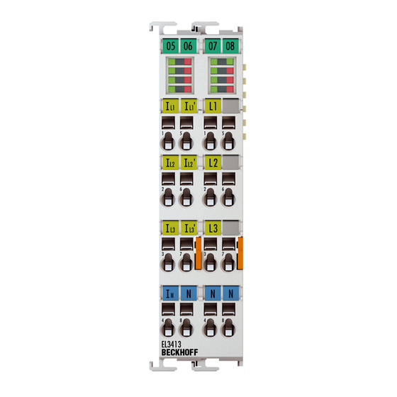
Installation 4.7.3 EL3413-0120 Fig. 40: EL3413-0120 LEDs LEDs Color Meaning green This LED indicates the terminal's operating state: State of the EtherCAT State Machine [} 30]: INIT = initialization of the terminal or fast flashing State of the EtherCAT State Machine [} 30]: BOOTSTRAP = function for firmware updates [} 184] of the terminal flashing State of the EtherCAT State Machine [} 30]:... -
Page 57: Fig. 41 El3413-0120 Connection
Installation Connection Fig. 41: EL3413-0120 Connection WARNING Do not operate current transformers in no-load mode! Please note that many manufacturers do not permit their current transformers to be operated in no-load mode! Connect the EL3413 to the secondary windings of the current transformers before using the current transformer! Terminal point Description... - Page 58 Installation Terminal point Description Name Phase L1 voltage measurement input Phase L2 voltage measurement input Phase L3 voltage measurement input Neutral conductor n.c. n.c. n.c. Neutral conductor Version: 4.4 EL34x3...
-
Page 59: El3433-0000
Installation 4.7.4 EL3433-0000 Fig. 42: EL3433-0000 LEDs LEDs Color Meaning green This LED indicates the terminal's operating state: State of the EtherCAT State Machine [} 30]: INIT = initialization of the terminal or fast flashing State of the EtherCAT State Machine [} 30]: BOOTSTRAP = function for firmware updates [} 184] of the terminal flashing State of the EtherCAT State Machine [} 30]:... - Page 60 Installation Connection Fig. 43: EL3433-0000 Connection WARNING Do not operate current transformers in no-load mode! Please note that many manufacturers do not permit their current transformers to be operated in no-load mode! Connect the EL3413 to the secondary windings of the current transformers before using the current transformer! Terminal point Description...
- Page 61 Installation Terminal point Description Name Phase L1 voltage measurement output Phase L2 voltage measurement output Phase L3 voltage measurement output Neutral conductor Phase L1 voltage measurement input Phase L2 voltage measurement input Phase L3 voltage measurement input Neutral conductor EL34x3 Version: 4.4...
-
Page 62: Commissioning
• "offline": The configuration can be customized by adding and positioning individual components. These can be selected from a directory and configured. ◦ The procedure for offline mode can be found under http://infosys.beckhoff.com: TwinCAT 2 → TwinCAT System Manager → IO - Configuration → Adding an I/O Device •... - Page 63 Commissioning Fig. 44: Relationship between user side (commissioning) and installation The user inserting of certain components (I/O device, terminal, box...) is the same in TwinCAT 2 and TwinCAT 3. The descriptions below relate to the online procedure. Sample configuration (actual configuration) Based on the following sample configuration, the subsequent subsections describe the procedure for TwinCAT 2 and TwinCAT 3: •...
- Page 64 Commissioning Fig. 45: Control configuration with Embedded PC, input (EL1004) and output (EL2008) Note that all combinations of a configuration are possible; for example, the EL1004 terminal could also be connected after the coupler, or the EL2008 terminal could additionally be connected to the CX2040 on the right, in which case the EK1100 coupler wouldn’t be necessary.
- Page 65 Commissioning 5.1.1 TwinCAT 2 Startup TwinCAT basically uses two user interfaces: the TwinCAT System Manager for communication with the electromechanical components and TwinCAT PLC Control for the development and compilation of a controller. The starting point is the TwinCAT System Manager. After successful installation of the TwinCAT system on the PC to be used for development, the TwinCAT 2 System Manager displays the following user interface after startup: Fig. 46: Initial TwinCAT 2 user interface...
- Page 66 Commissioning Fig. 47: Selection of the target system Use "Search (Ethernet)..." to enter the target system. Thus a next dialog opens to either: • enter the known computer name after "Enter Host Name / IP:" (as shown in red) • perform a "Broadcast Search" (if the exact computer name is not known) •...
- Page 67 Commissioning Adding devices In the configuration tree of the TwinCAT 2 System Manager user interface on the left, select "I/O Devices” and then right-click to open a context menu and select "Scan Devices…", or start the action in the menu bar . The TwinCAT System Manager may first have to be set to "Config mode" via or via menu “Actions"...
- Page 68 Commissioning Fig. 51: Mapping of the configuration in the TwinCAT 2 System Manager The whole process consists of two stages, which may be performed separately (first determine the devices, then determine the connected elements such as boxes, terminals, etc.). A scan can also be initiated by selecting "Device ..."...
- Page 69 Commissioning ◦ Structured Text (ST) • Graphical languages ◦ Function Block Diagram (FBD) ◦ Ladder Diagram (LD) ◦ The Continuous Function Chart Editor (CFC) ◦ Sequential Function Chart (SFC) The following section refers to Structured Text (ST). After starting TwinCAT PLC Control, the following user interface is shown for an initial project: Fig. 53: TwinCAT PLC Control after startup Sample variables and a sample program have been created and stored under the name "PLC_example.pro": EL34x3...
- Page 70 Commissioning Fig. 54: Sample program with variables after a compile process (without variable integration) Warning 1990 (missing "VAR_CONFIG") after a compile process indicates that the variables defined as external (with the ID "AT%I*" or "AT%Q*") have not been assigned. After successful compilation, TwinCAT PLC Control creates a "*.tpy"...
- Page 71 Commissioning Select the PLC configuration "PLC_example.tpy" in the browser window that opens. The project including the two variables identified with "AT" are then integrated in the configuration tree of the System Manager: Fig. 56: PLC project integrated in the PLC configuration of the System Manager The two variables "bEL1004_Ch4"...
- Page 72 Commissioning Fig. 58: Selecting PDO of type BOOL According to the default setting, certain PDO objects are now available for selection. In this sample the input of channel 4 of the EL1004 terminal is selected for linking. In contrast, the checkbox "All types" must be ticked for creating the link for the output variables, in order to allocate a set of eight separate output bits to a byte variable.
- Page 73 Commissioning Fig. 60: Application of a "Goto Link" variable, using "MAIN.bEL1004_Ch4" as a sample The process of assigning variables to the PDO is completed via the menu selection "Actions" → "Generate Mappings”, key Ctrl+M or by clicking on the symbol in the menu. This can be visualized in the configuration: The process of creating links can also take place in the opposite direction, i.e.
- Page 74 Commissioning Fig. 61: Choose target system (remote) In this sample "Runtime system 1 (port 801)" is selected and confirmed. Link the PLC with the real-time system via menu option "Online" → "Login", the F11 key or by clicking on the symbol . The control program can then be loaded for execution.
- Page 75 Commissioning Fig. 62: PLC Control logged in, ready for program startup The PLC can now be started via "Online" → "Run", F5 key or 5.1.2 TwinCAT 3 Startup TwinCAT makes the development environment areas available together with Microsoft Visual Studio: after startup, the project folder explorer appears on the left in the general window area (cf.
- Page 76 Commissioning Fig. 63: Initial TwinCAT 3 user interface First create a new project via (or under "File"→“New"→ "Project…"). In the following dialog make the corresponding entries as required (as shown in the diagram): Fig. 64: Create new TwinCAT project The new project is then available in the project folder explorer: Version: 4.4 EL34x3...
- Page 77 Commissioning Fig. 65: New TwinCAT3 project in the project folder explorer Generally, TwinCAT can be used in local or remote mode. Once the TwinCAT system including the user interface (standard) is installed on the respective PLC, TwinCAT can be used in local mode and thereby the next step is "Insert Device [} 78]".
- Page 78 Commissioning Use "Search (Ethernet)..." to enter the target system. Thus a next dialog opens to either: • enter the known computer name after "Enter Host Name / IP:" (as shown in red) • perform a "Broadcast Search" (if the exact computer name is not known) •...
- Page 79 Commissioning Fig. 69: Automatic detection of I/O devices: selection the devices to be integrated Confirm the message "Find new boxes", in order to determine the terminals connected to the devices. "Free Run" enables manipulation of input and output values in "Config mode" and should also be acknowledged. Based on the sample configuration [} 63] described at the beginning of this section, the result is as follows: Fig. 70: Mapping of the configuration in VS shell of the TwinCAT3 environment The whole process consists of two stages, which may be performed separately (first determine the devices,...
- Page 80 Commissioning Fig. 71: Reading of individual terminals connected to a device This functionality is useful if the actual configuration is modified at short notice. Programming the PLC TwinCAT PLC Control is the development environment for the creation of the controller in different program environments: TwinCAT PLC Control supports all languages described in IEC 61131-3.
- Page 81 Commissioning Fig. 72: Adding the programming environment in "PLC" In the dialog that opens select "Standard PLC project" and enter "PLC_example" as project name, for example, and select a corresponding directory: Fig. 73: Specifying the name and directory for the PLC programming environment The "Main"...
- Page 82 Commissioning Fig. 74: Initial "Main" program of the standard PLC project To continue, sample variables and a sample program have now been created: Version: 4.4 EL34x3...
- Page 83 Commissioning Fig. 75: Sample program with variables after a compile process (without variable integration) The control program is now created as a project folder, followed by the compile process: Fig. 76: Start program compilation The following variables, identified in the ST/ PLC program with "AT%", are then available in under "Assignments"...
- Page 84 Commissioning Fig. 77: Creating the links between PLC variables and process objects In the window that opens, the process object for the variable "bEL1004_Ch4" of type BOOL can be selected from the PLC configuration tree: Fig. 78: Selecting PDO of type BOOL According to the default setting, certain PDO objects are now available for selection.
- Page 85 Commissioning Fig. 79: Selecting several PDOs simultaneously: activate "Continuous" and "All types" Note that the "Continuous" checkbox was also activated. This is designed to allocate the bits contained in the byte of the variable "nEL2008_value" sequentially to all eight selected output bits of the EL2008 terminal. In this way it is possible to subsequently address all eight outputs of the terminal in the program with a byte corresponding to bit 0 for channel 1 to bit 7 for channel 8 of the PLC.
- Page 86 Commissioning Activation of the configuration The allocation of PDO to PLC variables has now established the connection from the controller to the inputs and outputs of the terminals. The configuration can now be activated with or via the menu under "TwinCAT"...
-
Page 87: Twincat 2
5.2.1 Installation of the TwinCAT real-time driver In order to assign real-time capability to a standard Ethernet port of an IPC controller, the Beckhoff real-time driver has to be installed on this port under Windows. This can be done in several ways. One option is described here. - Page 88 Commissioning Fig. 82: System Manager “Options” (TwinCAT 2) This have to be called up by the Menü “TwinCAT” within the TwinCAT 3 environment: Fig. 83: Call up under VS Shell (TwinCAT 3) The following dialog appears: Fig. 84: Overview of network interfaces Interfaces listed under “Compatible devices” can be assigned a driver via the “Install” button. A driver should only be installed on compatible devices.
- Page 89 Commissioning Fig. 85: EtherCAT device properties(TwinCAT 2): click on „Compatible Devices…“ of tab “Adapter” TwinCAT 3: the properties of the EtherCAT device can be opened by double click on “Device .. (EtherCAT)” within the Solution Explorer under “I/O”: After the installation the driver appears activated in the Windows overview for the network interface (Windows Start →...
- Page 90 Commissioning Fig. 87: Exemplary correct driver setting for the Ethernet port Other possible settings have to be avoided: Version: 4.4 EL34x3...
- Page 91 Commissioning Fig. 88: Incorrect driver settings for the Ethernet port EL34x3 Version: 4.4...
- Page 92 Commissioning IP address of the port used IP address/DHCP In most cases an Ethernet port that is configured as an EtherCAT device will not transport general IP packets. For this reason and in cases where an EL6601 or similar devices are used it is useful to specify a fixed IP address for this port via the “Internet Protocol TCP/IP”...
-
Page 93: Notes Regarding Esi Device Description
The files are read (once) when a new System Manager window is opened, if they have changed since the last time the System Manager window was opened. A TwinCAT installation includes the set of Beckhoff ESI files that was current at the time when the TwinCAT build was created. - Page 94 1018 in the configuration. This is also stated by the Beckhoff compatibility rule. Refer in particular to the chapter ‘General notes on the use of Beckhoff EtherCAT IO components’ and for manual configuration to the chapter ‘Offline configuration creation’ [} 98].
- Page 95 Commissioning Fig. 93: File OnlineDescription.xml created by the System Manager Is a slave desired to be added manually to the configuration at a later stage, online created slaves are indicated by a prepended symbol “>” in the selection list (see Figure “Indication of an online recorded ESI of EL2521 as an example”).
- Page 96 Commissioning Reasons may include: • Structure of the *.xml does not correspond to the associated *.xsd file → check your schematics • Contents cannot be translated into a device description → contact the file manufacturer Version: 4.4 EL34x3...
-
Page 97: Twincat Esi Updater
Commissioning 5.2.3 TwinCAT ESI Updater For TwinCAT 2.11 and higher, the System Manager can search for current Beckhoff ESI files automatically, if an online connection is available: Fig. 96: Using the ESI Updater (>= TwinCAT 2.11) The call up takes place under: “Options” → "Update EtherCAT Device Descriptions"... -
Page 98: Offline Configuration Creation
Commissioning • the devices/modules be connected to the power supply and ready for communication • TwinCAT must be in CONFIG mode on the target system. The online scan process consists of: • detecting the EtherCAT device [} 103] (Ethernet port at the IPC) •... - Page 99 Commissioning This query may appear automatically when the EtherCAT device is created, or the assignment can be set/ modified later in the properties dialog; see Fig. “EtherCAT device properties (TwinCAT 2)”. Fig. 101: EtherCAT device properties (TwinCAT 2) TwinCAT 3: the properties of the EtherCAT device can be opened by double click on “Device .. (EtherCAT)” within the Solution Explorer under “I/O”: Selecting the Ethernet port Ethernet ports can only be selected for EtherCAT devices for which the TwinCAT real-time driver is...
- Page 100 (i.e. highest) revision and therefore the latest state of production is displayed in the selection dialog for Beckhoff devices. To show all device revisions available in the system as ESI descriptions tick the “Show Hidden Devices” check box, see Fig. “Display of previous revisions”.
- Page 101 If current ESI descriptions are available in the TwinCAT system, the last revision offered in the selection dialog matches the Beckhoff state of production. It is recommended to use the last device revision when creating a new configuration, if current Beckhoff devices are used in the real application. Older revisions should only be used if older devices from stock are to be used in the application.
- Page 102 Commissioning Fig. 107: EtherCAT terminal in the TwinCAT tree (left: TwinCAT 2; right: TwinCAT 3) Version: 4.4 EL34x3...
-
Page 103: Online Configuration Creation
Commissioning 5.2.6 ONLINE configuration creation Detecting/scanning of the EtherCAT device The online device search can be used if the TwinCAT system is in CONFIG mode. This can be indicated by a symbol right below in the information bar: • on TwinCAT 2 by a blue display “Config Mode” within the System Manager window: •... - Page 104 [} 108] with the defined initial configuration.Background: since Beckhoff occasionally increases the revision version of the delivered products for product maintenance reasons, a configuration can be created by such a scan which (with an identical machine construction) is identical according to the device list;...
- Page 105 Likewise, A might create spare parts stores worldwide for the coming series-produced machines with EL2521-0025-1018 terminals. After some time Beckhoff extends the EL2521-0025 by a new feature C. Therefore the FW is changed, outwardly recognizable by a higher FW version and a new revision -1019. Nevertheless the new device naturally supports functions and interfaces of the predecessor version(s);...
- Page 106 Commissioning Fig. 116: Manual triggering of a device scan on a specified EtherCAT device (left: TwinCAT 2; right: TwinCAT 3) In the System Manager (TwinCAT 2) or the User Interface (TwinCAT 3) the scan process can be monitored via the progress bar at the bottom in the status bar. Fig. 117: Scan progressexemplary by TwinCAT 2 The configuration is established and can then be switched to online state (OPERATIONAL).
- Page 107 Commissioning Fig. 121: Online display example Please note: • all slaves should be in OP state • the EtherCAT master should be in “Actual State” OP • “frames/sec” should match the cycle time taking into account the sent number of frames •...
- Page 108 A ‘ChangeTo’ or ‘Copy’ should only be carried out with care, taking into consideration the Beckhoff IO compatibility rule (see above). The device configuration is then replaced by the revision found; this can affect the supported process data and functions.
- Page 109 If current ESI descriptions are available in the TwinCAT system, the last revision offered in the selection dialog matches the Beckhoff state of production. It is recommended to use the last device revision when creating a new configuration, if current Beckhoff devices are used in the real application. Older revisions should only be used if older devices from stock are to be used in the application.
- Page 110 Commissioning Fig. 126: Correction dialog with modifications Once all modifications have been saved or accepted, click “OK” to transfer them to the real *.tsm configuration. Change to Compatible Type TwinCAT offers a function “Change to Compatible Type…” for the exchange of a device whilst retaining the links in the task.
-
Page 111: Ethercat Subscriber Configuration
Commissioning If called, the System Manager searches in the procured device ESI (in this example: EL1202-0000) for details of compatible devices contained there. The configuration is changed and the ESI-EEPROM is overwritten at the same time – therefore this process is possible only in the online state (ConfigMode). 5.2.7 EtherCAT subscriber configuration In the left-hand window of the TwinCAT 2 System Manager or the Solution Explorer of the TwinCAT 3... - Page 112 Commissioning „EtherCAT“ tab Fig. 131: „EtherCAT“ tab Type EtherCAT device type Product/Revision Product and revision number of the EtherCAT device Auto Inc Addr. Auto increment address of the EtherCAT device. The auto increment address can be used for addressing each EtherCAT device in the communication ring through its physical position.
- Page 113 For Beckhoff EtherCAT EL, ES, EM, EJ and EP slaves the following applies in general: • The input/output process data supported by the device are defined by the manufacturer in the ESI/XML description.
- Page 114 Commissioning Fig. 133: Configuring the process data Manual modification of the process data According to the ESI description, a PDO can be identified as “fixed” with the flag “F” in the PDO overview (Fig. “Configuring the process data”, J). The configuration of such PDOs cannot be changed, even if TwinCAT offers the associated dialog (“Edit”).
- Page 115 Commissioning Fig. 134: „Startup“ tab Column Description Transition Transition to which the request is sent. This can either be • the transition from pre-operational to safe-operational (PS), or • the transition from safe-operational to operational (SO). If the transition is enclosed in "<>" (e.g. <PS>), the mailbox request is fixed and cannot be modified or deleted by the user.
- Page 116 Commissioning Fig. 135: “CoE – Online” tab Object list display Column Description Index Index and sub-index of the object Name Name of the object Flags The object can be read, and data can be written to the object (read/write) The object can be read, but no data can be written to the object (read only) An additional P identifies the object as a process data object.
- Page 117 Commissioning Fig. 136: Dialog “Advanced settings” Online - via SDO Information If this option button is selected, the list of the objects included in the object list of the slave is uploaded from the slave via SDO information. The list below can be used to specify which object types are to be uploaded. Offline - via EDS File If this option button is selected, the list of the objects included in the object list is read from an EDS file provided by the user.
- Page 118 Fig. 138: "DC" tab (Distributed Clocks) Operation Mode Options (optional): • FreeRun • SM-Synchron • DC-Synchron (Input based) • DC-Synchron Advanced Settings… Advanced settings for readjustment of the real time determinant TwinCAT- clock Detailed information to Distributed Clocks are specified on http://infosys.beckhoff.com: Version: 4.4 EL34x3...
- Page 119 Commissioning Fieldbus Components → EtherCAT Terminals → EtherCAT System documentation → EtherCAT basics → Distributed Clocks 5.2.7.1 Detailed description of Process Data tab Sync Manager Lists the configuration of the Sync Manager (SM). If the EtherCAT device has a mailbox, SM0 is used for the mailbox output (MbxOut) and SM1 for the mailbox input (MbxIn).
-
Page 120: General Notes - Ethercat Slave Application
Commissioning PDO Content Indicates the content of the PDO. If flag F (fixed content) of the PDO is not set the content can be modified. Download If the device is intelligent and has a mailbox, the configuration of the PDO and the PDO assignments can be downloaded to the device. - Page 121 Fig. “Basic EtherCAT Slave Diagnosis in the PLC” shows an example of an implementation of basic EtherCAT Slave Diagnosis. A Beckhoff EL3102 (2-channel analogue input terminal) is used here, as it offers both the communication diagnosis typical of a slave and the functional diagnosis that is specific to a channel.
- Page 122 Commissioning The following aspects are covered here: Code Function Implementation Application/evaluation The EtherCAT Master's diagnostic infor- At least the DevState is to be evaluated for mation the most recent cycle in the PLC. updated acyclically (yellow) or provided The EtherCAT Master's diagnostic informa- acyclically (green).
- Page 123 Commissioning Fig. 141: EL3102, CoE directory EtherCAT System Documentation The comprehensive description in the EtherCAT System Documentation (EtherCAT Basics --> CoE Interface) must be observed! A few brief extracts: • Whether changes in the online directory are saved locally in the slave depends on the device. EL terminals (except the EL66xx) are able to save in this way.
- Page 124 Commissioning Fig. 142: Example of commissioning aid for a EL3204 This commissioning process simultaneously manages • CoE Parameter Directory • DC/FreeRun mode • the available process data records (PDO) Although the "Process Data", "DC", "Startup" and "CoE-Online" that used to be necessary for this are still displayed, it is recommended that, if the commissioning aid is used, the automatically generated settings are not changed by it.
- Page 125 Commissioning Standard setting The advanced settings of the EtherCAT Master are set as standard: • EtherCAT Master: OP • Slaves: OP This setting applies equally to all Slaves. Fig. 143: Default behaviour of the System Manager In addition, the target state of any particular Slave can be set in the "Advanced Settings" dialogue; the standard setting is again OP.
- Page 126 Commissioning Manual Control There are particular reasons why it may be appropriate to control the states from the application/task/PLC. For instance: • for diagnostic reasons • to induce a controlled restart of axes • because a change in the times involved in starting is desirable In that case it is appropriate in the PLC application to use the PLC function blocks from the TcEtherCAT.lib, which is available as standard, and to work through the states in a controlled manner using, for instance, FB_EcSetMasterState.
- Page 127 Commissioning Fig. 146: Illegally exceeding the E-Bus current From TwinCAT 2.11 and above, a warning message "E-Bus Power of Terminal..." is output in the logger window when such a configuration is activated: Fig. 147: Warning message for exceeding E-Bus current NOTE Caution! Malfunction possible! The same ground potential must be used for the E-Bus supply of all EtherCAT terminals in a terminal block! EL34x3 Version: 4.4...
-
Page 128: Process Data
Commissioning Process data 5.4.1 Sync Manager (SM) The scope of the offered process data can be viewed on the “Process data” tab in the TwinCAT System Manager (see fig. Process data tab SM2, EL34x3 + Process data tab SM3, EL34x3). Fig. 148: Process Data tab SM2, EL34x3 Version: 4.4 EL34x3... - Page 129 Commissioning Fig. 149: Process Data tab SM3, EL34x3 PDO Assignment SM2, PDO assignment 0x1C12 Index Index of Size Name PDO content excluded (Byte. PDOs Bit) 0x1600 Index 0x7000:01 [} 163] - Index (default) Outputs Channel 1 0x1601(d Index 0x7010:01 [} 163] - Index efault) Outputs Channel 2...
- Page 130 Commissioning SM3, PDO Assignment 0x1C13 Index Index of Size Name PDO content excluded (Byte. PDOs Bit) 0x1A00 20.0 PM Inputs Index 0x6000:01 [} 158] - STATUS_Overvoltage (default) Channel 1 Index 0x6000:02 [} 158] - STATUS_Undervoltage Index 0x6000:03 [} 158] - STATUS_Overcurrent Index 0x6000:05 [} 159] - STATUS_Phase sequence cw Index 0x6000:06 [} 158] - STATUS_Phase sequence ccw Index 0x6000:07 [} 158] - STATUS_Missing zero crossing Index 0x6000:0F - STATUS_TxPDO State...
-
Page 131: Operating Modes And Settings
Commissioning 5.4.2 Operating modes and settings Confirmation of the variable output value, channel 1 - 3 (PDOs: PM inputs Channel 1 – 3, subindex “Index” [0x6000:14 [} 158], 0x6010:14 [} 159], 0x6020:14 [} 160]]) The calculated values can be output on the PDOs: PM Inputs Channel 1 - 3, subindex “Variant value” [0x6000:1D [} 158], 0x6010:1D [} 159], 0x6020:1D [} 160]] (see object description [} 158]). - Page 132 Commissioning Values (dec), Values (dec), entry Name Unit entry in index in index 0x7030:01 0x7030:02 Neutral conductor current 0.000001 A Sum of the energy (channel 1-3) 0.001 Wh Frequency 0.1 Hz Sum of the energy (negative) (channel 1-3) 0.001 Wh Sum of the active power (channel 1-3) 0.01 W Sum of the apparent power (channel 1-3) 0.01 VA...
-
Page 133: Predefined Pdo Assignment
Commissioning 5.4.3 Predefined PDO Assignment The "Predefined PDO Assignment" enables a simplified selection of the process data. The desired function is selected on the lower part of the "Process Data" tab. As a result, all necessary PDOs are automatically activated and the unnecessary PDOs are deactivated. If channels are not to be used, it is recommended to deactivate the respective channels in order to avoid possible error messages from the terminal. - Page 134 Commissioning 5.5.1.1 Reference channel for the frequency measurement and power/energy measurement In the EL34x3 all 3 channels are always selected independently of one another as reference for the frequency measurement or power/energy measurement. In order to avoid an error message from the terminal, the channels that are not in use should be deactivated.
-
Page 135: Measurements
Commissioning 5.5.1.4 PM Command (Index 0xFB00) The command object is used for triggering an action in the terminal. The command is started by writing subindex 1 (request). Write access is disabled until the current command is completed. When writing the subindex, note that you cannot write directly in the "Hex" field; the "Binary" field must be used for this. - Page 136 Commissioning 5.5.2.1 Energy Name Index Variant Value AUX channel Sum (Ch 0) Channel ac- 0x90n0 0xF801 cess (Ch 11/12/13) Energy |E+| - |E-| ∑ |E+| - ∑ |E-| |E+| - |E-| difference Energy -|E-| ∑ |E-| |E-| |E-| |E-| negative Energy |E+| ∑...
- Page 137 Commissioning Sample 2 To delete the energy values of all channels manually enter 0024 in index 0xFB00:01 [} 153]. 5.5.2.2 PM Inputs Channel 1/2/3 STATUS The following useful status information for the respective channel can be read in with the “STATUS” structure.
- Page 138 Commissioning Redundant checking of the mains frequency for system control is recommended. The EL34x3 terminals are power measurement terminals. The mains frequency is measured and displayed, but it should not be used as the sole value to control systems. In particular, step changes in the mains frequency can influence the frequency measurement and produce implausible values.
-
Page 139: Scaling Factors
Commissioning • the current • the voltage • the active power • the power factor cos φ Switching of the individual parameters takes place using the cyclic "Index" output variables (see also tables in chapter “Operating modes and settings” [} 131]). 5.5.2.4 PM Outputs Channel 1/2/3 Index... -
Page 140: Notices On Analog Specifications
(EL3413 = 5 A and EL3433 = 10 A) and cannot be switched. Notices on analog specifications Beckhoff I/O devices (terminals, boxes, modules) with analog inputs are characterized by a number of technical characteristic data; refer to the technical data in the respective documents. -
Page 141: Full Scale Value (Fsv)
For analog I/O devices from Beckhoff the rule is that the limit with the largest value is chosen as the full scale value of the respective product (also called the reference value) and is given a positive sign. This applies to both symmetrical and asymmetrical measuring spans. -
Page 142: Temperature Coefficient Tk [Ppm/K]
A manufacturer can alleviate this by using components of a higher quality or by software means. The temperature coefficient, when indicated, specified by Beckhoff allows the user to calculate the expected measuring error outside the basic accuracy at 23 °C. -
Page 143: Single-Ended/Differential Typification
In particular this also applies to SE, even though the term suggest that only one wire is required. • The term "electrical isolation" should be clarified in advance. Beckhoff IO modules feature 1..8 or more analog channels; with regard to the channel connection a distinction is made in terms of: ◦... - Page 144 The property of electrical isolation indicates whether the channels are directly connected to each other. ◦ Beckhoff terminals/ boxes (and related product groups) always feature electrical isolation between the field/analog side and the bus/EtherCAT side. In other words, if two analog terminals/ boxes are not connected via the power contacts (cable), the modules are effectively electrically isolated.
- Page 145 +signal can be connected to +supply or –signal to –supply. - Yes: then you can connect accordingly to a Beckhoff ‘single-ended’ input. - No: the Beckhoff ‘differential’ input for +Signal and –Signal is to be selected; +Supply and – Supply are to be connected via additional cables.
- Page 146 Commissioning Fig. 155: Connection of externally supplied sensors Classification of the Beckhoff terminals/ boxes - Beckhoff 0/4-20 mA terminals/ boxes (and related product groups) are available as differential and single-ended terminals/ boxes (and related product groups): Single-ended Differential EL3x4x: 0-20 mA, EL3x5x: 4-20 mA; KL and related product EL3x1x: 0-20 mA, EL3x2x: 4-20 mA;...
- Page 147 Commissioning Single-ended Differential Fig. 156: 2-, 3- and 4-wire connection at single-ended and differential inputs EL34x3 Version: 4.4...
-
Page 148: Common-Mode Voltage And Reference Ground (Based On Differential Inputs)
Reference ground samples for Beckhoff IO devices: 1. Internal AGND fed out: EL3102/EL3112, resistive connection between the channels 2. 0V power contact: EL3104/EL3114, resistive connection between the channels and AGND; AGND connected to 0V power contact with low-resistance 3. -
Page 149: Temporal Aspects Of Analog/Digital Conversion
The conversion of the constant electrical input signal to a value-discrete digital and machine-readable form takes place in the analog Beckhoff EL/KL/EP input modules with ADC (analog digital converter). Although different ADC technologies are in use, from a user perspective they all have a common characteristic: after the conversion a certain digital value is available in the controller for further processing. - Page 150 This is the “external” view of the “Beckhoff AI channel” system – internally the signal delay in particular is composed of different components: hardware, amplifier, conversion itself, data transport and processing.
- Page 151 Commissioning Fig. 160: Diagram signal delay (step response) 2.2 Signal delay (linear) Keyword: Group delay Describes the delay of a signal with constant frequency A test signal can be generated externally with a frequency generator, e.g. as sawtooth or sine. A simultaneous square wave signal would be used as reference.
-
Page 152: Object Description And Parameterization
EtherCAT XML Device Description The display matches that of the CoE objects from the EtherCAT XML Device Description. We rec- ommend downloading the latest XML file from the download area of the Beckhoff website and in- stalling it according to installation instructions. -
Page 153: Configuration Data
Commissioning 5.7.2 Configuration data Index 8027 PM Settings Index (hex) Name Meaning Data type Flags Default 8027:0 PM Settings Value Description UINT8 >40< 8027:03 Measuring Measuring method 3-wire connection delta, 4- BIT2 0x00 (0 mode wire connection star reserved reserved 8027:19* Current range Current measuring 1 A... - Page 154 Commissioning Index (hex) Name Meaning Data type Flags Default FB00:0 PM Command Largest subindex of this object UINT8 >3< FB00:01 Request Byte 0 - service request data OCTET- 0x0000 (0 STRING[2] Switch off measurement of the phase Clear energy [} 135] Switch on phase Save energy [} 135] Change measuring interval [} 133]...
-
Page 155: Configuration Data (Vendor-Specific)
Commissioning 5.7.4 Configuration data (vendor-specific) Index 800F PM Vendor data Ch.1 Index (hex) Name Meaning Data type Flags Default 800F:0 PM Vendor data Ch.1 Largest subindex of this object UINT8 >34< 800F:02 EL3413-xxxx: Vendor calibration EL3413-xxxx: UINT16 0x4000 Calibration current Gain current measuring range, 1 A, channel 1 (16384 gain (1 A) - Page 156 Commissioning Index 801F PM Vendor data Ch.2 Index (hex) Name Meaning Data type Flags Default 801F:0 PM Vendor data Ch.2 Largest subindex of this object UINT8 >34< 801F:02 EL3413-xxxx: Vendor calibration EL3413-xxxx: UINT16 0x4000 Calibration current Gain current measuring range, 1 A, channel 2 (16384 gain (1 A) EL3433-xxxx:...
- Page 157 Commissioning Index 802F PM Vendor data Ch.3 Index (hex) Name Meaning Data type Flags Default 802F:0 PM Vendor data Ch.3 Largest subindex of this object UINT8 >34< 802F:02 EL3413-xxxx: Vendor calibration EL3413-xxxx: UINT16 0x4000 Calibration current Gain current measuring range, 1 A, channel 3 (16384 gain (1 A) EL3433-xxxx:...
-
Page 158: Input Data
Commissioning 5.7.5 Input data Index 6000 PM Inputs Ch.1 Index (hex) Name Meaning Data type Flags Default 6000:0 PM Inputs Ch.1 Largest subindex of this object UINT8 >29< 6000:01 Overvoltage Overvoltage detected BOOLEAN 0x00 (0 EL3413-0000: > 415 V (L1-N) EL3413-0001: > 360 V (L1-N) EL3413-0120: >... - Page 159 Commissioning ***) for EL3413 from firmware 08, EL3413-0120 from firmware 04, EL3413-0001/EL3433 from firmware 10 ****) from firmware 10 Index 6010 PM Inputs Ch.2 Index (hex) Name Meaning Data type Flags Default 6010:0 PM Inputs Ch.2 Largest subindex of this object UINT8 >29<...
- Page 160 Commissioning ***) for EL3413 from firmware 08, EL3413-120 from firmware 04, EL3413-1/EL3433 from firmware 10 ****) from firmware 10 Index 6020 PM Inputs Ch.3 Index (hex) Name Meaning Data type Flags Default 6020:0 PM Inputs Ch.3 Largest subindex of this object UINT8 >29<...
- Page 161 Commissioning ***) for EL3413 from firmware 08, EL3413-120 from firmware 04, EL3413-1/EL3433 from firmware 10 ****) from firmware 10 EL34x3 Version: 4.4...
- Page 162 Commissioning Index 6030 PM Inputs Auxiliary Index (hex) Name Meaning Data type Flags Default 6030:0 PM Inputs Ch.3 Largest subindex of this object UINT8 >19< 6030:03 Overcurrent Overcurrent BOOLEAN 0x00 (0 6030:0F TxPDO State TRUE for general error BOOLEAN 0x00 (0 6030:10 TxPDO Toggle The TxPDO toggle is toggled by the slave when the data...
-
Page 163: Output Data
Commissioning ***) for EL3413 from firmware 08, EL3413-0120 from firmware 04, EL3413-1/EL3433 from firmware 10 ****) from firmware 10 Calculation of harmonics It is not possible to calculate harmonics for more than one channel at the same time. Index 00 or 100 is returned until the harmonic calculation has been completed. - Page 164 Commissioning Index F010 Module list Index (hex) Name Meaning Data type Flags Default F010:0 Module list Largest subindex of this object UINT8 >4< F010:01 Subindex 001 MDP Profile 340 UINT32 0x00000154 (340 F010:02 Subindex 002 MDP Profile 340 UINT32 0x00000154 (340 F010:03 Subindex 003...
-
Page 165: Standard Objects
Commissioning 5.7.8 Standard objects The standard objects have the same meaning for all EtherCAT slaves. Index 1000 Device type Index (hex) Name Meaning Data type Flags Default 1000:0 Device type Device type of the EtherCAT slave: the Lo-Word contains UINT32 0x00001389 the profile used (5001). - Page 166 Commissioning Index 10F8 Actual Time Stamp Index (hex) Name Meaning Data type Flags Default 10F8:0 Actual Time Stamp Time stamp UINT64 Index 1600 RxPDO-Map Ch.1 Index (hex) Name Meaning Data type Flags Default 1600:0 RxPDO-Map Ch.1 PDO mapping of RxPDO 1 UINT8 >1<...
- Page 167 Commissioning Index 1A00 TxPDO-Map Ch.1 Index (hex) Name Meaning Data type Flags Default 1A00:0 TxPDO-Map Ch.1 PDO Mapping of TxPDO 1 UINT8 >16< 1A00:01 SubIndex 001 1. PDO Mapping entry (object 0x6000 (PM Inputs Ch.1), UINT32 0x6000:01, 1 entry 0x01 (Undervoltage)) 1A00:02 SubIndex 002 2.
- Page 168 Commissioning Index 1A01 TxPDO-Map Ch.2 Index (hex) Name Meaning Data type Flags Default 1A01:0 TxPDO-Map Ch.2 PDO Mapping of TxPDO 2 UINT8 >16< 1A01:01 SubIndex 001 1. PDO Mapping entry (object 0x6010 (PM Inputs Ch.1), UINT32 0x6010:01, 1 entry 0x01 (Undervoltage)) 1A01:02 SubIndex 002 2.
- Page 169 Commissioning Index 1A02 TxPDO-Map Ch.3 Index (hex) Name Meaning Data type Flags Default 1A02:0 TxPDO-Map Ch.3 PDO Mapping of TxPDO 3 UINT8 >16< 1A02:01 SubIndex 001 1. PDO Mapping entry (object 0x6020 (PM Inputs Ch.1), UINT32 0x6020:01, 1 entry 0x01 (Undervoltage)) 1A02:02 SubIndex 002 2.
- Page 170 Commissioning Index 1C12 RxPDO assign Index (hex) Name Meaning Data type Flags Default 1C12:0 RxPDO assign PDO Assign of the Outputs UINT8 >4< 1C32:01 Subindex 001 1. assigned PDO (RxPDO-Map Ch.1 (RxPDO 1)) UINT16 0x1600 (5632 1C12:02 Subindex 002 2. assigned PDO (RxPDO-Map Ch.2 (RxPDO 2)) UINT16 0x1601 (5633...
- Page 171 Commissioning Index 1C32 SM output parameter Index (hex) Name Meaning Data type Flags Default 1C32:0 SM output parameter Synchronization parameters for the outputs UINT8 >32< 1C32:01 Sync mode Current synchronization mode: UINT16 0x0000 (0 • 0: Free Run • 1: Synchron with SM 2 Event •...
- Page 172 Commissioning Index 1C33 SM input parameter Index (hex) Name Meaning Data type Flags Default 1C33:0 SM input parameter Synchronization parameters for the inputs UINT8 >32< 1C33:01 Sync mode Current synchronization mode: UINT16 0x0000 (0 • 0: Free Run • 1: Synchron with SM 3 event (no outputs available) •...
-
Page 173: Diagnostics - Basic Principles Of Diag Messages
The DiagMessages are explained in text form in the ESI/XML file belonging to the EtherCAT device: on the basis of the Text ID contained in the DiagMessage, the corresponding plain text message can be found in the languages contained in the ESI/XML. In the case of Beckhoff products these are usually German and English. - Page 174 DC slave. Structure of the Text ID The structure of the MessageID is not subject to any standardization and can be supplier-specifically defined. In the case of Beckhoff EtherCAT devices (EL, EP) it usually reads according to xyzz: Version: 4.4 EL34x3...
- Page 175 Diagnostics – basic principles of diag messages 0: Systeminfo 0: System Error number 2: reserved 1: General 1: Info 2: Communication 4: Warning 3: Encoder 8: Error 4: Drive 5: Inputs 6: I/O general 7: reserved Example: Message 0x4413 --> Drive Warning Number 0x13 Overview of text IDs Specific Text IDs should be specified in the device documentation.
- Page 176 Diagnostics – basic principles of diag messages Text ID Type Place Text Message Additional comment 0x0001 Information System No error No error 0x0002 Information System Communication estab- Connection established lished 0x0003 Information System Initialization: 0x%X, 0x General information; parameters depend on event. %X, 0x%X See device documentation for interpretation.
- Page 177 Diagnostics – basic principles of diag messages Text ID Type Place Text Message Additional comment 0x2000 Information System %s: %s 0x2001 Information System %s: Network link lost Network connection lost 0x2002 Information System %s: Network link de- Network connection found tected 0x2003 Information...
- Page 178 Diagnostics – basic principles of diag messages Text ID Type Place Text Message Additional comment 0x4000 Warning Warning: 0x%X, 0x%X, General warning; parameters depend on event. See 0x%X device documentation for interpretation. 0x4001 Warning System Warning: 0x%X, 0x%X, 0x%X 0x4002 Warning System %s: %s Connection...
- Page 179 Diagnostics – basic principles of diag messages Text ID Type Place Text Message Additional comment 0x4414 Warning Drive I2T-Model Motor over- - The motor is being operated outside the parameter- load (Warning) ized rated values - The I2T-model of the motor is incorrectly parameter- ized 0x4415 Warning...
- Page 180 Diagnostics – basic principles of diag messages Text ID Type Place Text Message Additional comment 0x8000 Error System %s: %s 0x8001 Error System Error: 0x%X, 0x%X, 0x General error; parameters depend on event. See de- vice documentation for interpretation. 0x8002 Error System Communication aborted Communication aborted...
- Page 181 Diagnostics – basic principles of diag messages Text ID Type Place Text Message Additional comment 0x8288 Error Communication Reading Certificate EK failed: %X 0x8289 Error Communication Challenge could not be hashed: %X 0x828A Error Communication Tickstamp Process failed 0x828B Error Communication PCR Process failed: %X 0x828C Error...
- Page 182 Diagnostics – basic principles of diag messages Text ID Type Place Text Message Additional comment 0x841C Error Drive STO while the axis was An attempt was made to activate the axis, despite the enabled fact that no voltage is present at the STO input. 0x8550 Error Inputs...
-
Page 183: Appendix
Note • It is recommended to use the newest possible firmware for the respective hardware. • Beckhoff is not under any obligation to provide customers with free firmware updates for delivered products. NOTE Risk of damage to the device! Pay attention to the instructions for firmware updates on the separate page [} 184]. -
Page 184: Firmware Update El/Es/Em/Elm/Epxxxx
Check on the Beckhoff web page whether more up-to-date documentation is available. Firmware Update EL/ES/EM/ELM/EPxxxx This section describes the device update for Beckhoff EtherCAT slaves from the EL/ES, ELM, EM, EK and EP series. A firmware update should only be carried out after consultation with Beckhoff support. -
Page 185: Device Description Esi File/Xml
Update of XML/ESI description The device revision is closely linked to the firmware and hardware used. Incompatible combinations lead to malfunctions or even final shutdown of the device. Corresponding updates should only be carried out in consultation with Beckhoff support. EL34x3 Version: 4.4... - Page 186 Appendix Display of ESI slave identifier The simplest way to ascertain compliance of configured and actual device description is to scan the EtherCAT boxes in TwinCAT mode Config/FreeRun: Fig. 165: Scan the subordinate field by right-clicking on the EtherCAT device If the found field matches the configured field, the display shows Fig. 166: Configuration is identical otherwise a change dialog appears for entering the actual data in the configuration.
- Page 187 Appendix In this example in Fig. Change dialog, an EL3201-0000-0017 was found, while an EL3201-0000-0016 was configured. In this case the configuration can be adapted with the Copy Before button. The Extended Information checkbox must be set in order to display the revision. Changing the ESI slave identifier The ESI/EEPROM identifier can be updated as follows under TwinCAT: •...
-
Page 188: Firmware Explanation
• offline: The EtherCAT Slave Information ESI/XML may contain the default content of the CoE. This CoE directory can only be displayed if it is included in the ESI (e.g. "Beckhoff EL5xxx.xml"). The Advanced button must be used for switching between the two views. -
Page 189: Updating Controller Firmware *.Efw
Switch to the Online tab to update the controller firmware of a slave, see Fig. Firmware Update. Fig. 171: Firmware Update Proceed as follows, unless instructed otherwise by Beckhoff support. Valid for TwinCAT 2 and 3 as EtherCAT master. • Switch TwinCAT system to ConfigMode/FreeRun with cycle time >= 1 ms (default in ConfigMode is 4 ms). -
Page 190: Fpga Firmware *.Rbf
Appendix • Switch EtherCAT Master to PreOP • Switch slave to INIT (A) • Switch slave to BOOTSTRAP • Check the current status (B, C) • Download the new *efw file (wait until it ends). A pass word will not be neccessary usually. •... - Page 191 Appendix Fig. 172: FPGA firmware version definition If the column Reg:0002 is not displayed, right-click the table header and select Properties in the context menu. Fig. 173: Context menu Properties The Advanced Settings dialog appears where the columns to be displayed can be selected. Under Diagnosis/Online View select the '0002 ETxxxx Build' check box in order to activate the FPGA firmware version display.
- Page 192 Older firmware versions can only be updated by the manufacturer! Updating an EtherCAT device The following sequence order have to be met if no other specifications are given (e.g. by the Beckhoff support): • Switch TwinCAT system to ConfigMode/FreeRun with cycle time >= 1 ms (default in ConfigMode is 4 ms).
- Page 193 Appendix • In the TwinCAT System Manager select the terminal for which the FPGA firmware is to be updated (in the example: Terminal 5: EL5001) and click the Advanced Settings button in the EtherCAT tab: • The Advanced Settings dialog appears. Under ESC Access/E²PROM/FPGA click on Write FPGA button: EL34x3 Version: 4.4...
-
Page 194: Simultaneous Updating Of Several Ethercat Devices
Appendix • Select the file (*.rbf) with the new FPGA firmware, and transfer it to the EtherCAT device: • Wait until download ends • Switch slave current less for a short time (don't pull under voltage!). In order to activate the new FPGA firmware a restart (switching the power supply off and on again) of the EtherCAT device is required. -
Page 195: Restoring The Delivery State
Appendix Restoring the delivery state To restore the delivery state for backup objects in ELxxxx terminals, the CoE object Restore default parameters, SubIndex 001 can be selected in the TwinCAT System Manager (Config mode) (see Fig. Selecting the Restore default parameters PDO) Fig. 176: Selecting the "Restore default parameters"... -
Page 196: Support And Service
Beckhoff's branch offices and representatives Please contact your Beckhoff branch office or representative for local support and service on Beckhoff products! The addresses of Beckhoff's branch offices and representatives round the world can be found on her internet pages: http://www.beckhoff.com You will also find further documentation for Beckhoff components there. - Page 197 Startup list in the TwinCAT System Manager ................Fig. 22 Offline list ............................. Fig. 23 Online list ............................ Fig. 24 Spring contacts of the Beckhoff I/O components................. Fig. 25 Attaching on mounting rail ......................Fig. 26 Disassembling of terminal......................Fig. 27 Power contact on left side......................
- Page 198 List of illustrations Fig. 42 EL3433-0000 LEDs ........................Fig. 43 EL3433-0000 Connection ......................Fig. 44 Relationship between user side (commissioning) and installation..........Fig. 45 Control configuration with Embedded PC, input (EL1004) and output (EL2008) ......Fig. 46 Initial TwinCAT 2 user interface....................Fig.
- Page 199 List of illustrations Fig. 88 Incorrect driver settings for the Ethernet port ................Fig. 89 TCP/IP setting for the Ethernet port .................... Fig. 90 Identifier structure ........................Fig. 91 OnlineDescription information window (TwinCAT 2) ..............Fig. 92 Information window OnlineDescription (TwinCAT 3) ..............Fig.
- Page 200 List of illustrations Fig. 132 “Process Data” tab........................113 Fig. 133 Configuring the process data....................... 114 Fig. 134 „Startup“ tab..........................115 Fig. 135 “CoE – Online” tab ........................116 Fig. 136 Dialog “Advanced settings”......................117 Fig. 137 „Online“ tab ..........................117 Fig.
Need help?
Do you have a question about the EL34x3 Series and is the answer not in the manual?
Questions and answers