Table of Contents
Advertisement
Quick Links
Advertisement
Table of Contents

Related Manuals for Allen-Bradley PowerFlex 20-COMM-P FRN 1 Series


Summary of Contents for Allen-Bradley PowerFlex 20-COMM-P FRN 1 Series
- Page 1 PROFIBUS Adapter 20-COMM-P FRN 1.xxx User Manual...
- Page 2 In no event will the Allen-Bradley Company be responsible or liable for indirect or consequential damages resulting from the use or application of this equipment. The examples and diagrams in this manual are included solely for illustrative purposes.
-
Page 3: Table Of Contents
Table of Contents Table of Contents Preface About This Manual Related Documentation ......P-1 Conventions Used in this Manual . - Page 4 Table of Contents Chapter 5 Using I/O Messaging About I/O Messaging ....... 5-1 Understanding the I/O Image.
-
Page 5: Preface
Preface About This Manual Topic Page Related Documentation Conventions Used in this Manual Rockwell Automation Support Related Documentation For: Refer to: Publication DriveExplorer™ DriveExplorer Getting Results Manual 9306-5.2 Online Help (installed with the software) DriveExecutive www.ab.com/drives/drivetools_2000 Online Help (installed with the software) HIM Quick Reference 20OIM-QR001 …... -
Page 6: Conventions Used In This Manual
About This Manual Conventions Used in this Manual The following conventions are used throughout this manual: • Parameter names are shown in the following format Parameter xxx - [*]. The xxx represents the parameter number. The * represents the parameter name. For example Parameter 01 - [DPI Port]. •... - Page 7 About This Manual U.S. Allen-Bradley Drives Technical Support: E-mail: support@drives.ra.rockwell.com Tel: (1) 262.512.8176 Fax: (1) 262.512.2222 Online: www.ab.com/support/abdrives UK Customer Support Center: E-mail: esupport2@ra.rockwell.com Tel: +44 (0) 870 2411802 Fax: +44 (0) 1908 838804 German Customer Service Center: E-mail: ragermany-csc@ra.rockwell.com...
- Page 8 About This Manual...
-
Page 9: Getting Started
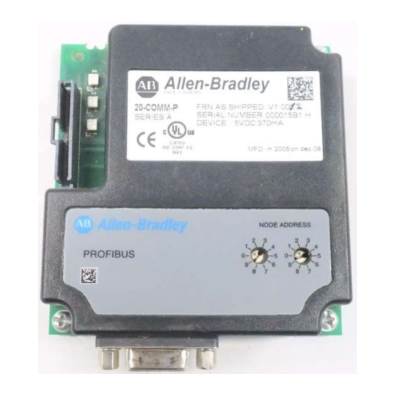
Chapter Getting Started The 20-COMM-P PROFIBUS adapter is an embedded communication option for any one drive in the PowerFlex family. It can also be used with other Allen-Bradley products implementing DPI™, a functional enhancement to SCANport™. Topic Page Topic Page... -
Page 10: Features
Compatible Products The PROFIBUS adapter is compatible with Allen-Bradley PowerFlex drives and other products that support DPI. DPI is a second generation peripheral communication interface and is a functional enhancement to SCANport. -
Page 11: Required Equipment
Getting Started Required Equipment Equipment Shipped with the Adapter When you unpack the adapter, verify that the package includes: ❑ One PROFIBUS adapter ❑ A 2.54 cm (1 in.) and a 15.24 cm (6 in.) Internal Interface cable (only one cable is needed to connect the adapter to the drive) ❑... -
Page 12: Safety Precautions
Getting Started Safety Precautions Please read the following safety precautions carefully ATTENTION: Risk of injury or equipment damage exists. Only personnel familiar with drive and power products and the associated machinery should plan or implement the installation, start-up, configuration, and subsequent maintenance of the product using a PROFIBUS adapter. -
Page 13: Quick Start
Getting Started Quick Start This section is designed to help experienced users start using the PROFIBUS adapter. If you are unsure about how to complete a step, refer to the referenced chapter. Step Refer to Review the safety precautions for the adapter. Throughout This Manual... -
Page 14: Modes Of Operation
Getting Started Modes of Operation The adapter uses three status indicators to report its operating status. They can be viewed on the adapter or through the drive cover. See Figure 1.2. Figure 1.2 Status Indicators – — ˜ – — ˜... -
Page 15: Installing The Adapter
Chapter Installing the Adapter Chapter 2 provides instructions for installing the adapter on a PowerFlex drive. Topic Page Preparing for an Installation Commissioning the Adapter Connecting the Adapter to the Network Connecting the Adapter to the Drive Applying Power Preparing for an Installation Before installing the PROFIBUS adapter: •... -
Page 16: Connecting The Adapter To The Network
Installing the Adapter 1. Set the node address switches. Figure 2.1 Setting the Node Address Tens Ones Digit Digit Setting Description 0-99 Node address used by the adapter if switches are enabled. The default switch setting is 05. Important: If the address switch is set to “00”, the adapter will use the setting of Parameter 03 - [P-DP Addr Cfg] for the node address. - Page 17 Installing the Adapter Figure 2.2 ERNI and Phoenix Subcon connectors Phoenix Subcon Plus 1M Connector ERNI Connector Figure 2.3 Network Wiring Diagram Only use cable that conforms to PROFIBUS cable standards. Belden #3079A PROFIBUS cable or equivalent is recommended.
- Page 18 Installing the Adapter Figure 2.4 20-COMM-P DB-9 pin layout Terminal Signal Function Housing Shield Not connected Not connected B-LINE Positive RxD/TxD, according to RS485 specification Request to send GND BUS Isolated GND from bus +5V BUS Isolated +5V from bus Not connected A-LINE Negative RxD/TxD...
-
Page 19: Connecting The Adapter To The Drive
Installing the Adapter Connecting the Adapter to the Drive 1. Remove power from the drive. 2. Use static control precautions. 3. Connect the Internal Interface cable to the DPI port on the drive and then to the DPI connector on the adapter. Figure 2.6 DPI Ports and Internal Interface Cables –... - Page 20 Installing the Adapter 4. Fold the Internal Interface cable behind the adapter and mount the adapter on the drive using the four captive screws to secure and ground it to the drive. Important: On a PowerFlex 70 drive, the screw in the lower right hole grounds the adapter.
-
Page 21: Applying Power
Installing the Adapter Applying Power ATTENTION: Risk of equipment damage, injury, or death exists. Unpredictable operation may occur if parameter settings and switch settings are not compatible with your application. Verify that settings are compatible with your application before applying power to the drive. - Page 22 Installing the Adapter...
-
Page 23: Configuring The Adapter
Chapter Configuring the Adapter Chapter 3 provides instructions and information for setting the parameters in the adapter. Topic Page Topic Page Configuration Tools Setting a Fault Action Using the PowerFlex HIM Resetting the Adapter Setting the Node Address Viewing the Adapter Configuration Setting the I/O Configuration For a complete list of parameters, refer to Appendix... -
Page 24: Using The Powerflex Him
Configuring the Adapter Using the PowerFlex HIM If your drive has either an LED or LCD HIM (Human Interface Module), access parameters in the adapter as follows: Using an LED HIM Step Key(s) Example Screens 1. Press the ALT and then Sel Device (Device) to display the Device Screen. -
Page 25: Setting The Node Address
Configuring the Adapter Setting the Node Address If the node address switches are set to “00”, the value of Parameter 03 - [P-DP Addr Cfg] determines the node address. 1. Set the value of Parameter 03 - [P-DP Addr Cfg] to a unique node address. -
Page 26: Setting A Fault Action
Configuring the Adapter 2. If Logic Command/Reference is enabled (default), configure the parameters in the drive to accept the Logic Command and Reference from the adapter. For example, set Parameter 90 - [Speed Ref A Sel] in a PowerFlex 70 or 700 drive to “DPI Port 5” so that the drive uses the Reference from the adapter. - Page 27 Configuring the Adapter To change the fault action • Set the values of Parameters 9 - [Comm Flt Action] and 10 - [Idle Flt Action] to the desired responses: Value Action Description Fault (default) The drive is faulted and stopped. (Default) Stop The drive is stopped, but not faulted.
-
Page 28: Resetting The Adapter
Configuring the Adapter Resetting the Adapter Changes to switch settings or some adapter parameters require that you reset the adapter before the new settings take effect. You can reset the adapter by cycling power to the drive or by using the following parameter: ATTENTION: Risk of injury or equipment damage exists. -
Page 29: Viewing The Adapter Configuration
Configuring the Adapter Viewing the Adapter Configuration The following parameters provide information about how the adapter is configured. You can view these parameters at any time. Number Name Description DPI Port The port on the drive to which the adapter is connected. Usually, it is port DPI Data Rate The data rate used by DPI in the drive. - Page 30 Configuring the Adapter...
-
Page 31: Configuring The Profibus Scanner
Chapter Configuring the Profibus Scanner Profibus scanners are available from several manufacturers, including SST. Chapter 4 provides instructions on how to utilize the SST Profibus configuration software tool to: • Install the 20-COMM-P GSD file in the software tool library •... - Page 32 Configuring the Profibus Scanner Figure 4.1 Example Profibus Network SYS LED COMM Config Port Front Label Profibus Port Station 0 PowerFlex 70 PowerFlex 70 Station 1 Station 2 SST Profibus Configuration Software Tool SST Profibus scanners come with a software tool for configuring the scanner (See Figure 4.2.)
-
Page 33: Installing The 20-Comm-P Gsd Files
Configuring the Profibus Scanner Installing the 20-COMM-P GSD file in the software tool library GSD files are used by software tools to configure the network, i.e. to map and define the I/O in a Profibus scanner. A GSD file is required for each type of adapter on the network. - Page 34 Configuring the Profibus Scanner Figure 4.4 Add Profibus devices Applet window. 4. Find the directory location of the data file(s) you wish to add (typically, the source location is a floppy disk in drive A:). “A_B_0572.gsd” is the GSD file for the 20-COMM-P as shown in Figure 4.5.
-
Page 35: Configuring The Sst-Pfb-Slc Profibus Scanner
4.6. Figure 4.6 Masters/Slaves Library window The software tool will automatically create an Allen-Bradley sub-folder (in the Slaves folder) if it does not already exist. The 20-COMM-P is now shown in the library and the software tool is now ready to configure a 20-COMM-P on a PROFIBUS network. - Page 36 SST sub-folder. Available DP masters are displayed in this sub-folder. 2. Click on the (+) sign of the Slaves folder in the Library window and the Allen-Bradley sub-folder to display the available DP slaves or the 20-COMM-P slave. Refer to Figure 4.6.
- Page 37 Figure 4.10. Double-click on the scanner in the network window. Figure 4.10 Scanner Network window 9. Double-click on the 20_COMM_P listed in the Allen-Bradley library folder. A user-defined Name and Description can be given to this 20-COMM-P. In our example, this device will be Station 1 on the network. Other stations may be chosen by using the arrow to display a drop-down list in the Station window.
- Page 38 Configuring the Profibus Scanner Logic Command/ Status, Reference / Feedback, Datalinks and Parameter Access (explicit messaging) modules are added using the Modules tab. 10. Click on the Modules tab. Click Add to view the choice of modules. Figure 4.12 20-COMM-P Modules Tab In our example, Station 1 will be controlled using Logic Command / Status and Reference / Feedback.
- Page 39 Configuring the Profibus Scanner Figure 4.14 Modules: Ctrl/Stat & Ref/Fdbk Viewing Window Station 1 will be configured to use Datalinks A1 and A2. The PowerFlex 70 utilizes 16-bit Datalinks. 13. Click Add to continue adding modules. Select “Datalink A (2x2bytes)” and click OK. Figure 4.15 Add Modules: Datalink A Selection Window 14.
- Page 40 4-10 Configuring the Profibus Scanner Figure 4.16 Modules: Datalink A Viewing Window Station 1 will also be configured to use Datalinks B1 and B2. The PowerFlex 70 utilizes 16-bit Datalinks. 15. Click Add to continue adding modules. Select “Datalink B (2x2 bytes)”...
- Page 41 Configuring the Profibus Scanner 4-11 Figure 4.18 Modules: Datalink B Viewing Window Station 1 will also be configured to use Datalinks C1 and C2. The PowerFlex 70 utilizes 16-bit Datalinks. 17. Click Add to continue adding modules. Select “Datalink C (2x2 bytes)”...
- Page 42 4-12 Configuring the Profibus Scanner Figure 4.20 Modules: Datalink C Viewing Window Station 1 will also be configured to use Datalinks D1 and D2. The PowerFlex 70 utilizes 16-bit Datalinks. 19. Click Add to continue adding modules. Select “Datalink D (2x2 bytes)”...
- Page 43 Configuring the Profibus Scanner 4-13 21. Click Add to continue adding modules. Select “Parameter Access” and click OK. Figure 4.22 Add Modules: Parameter Access Selection Window 22. The “Parameter Access” module has now been added as shown in Figure 4.23. Figure 4.23 Modules: Parameter Access Viewing Window Settings can be chosen to map Station modules to SLC addresses.
- Page 44 4-14 Configuring the Profibus Scanner 23. Click on the SLC Address tab as shown in Figure 4.24. Figure 4.24 SLC Address: M1/M0 (Ctrl/Stat & Ref/Fdbk) 24. Datalink A is at word 2 in the M1/M0 files as shown in Figure 4.25.
- Page 45 Configuring the Profibus Scanner 4-15 25. Datalink B is at word 4 in the M1/M0 files as shown in Figure 4.26. Figure 4.26 SLC Address: M1/M0 (Datalink B) 26. Datalink C is at word 6 in the M1/M0 files as shown in Figure 4.27.
- Page 46 4-16 Configuring the Profibus Scanner 27. Datalink D is at word 8 in the M1/M0 files as shown in Figure 4.28. Figure 4.28 SLC Address: M1/M0 (Datalink D) 28. Parameter Access starts at word 10 in the M1/M0 files. Note that Parameter Access utilizes 4 words (10-13). Click OK when finished.
- Page 47 Configuring the Profibus Scanner 4-17 Station 1 is configured as follows: Module M1/M0 Word Ctrl/Stat & Ref Fdbk Datalink A Datalink B Datalink C Datalink D Parameter Access Note that Station 1 occupies 14 words (0-13). 30. The same steps for configuring Station 1 will be used for configuring Station 2.
- Page 48 4-18 Configuring the Profibus Scanner Figure 4.32 Network window scanner selection 33. Click File and Save As from the tool bar, as a unique File Name. The configuration of the scanner is now complete. Note that cycling power to the scanner is recommended. (See Figure 4.33.) Figure 4.33 Save As Dialogue window...
-
Page 49: Gsd Diagnostic Messages
Configuring the Profibus Scanner 4-19 GSD Diagnostic Messages In the case of invalid GSD module configuration, the peripheral will send one of the following messages: Fault Description No Ctrl/Stat & Ref/Fdbk The Ctrl/Stat & Ref/Fdbk module must always be used and placed first in the configuration. - Page 50 4-20 Configuring the Profibus Scanner...
-
Page 51: About I/O Messaging
Chapter Using I/O Messaging Chapter 5 provides information and examples that explain how to use I/O Messaging to control a PowerFlex drive. Topic Page Topic Page About I/O Messaging SLC Example Ladder Logic Program 5-6 Understanding the I/O Image SLC Ladder Logic Example - Main Program Using Logic Command/Status SLC Ladder Logic Example - Station... -
Page 52: Understanding The I/O Image
Using I/O Messaging Understanding the I/O Image The terms input and output are defined from scanner’s point of view. Therefore, Outputs are data that is output from the scanner and consumed by the PROFIBUS adapter. Inputs are status data that is produced by the adapter and consumed as input by the scanner. - Page 53 Using I/O Messaging An image that uses 32-bit words for Reference and Datalinks would change the I/O image in Figure 5.1 as follows: Word Word Logic Command/Status 7 - 10 Datalink B 1 - 2 Reference/Feedback 11 - 14 Datalink C 3 - 6 Datalink A 15 - 18...
-
Page 54: Using Logic Command/Status
Using I/O Messaging Using Logic Command/Status When enabled, the Logic Command/Status word is always word 0 in the I/O image. The Logic Command is a 16-bit word of control produced by the scanner and consumed by the adapter. The Logic Status is a 16-bit word of status produced by the adapter and consumed by the scanner. - Page 55 Using I/O Messaging 32-Bit Parameters using 16-Bit Datalinks To read (and/or write) a 32-bit parameter using 16-bit Datalinks, typically both Datalinks (A,B,C,D) are set to the 32-bit parameter. For example, to read Parameter 09 - [Elapsed MWh], both Datalink A1 and A2 are set to “9.”...
-
Page 56: Slc Example Ladder Logic Program
Using I/O Messaging SLC Example Ladder Logic Program The Profibus example program uses a SLC processor with an SST Profibus scanner (SST-PFB-SLC) in the first slot of the rack and will work with PowerFlex 70 or PowerFlex 700 drives. Function of the Example Program The program is written for (2) drives on the network and demonstrates using: •... - Page 57 Using I/O Messaging Parameter Settings Device Parameter Name Value Description Speed Ref A Sel ‘DPI Port 5’ (20-COMM-P) Data In A1 Points to Pr. 140 [Accel Time 1] Data In A2 Points to Pr. 142 [Decel Time 1] Data In B1 Points to Pr.
- Page 58 Using I/O Messaging The two PROFIBUS adapters are setup as Station 1 and Station 2, and are configured as 14 words input & output each (See Chapter SLC Data Table Read Data File N10: contains the actual read data that can be used elsewhere in the ladder program.
-
Page 59: Slc Ladder Logic Example - Main Program
Using I/O Messaging Logic Command/Status Words These examples use the Logic Command word and Logic Status word for PowerFlex 70 and PowerFlex 700 drives. Refer to Appendix Logic Command/Status Words for more information. The definition of the bits in these words may vary if you are using a different DPI Host product. - Page 60 5-10 Using I/O Messaging Figure 5.4 Example SLC Ladder Logic - Main Program (Continued) Profibus scanners vary from manufacturer to manufacturer in how the bytes are ordered in a word. For example, some Profibus scanners operate with high & low bytes swapped (the value "1234" is represented as "3412"). The READ data is copied into N10: and the bytes are reversed in the SWP instruction below so a value such as "3412"...
- Page 61 Using I/O Messaging 5-11 Figure 5.4 Example SLC Ladder Logic - Main Program (Continued) Execute LAD 4 - Station 2 Drive Logic Jump To Subroutine 0006 SBR File Number The Profibus scanner is configured for 28 bytes (14 words) of outputs for each drive. Two drives require 48 bytes (28 words). Station 1 Station 2 Description...
- Page 62 5-12 Using I/O Messaging Figure 5.5 SLC Ladder Logic Example - Main Program Write the drives data to the Profibus scanner. SST Scanner Write Data Word 0 0009 Copy File Source #N21:0 Dest #M0:1.0 Length 0010...
-
Page 63: Slc Ladder Logic Example - Station 1 Program
Using I/O Messaging 5-13 SLC Ladder Logic Example - Station 1 Program Figure 5.6 Example SLC Ladder Logic - Station 1 Program Controlling the Logic Command word in the drive. B3:20 /* bits are controlled elsewhere in the user program. Station 1 Station 1 Start... - Page 64 5-14 Using I/O Messaging Figure 5.6 Example SLC Ladder Logic - Station 1 Program (Continued) Station 1 Datalink A1 Datalink A1 (Pr. 300) set to Acceleration Time 1 (Pr. 140). N19:2 is controlled elsewhere in the user program. Station 1 Datalink A1 Write Move...
- Page 65 Using I/O Messaging 5-15 Figure 5.6 Example SLC Ladder Logic - Station 1 Program (Continued) Station 1 Datalink B2 Datalink B2 (Pr. 303) set to Stop Mode A (Pr. 155). N19:5 is controlled elsewhere in the user program. Station 1 Datalink B2 Write 0010...
- Page 66 5-16 Using I/O Messaging Figure 5.6 Example SLC Ladder Logic - Station 1 Program (Continued) Station 1 Datalink D1 Datalink D1 (Pr. 306) set to Preset Speed 3 (Pr. 103). N19:8 is controlled elsewhere in the user program. Station 1 Datalink D1 Write 0013...
-
Page 67: Slc Ladder Logic Example - Station 2 Program
Using I/O Messaging 5-17 SLC Ladder Logic Example - Station 2 Program Figure 5.7 Example SLC Ladder Logic - Station 2 Program Controlling the Logic Command word in the drive. B3:21 /* bits are controlled elsewhere in the user program. Station 2 Station 2 Start... - Page 68 5-18 Using I/O Messaging Figure 5.7 Example SLC Ladder Logic - Station 2 Program (Continued) Station 2 Speed Reference PowerFlex 70 Speed Ref A Sel (Pr.90) needs to be set to 'DPI Port 5'. N19:15 is controlled elsewhere in the user program. Station 2 Speed Reference Write...
- Page 69 Using I/O Messaging 5-19 Figure 5.7 Example SLC Ladder Logic - Station 2 Program (Continued) Station 2 Datalink B1 Datalink B1 (Pr. 302) set to Jog Speed (Pr. 100). N19:18 is controlled elsewhere in the user program. Station 2 Datalink B1 Write Move 0009...
- Page 70 5-20 Using I/O Messaging Figure 5.7 Example SLC Ladder Logic - Station 2 Program (Continued) Station 2 Datalink C2 Datalink C2 (Pr. 305) set to Preset Speed 2 (Pr. 102). N19:21 is controlled elsewhere in the user program. Station 2 Datalink C2 Write 0012...
-
Page 71: Using Explicit Messaging
Chapter Using Explicit Messaging (Parameter Protocol) Chapter 6 provides information and examples that explain how to use Explicit Messaging to monitor and configure the adapter and connected PowerFlex drive, as well as other peripherals. Topic Page Topic Page About Explicit Messaging SLC Ladder Example - Station 1 6-11 Parameter Protocol... -
Page 72: Running Explicit Messages
Using Explicit Messaging (Parameter Protocol) To be able to use the parameter protocols in the 20-COMM-P, the Parameter Access module in the GSD file must be added to the master configuration when configuring the network. Refer to step #21, Page 4-13 to view the procedure for adding the “Parameter Access”... -
Page 73: Parameter Protocol
Using Explicit Messaging (Parameter Protocol) Event 1. You format the required data and set up the ladder logic program to send an Explicit Message request to the scanner module (download). 2. The scanner module transmits the Explicit Message Request to the slave device over the PROFIBUS network. - Page 74 Using Explicit Messaging (Parameter Protocol) efer to Page 6-4 Page 6-5 for a description of the data that is required in each word. Parameter Message Request Word Description PNU - Parameter Number (Bit 0-10) The parameter number determines which parameter to access, in the selected peripheral.
- Page 75 Using Explicit Messaging (Parameter Protocol) Parameter Message Response Word Description PNU - Parameter Number (Bit 0-10) Requested parameter number. SPM (Bit 11) Reserved - is always set to 0. RC - Response Code (Bit 12-15) One of the following codes will be sent: 0 = No request 1 = Transfer parameter value (8-bit &...
- Page 76 Using Explicit Messaging (Parameter Protocol) Parameter Protocol Examples Read Examples Figure 6.3 Overview Parameter Message Format (Read Request) Request Response Bit 15-12 10-0 15-12 10-0 Parameter Access Word 1 (PCA) Parameter Access Subindex Subindex Word 2 (IND) Parameter Access Not Used Parameter value high Word 3 (PVA) (32 bit high word)
- Page 77 Using Explicit Messaging (Parameter Protocol) Reading Parameter 140 [Accel Time 1] from the PowerFlex 70 (DPI Port 0) 1000 hex = Read Command 108C 8C hex = 140 dec (Pr. 140) DPI Port 0 (DPI Host) Not Used Not Used Transferring 16-bit parameter value ("1") 108C Reply...
- Page 78 Using Explicit Messaging (Parameter Protocol) Reading Par. 244 [Fault 1 Time] from the PowerFlex 70 (DPI Port 0) 1000 hex = Read Command 10F4 F4 hex = 244 dec (Pr. 244) DPI Port 0 (DPI Host) Not Used Not Used Transferring 16-bit parameter value ("1") 10F4 Reply...
- Page 79 Using Explicit Messaging (Parameter Protocol) Request Response “2” (‘0010’ binary) to write a 8-bit or 16-bit “1” (0001’) Transferring a 8-bit or 16-bit parameter parameter value “3” (‘0011 binary) to write a 32-bit “2” (‘0010’) Transferring a 32-bit parameter parameter value “7”...
- Page 80 6-10 Using Explicit Messaging (Parameter Protocol) Writing Parameter 9 [Comm Fault Action] to the 20-COMM-P on a PowerFlex 70 (DPI Port 5) 2000 hex = Change parameter value 8-bit/16-bit Command 2009 9 hex = 9 dec (Pr. 9) DPI Port 5 (20-COMM-P) Not Used 2 hex = 2 dec = Zero Data 1009...
-
Page 81: Slc Ladder Example - Station 1 Parameter Protocol
Using Explicit Messaging (Parameter Protocol) 6-11 SLC Ladder Example - Station 1 Parameter Protocol Figure 6.5 Example SLC Ladder Logic - Station 1 Parameter Protocol This section of the routine is only needed if the application needs to perform Parameter Protocol Reads or Writes to Station 1. On power-up, initialize the Parameter Protocol routine. - Page 82 6-12 Using Explicit Messaging (Parameter Protocol) Figure 6.5 Example SLC Ladder Logic - Station 1 Parameter Protocol (Continued) N10:10 is the Station 1 Response Parameter Access Word 1. It is < > 0 when a message has been received in response to a message request.
-
Page 83: Slc Ladder Example - Station 2 Parameter Protocol
Using Explicit Messaging (Parameter Protocol) 6-13 SLC Ladder Example - Station 2 Parameter Protocol Figure 6.6 Example SLC Ladder Logic - Station 2 Parameter Protocol This section of the routine is only needed if the application needs to perform Parameter Protocol Reads or Writes to Station 2. Station 2 On power-up, initialize the Parameter Protocol routine. - Page 84 6-14 Using Explicit Messaging (Parameter Protocol) Figure 6.6 Example SLC Ladder Logic - Station 2 Parameter Protocol (Continued) N10:24 is the Station 2 Response Parameter Access Word 1. It is < > 0 when a message has been received in response to a message request.
- Page 85 Using Explicit Messaging (Parameter Protocol) 6-15 Notes:...
- Page 86 6-16 Using Explicit Messaging (Parameter Protocol)
-
Page 87: Troubleshooting
Chapter Troubleshooting Chapter 7 contains troubleshooting information. Topic Page Topic Page Locating the Status Indicators NET A Status Indicator PORT Status Indicator Adapter Diagnostic Items MOD Status Indicator Viewing and Clearing Events Locating the Status Indicators The PROFIBUS adapter has three status indicators. They can be viewed on the adapter or through the drive cover. -
Page 88: Port Status Indicator
• Orange The adapter is connected Connect the adapter to a product that to a product that does not supports Allen-Bradley DPI communications support Allen-Bradley DPI (for example, PowerFlex drives). communications. • Flashing Green The adapter is establishing No Action. -
Page 89: Mod Status Indicator
Troubleshooting MOD Status Indicator Status Cause Corrective Action • The adapter is not Securely connect the adapter to the powered. PowerFlex drive using the ribbon cable. • Apply power to the drive and network. • Flashing Red The adapter has failed the Cycle power to the drive. -
Page 90: Adapter Diagnostic Items
Troubleshooting Adapter Diagnostic Items Adapter Diagnostic Items are viewable with DriveExplorer (version 2.01 or higher), DriveExecutive (version 1.01 or higher) or HIM (2.001) software. Event Description Common Logic The current value of the Common Logic Command being transmitted to the host. Prod Logic Cmd The current value of the Product-specific Logic Command being transmitted to the host. -
Page 91: Viewing And Clearing Events
Troubleshooting Viewing and Clearing Events The adapter maintains an event queue that reports the history of its actions. You can view the event queue using an LCD PowerFlex HIM, DriveExplorer (2.01 or higher) software, or DriveExecutive (1.01 or higher). Step Keys Example Screen Viewing Events... - Page 92 Troubleshooting Events Many events in the Event queue occur under normal operation. If you encounter unexpected communications problems, the events may help you or Allen-Bradley personnel troubleshoot the problem. The following events may appear in the event queue: Code Event...
- Page 93 Troubleshooting Code Event Description P-DP Offline The PROFIBUS adapter has gone off-line the PROFIBUS network. P-DP Idle The PROFIBUS adapter received a network clear from the PROFIBUS master. Language The language flash segment is corrupt - flash the adapter. CRC Bad...
- Page 94 Troubleshooting...
-
Page 95: Appendix A Specifications
Appendix Specifications This chapter presents the specifications for the adapter. Topic Page Topic Page Communications Environmental Electrical Regulatory Compliance A-2 Mechanical Communications Network Protocol PROFIBUS Data Rates 9.6K, 19.2K, 45.45K, 93.75K, 187.5K, 500K, 1.5M, 3M, 6M, 12M. The adapter has auto baud rate detection. Drive Protocol Data Rates... -
Page 96: Environmental
Specifications Environmental Temperature Operating -10 to 50°C (14 to 149°F) Storage -40 to +85°C (-40 to 185°F) Relative Humidity 5 to 95% non-condensing Regulatory Compliance 508C and CUL EN50081-2 (1993) and EN61000-6-2 (1999) -
Page 97: About Parameter Numbers
Appendix Adapter Parameters Appendix B provides information about the PROFIBUS adapter parameters. Topic Page About Parameter Numbers B-1 Parameter List About Parameter Numbers The parameters in the adapter are numbered consecutively. However, depending on which configuration tool you use, they may have different numbers. - Page 98 Adapter Parameters Parameter No. Name and Description Details [P-DP Rate Actual] Default: PROFIBUS data rate. Values: 0 = 9.6 K 1 = 19.2 K 2 = 45.45 K 3 = 93.75 K 4 = 187.5 K 5 = 500 K 6 = 1.5 M 7 = 3 M 8 = 6 M...
- Page 99 Adapter Parameters Parameter No. Name and Description Details [DPI I/O Config] Default: xxx0 0001 I/O that is transferred through the adapter. Bit Values: 0 = I/O disabled 1 = I/O enabled Type: Read/Write Reset Required: Bit Definitions 0 = Cmd/Ref Default 1 = Datalink A 2 = Datalink B...
- Page 100 Adapter Parameters Parameter No. Name and Description Details [Flt Cfg A1] Default: [Flt Cfg A2] Default: [Flt Cfg B1] Default: [Flt Cfg B2] Default: [Flt Cfg C1] Default: [Flt Cfg C2] Default: [Flt Cfg D1] Default: [Flt Cfg D2] Default: Sets the data that is sent to the Datalink in the Minimum: drive if any of the following is true:...
- Page 101 Adapter Parameters Notes:...
- Page 102 Adapter Parameters...
-
Page 103: Appendix C Logic Command/Status Words
Appendix Logic Command/Status Words Appendix C provides the definitions of the Logic Command/Logic Status words that are used for some products that can be connected to the Profibus adapter. If you do not see the Logic Command/Logic Status for the product that you are using, refer to your product’s documentation. PowerFlex 70 and PowerFlex 700 Drives Logic Command Word Logic Bits... - Page 104 Logic Command/Status Words PowerFlex 70 and PowerFlex 700 Drives Logic Status Word Logic Bits 15 14 13 12 11 10 9 8 7 6 5 4 3 2 1 0 Status Description x Ready 0 = Not Ready 1 = Ready Active 0 = Not Active 1 = Active...
-
Page 105: Glossary
“cards,” “embedded communication options,” “gateways,” “modules,” and “peripherals.” ControlFLASH ControlFLASH is an Allen-Bradley software tool that lets users electronically update firmware on printed circuit boards. The tool takes advantage of the growing use of flash memory (electronic erasable chips) across industrial control products. - Page 106 The drive determines the size of Datalinks. DPI is a second generation peripheral communication interface used by various Allen-Bradley drives and power products. It is a functional enhancement to SCANport. DriveExplorer Software DriveExplorer software is a tool for monitoring and configuring Allen-Bradley products and adapters.
- Page 107 Glossary-3 Fault Configuration When communications are disrupted (for example, a cable is disconnected), the adapter and PowerFlex drive can respond with a user-defined fault configuration. The user sets the data that is sent to the drive in the fault configuration parameters (Parameters 13 - [Flt Cfg Logic] through 22 - [Flt Cfg D2]).
- Page 108 Glossary-4 I/O Data I/O transmit time-critical data such as a Logic Command and Reference. The terms “input” and “output” are defined from the scanner’s point of view. Output is transmitted by the scanner and consumed by the adapter. Input is transmitted by the adapter and consumed by the scanner. Logic Command/Logic Status The Logic Command is used to control the PowerFlex drive (e.g., start, stop, direction).
- Page 109 Glossary-5 PowerFlex Drives The Allen-Bradley PowerFlex family of drives includes PowerFlex 70, PowerFlex 700, and PowerFlex 7000 drives. These drives can be used for applications ranging from 0.37 kW (0.5 HP) to 3,000 kW (4,000 HP). All PowerFlex drives implement DPI, allowing them to use the 20-COMM-P PROFIBUS adapter.
- Page 110 Glossary-6 Zero Data When communications are disrupted (for example, a cable is disconnected), the adapter and drive can respond with zero data. Zero data results in the drive receiving zero as values for command data. If the drive was running and using the Reference from the adapter, it will stay running but at zero Reference.
- Page 111 Allen-Bradley, ControlFLASH, DPI, DriveExplorer, DriveTools32, DriveTools 2000, DriveExecutive, PLC-5, PowerFlex, SCANport, and SLC are trademarks of Rockwell Automation. PROFIBUS is a trademark of the PROFIBUS Trade Organization. RSLogix is a trademark of Rockwell Software. Windows, Windows CE, Windows NT, and Microsoft are either...
-
Page 113: Index
Index catalog number, 1-1 Comm Flt Action parameter, B-2 adapter commissioning the adapter, 2-1 adding to the scan list, 4-3 applying power, 2-7 communications module, refer to commissioning, 2-1 adapter compatible products, 1-2 compatible products, 1-2 components, 1-1 components, 1-1 definition, G-1 configuration tools, 3-1 features, 1-2... - Page 114 Index-2 DPI Port parameter, B-1 firmware release, P-2 DriveExplorer flash update, G-3 accessing parameters with, 3-1 Flt Cfg A1 - D2 parameters, B-4 definition, G-2 Flt Cfg Logic parameter, B-3 supported features, 1-2 Flt Cfg Ref parameter, B-3 Drives, see PowerFlex drives formatting Explicit Messages, 6-4 DriveTools 2000 accessing parameters with, 3-1...
- Page 115 Index-3 installation applying power to the adapter, NET A status indicator locating, 7-1 commissioning the adapter, troubleshooting with, 7-3 node address connecting to the drive, 2-5 definition, G-4 connecting to the network, 2-2 setting with a parameter, 3-3 preparing for, 2-1 setting with switches, 2-2 Internal Interface cable, 2-5 Non-Volatile Storage (NVS)
- Page 116 Index-4 quick start, 1-5 technical support, P-2 tools required, 1-3 troubleshooting, 7-1 to 7-7 Ref/Fdbk Size parameter, B-2 Reference/Feedback definition, G-5 update, see flash update in I/O image, 5-2 using, 5-5 regulatory compliance, A-2 web site related documentation, P-1 for GSD files, G-3 Reset Module parameter, B-2 for manuals, P-1 resetting an adapter, 3-6...
- Page 117 Publication 20COMM-UM006A-EN-P - November, 2001 P/N 196064-P01 Copyright (C) 2001 Rockwell Automation. All rights reserved. Printed in USA.
Need help?
Do you have a question about the PowerFlex 20-COMM-P FRN 1 Series and is the answer not in the manual?
Questions and answers