Table of Contents
Advertisement
Quick Links
Advertisement
Table of Contents

Related Manuals for Allen-Bradley PowerFlex 22-COMM-B


Summary of Contents for Allen-Bradley PowerFlex 22-COMM-B
- Page 1 PowerFlex® 22-COMM-B BACnet MS/TP Adapter Firmware Version 1.xxx User Manual...
- Page 2 Burn Hazard labels may be located on or inside the equipment (e.g., drive or motor) to alert people that surfaces may be at dangerous temperatures. Allen-Bradley, PowerFlex, DriveExplorer, DriveExecutive, DriveTools SP, and ControlFLASH are trademarks of Rockwell Automation, Inc. Trademarks not belonging to Rockwell Automation are property of their respective companies.
- Page 3 Summary of Changes The information below summarizes the changes made to this manual since its last release (October 2006): Description of Changes Page(s) Updated information in the “Related Documentation” section. In the “Compatible Products” section, added the PowerFlex 4M drive. NOTE: The 22-COMM-B adapter must have firmware version 1.003 (or later) to be compatible with the PowerFlex 4M drive.
- Page 4 soc-ii Summary of Changes...
-
Page 5: Table Of Contents
Table of Contents Preface About This Manual Related Documentation ......P-1 Rockwell Automation Support......P-2 Conventions Used in this Manual . - Page 6 Table of Contents Chapter 5 Troubleshooting Understanding the Status Indicators ....5-1 PORT Status Indicator ......5-2 MOD Status Indicator .
-
Page 7: Preface
Preface About This Manual Topic Page Related Documentation Rockwell Automation Support Conventions Used in this Manual P-2 Related Documentation For: Refer to: Publication DriveExplorer™ http://www.ab.com/drives/driveexplorer, and — DriveExplorer online Help (installed with the software) DriveTools™ SP (includes http://www.ab.com/drives/drivetools, and — DriveExecutive™) DriveExecutive online Help (installed with the software) PowerFlex 4-Class HIM... -
Page 8: Rockwell Automation Support
Technical Product Assistance For technical assistance, please review the information in Chapter Troubleshooting first. If you still have problems, then access the Allen-Bradley Technical Support web site at www.ab.com/support/ abdrives or contact Rockwell Automation, Inc. Conventions Used in this Manual This manual provides information about the adapter and using it with PowerFlex 4-Class drives. -
Page 9: Getting Started
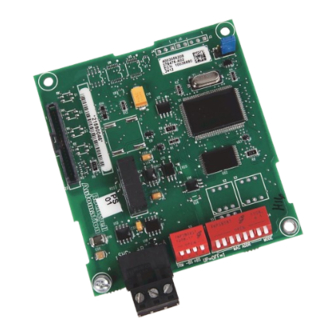
Chapter Getting Started The adapter is intended for installation into a PowerFlex 40 or PowerFlex 400 drive and is used for network communication. The adapter can also be installed in a DSI External Comms Kit (22-XCOMM-DC-BASE). This kit enables PowerFlex 4 and PowerFlex 4M drives, which cannot accommodate an internally-mounted adapter, to connect to a BACnet MS/TP network. -
Page 10: Features
Getting Started Features The adapter features include: • Typical mounting in a PowerFlex 40 or PowerFlex 400 drive. The adapter can also be installed in a DSI External Comms Kit (22-XCOMM-DC-BASE). • Switches that enable you to: – Set a MAC address before applying power to the drive. –... -
Page 11: Compatible Products
Getting Started Compatible Products The adapter is compatible with Allen-Bradley PowerFlex 4-Class (Component-Class) drives and other products that support an internal DSI adapter. At the time of publication, compatible products include: • PowerFlex 4 drives (when used with DSI External Comms Kit) •... -
Page 12: Safety Precautions
Getting Started Safety Precautions Please read the following safety precautions carefully. ATTENTION: Risk of injury or death exists. The PowerFlex drive may contain high voltages that can cause injury or death. Remove power from the PowerFlex drive, and then verify power has been discharged before installing or removing an adapter. - Page 13 Getting Started ATTENTION: Risk of injury or equipment damage exists. When a system is configured for the first time, there may be unintended or incorrect machine motion. Disconnect the motor from the machine or process during initial system testing. ATTENTION: Risk of injury or equipment damage exists. The examples in this publication are intended solely for purposes of example.
-
Page 14: Quick Start
Getting Started Quick Start This section is provided to help experienced users quickly start using the adapter. If you are unsure how to complete a step, refer to the referenced chapter. Step Action Refer to … Review the safety precautions for the adapter. Throughout this manual Verify that the PowerFlex drive is properly installed. -
Page 15: Status Indicators
Getting Started Status Indicators The adapter uses four status indicators to report its operating status. They can be viewed on the adapter or through the drive cover (Figure 1.2). Figure 1.2 Status Indicators (location on drive may vary) Bottom side of adapter board Item Name PORT... - Page 16 Getting Started Notes:...
-
Page 17: Installing The Adapter
Chapter Installing the Adapter This chapter provides instructions for installing the adapter in a PowerFlex 40 or PowerFlex 400 drive. This adapter can also be installed in a DSI External Comms Kit. In this case, refer to the 22-XCOMM-DC-BASE Installation Instructions (publication 22COMM-IN001) supplied with the kit. - Page 18 Installing the Adapter Setting the MAC Address Set the MAC address using the MAC Address switches (Figure 2.1). Refer to Table 2.A for specific MAC address switch settings. Important: Each node on the network must have a unique MAC address. Set the MAC address before power is applied because the adapter uses the MAC address it detects when it first receives power.
- Page 19 Installing the Adapter Table 2.A MAC Address Switch Settings (UP = 1 = OPEN) (Continued) Switch Setting Switch Setting Address Address SW1 SW2 SW3 SW4 SW5 SW6 SW7 SW1 SW2 SW3 SW4 SW5 SW6 SW7...
- Page 20 — Since nodes on a BACnet MS/TP network are typically a mix of Allen-Bradley PowerFlex drives and other brands of building automation products, the network node locations for the PowerFlex drives will determine how their adapter’s TERM, -BIAS, and +BIAS switches...
-
Page 21: Bias Switches
Installing the Adapter Network with PowerFlex Drives at Starting and/or Ending Nodes For a network with PowerFlex drives at the starting and/or ending nodes (Figure 2.3), set their 22-COMM-B adapter’s TERM, -BIAS, and +BIAS switches to the “Down” (On) position. All other PowerFlex drive network nodes must have these switches set to the “Up”... -
Page 22: Connecting The Adapter To The Drive
Installing the Adapter Connecting the Adapter to the Drive PowerFlex 40 Frames B and C, and PowerFlex 400 Frame C 1. Remove power from the drive, and remove the drive cover. 2. Use static control precautions. 3. Mount the adapter on the required special drive cover (ordered separately;... - Page 23 Installing the Adapter 4. Connect the Internal Interface cable to the DSI port on the drive and then to the mating DSI connector on the adapter. Figure 2.6 Connecting DSI Ports with Internal Interface Cable 22-COMM-B Adapter Back of Required Special Drive Cover PowerFlex 40 Drive (Frame C shown with cover removed)
- Page 24 Installing the Adapter PowerFlex 400 Frames D, E, and F 1. Remove power from the drive, and open the drive cover. 2. Use static control precautions. 3. With the adapter board right side up, remove its mounting screw from the lower left hole. Save the screw for mounting in Step 6. 4.
-
Page 25: Applying Power
Installing the Adapter Applying Power ATTENTION: Risk of equipment damage, injury, or death exists. Unpredictable operation may occur if you fail to verify that parameter settings and switch settings are compatible with your application. Verify that settings are compatible with your application before applying power to the drive. - Page 26 2-10 Installing the Adapter Table 2.B Drive and Adapter Start-Up Status Indications Item Name Color State Description Drive FAULT Status Indicator FAULT Drive ready but not running, and no faults are present. Flashing A fault has occurred. Adapter Status Indicators PORT Green Flashing...
-
Page 27: Connecting The Drive/Adapter To The Network
Installing the Adapter 2-11 The following steps in this section assume that the drive will receive the Logic Command and Reference from the BACnet MS/TP network. 1. Using drive Parameter P038 - [Speed Reference], set the drive speed Reference to “5” (Comm Port). 2. - Page 28 2-12 Installing the Adapter 5. Insert the 3-pin linear plug into the mating adapter socket. 6. Close or install the drive cover. 7. Apply power to the drive. 8. Verify that adapter Parameter 07 - [Baud Rate Act] is reporting the actual network baud rate.
-
Page 29: Configuring The Adapter
Chapter Configuring the Adapter This chapter provides information and instructions for setting the parameters in the adapter. Topic Page Configuration Tools Using the Optional, External PowerFlex 4-Class HIM Setting the Device Instance Number Setting a Comm Loss Action Setting the Comm Loss Time Setting the Baud Rate Resetting the Adapter Viewing the Adapter Status Using Parameters... -
Page 30: Using The Optional, External Powerflex 4-Class Him
Configuring the Adapter Using the Optional, External PowerFlex 4-Class HIM Adapter parameters cannot be accessed using the integral keypad on a PowerFlex 4-Class drive. You must use DriveExplorer or DriveExecutive software, or an optional, external PowerFlex 4-Class HIM (22-HIM-A3 or 22-HIM-C2S). See Figure 3.1 for styles. - Page 31 Configuring the Adapter NOTE: All configuration procedures throughout this chapter use the optional, external PowerFlex 4-Class HIM to access parameters in the adapter and show example HIM screens. Figure 3.1 Optional, External PowerFlex 4-Class HIMs Stopped Auto Stopped Auto DISP LANG DISP LANG...
-
Page 32: Setting The Device Instance Number
Configuring the Adapter Setting the Device Instance Number While there are many ways to implement Device Instance and network strategies, the example shown in Figure 3.2 illustrates one logical approach. In this example, two individual Floor Level Networks are connected to the Building Level Network through a router which allows devices on each network to share the same MAC address. - Page 33 Configuring the Adapter high portion (most significant digits) of the number and Parameter 12 - [Device Inst Lo] to enter the low portion (always the three least significant digits) of the number. Figure 3.3 illustrates how to apportion the Device Instance Number for entry into the adapter. Figure 3.3 Apportioning the Device Instance Number for Entry Device Instance Number Most Significant Digits...
-
Page 34: Setting A Comm Loss Action
Configuring the Adapter Setting a Comm Loss Action By default, when communications are disrupted (for example, a cable is disconnected), the drive responds by faulting if it is using I/O from the network. You can configure a different response to communication disruptions using Parameter 02 - [Comm Loss Action]. -
Page 35: Setting The Comm Loss Time
Configuring the Adapter Setting the Fault Configuration Parameters If you set Parameter 02 - [Comm Loss Action] to “Send Flt Cfg,” the values in the following parameters are sent to the drive after a communications fault occurs. You must set these parameters to values required by your application. -
Page 36: Setting The Baud Rate
Configuring the Adapter Setting the Baud Rate The value of Parameter 06 - [Baud Rate Cfg] determines the baud rate used by the adapter. The Autobaud setting will detect the baud rate used on the network if another device is setting the baud rate. Your application may require a different setting. -
Page 37: Resetting The Adapter
Configuring the Adapter Resetting the Adapter Changes to switch settings and some adapter parameters require that you reset the adapter before the new settings take effect. You can reset the adapter by cycling power to the drive or by using Parameter 01 - [Reset Module]. -
Page 38: Viewing The Adapter Status Using Parameters
22-SCM-232 serial converter module (firmware version 2.005 or later). When flashing over the network, you can use the Allen-Bradley software tool ControlFLASH, the built-in flash capability of DriveExplorer Lite or Full, or the built-in flash capability of DriveExecutive. -
Page 39: Using Bacnet Objects
Chapter Using BACnet Objects This chapter provides information about controlling a PowerFlex 4-Class drive using BACnet objects. Topic Page Understanding BACnet Objects Basic Drive Operation on the Network Supported BACnet Objects Understanding BACnet Objects BACnet nodes are controlled and monitored by the use of several types of objects. -
Page 40: Basic Drive Operation On The Network
Using BACnet Objects Basic Drive Operation on the Network This section describes how to operate a drive on the network using a combination of BACnet object types for basic control. ATTENTION: Control information written to the adapter by a BACnet controller is volatile. -
Page 41: Supported Bacnet Objects
Using BACnet Objects Supported BACnet Objects The type of drive used on the network determines the specific BACnet objects that are supported. Refer to Table 4.A for descriptions of the BACnet objects and the drives supporting those objects. - Page 42 Using BACnet Objects...
- Page 43 Using BACnet Objects...
- Page 44 Using BACnet Objects...
-
Page 45: Troubleshooting
Chapter Troubleshooting This chapter provides information for diagnosing and troubleshooting potential problems with the adapter and network. Topic Page Understanding the Status Indicators PORT Status Indicator MOD Status Indicator NET A Status Indicator NET B Status Indicator Viewing Adapter Diagnostic Items Viewing and Clearing Events Understanding the Status Indicators The adapter has four status indicators. -
Page 46: Port Status Indicator
Troubleshooting PORT Status Indicator State Cause Corrective Actions • Securely connect the adapter to the drive The adapter is not powered or is not properly connected to using the Internal Interface (ribbon) the drive. cable. • Apply power to the drive (or adapter if mounted in a DSI External Comms Kit). -
Page 47: Net A Status Indicator
Troubleshooting NET A Status Indicator State Cause Corrective Actions • Securely connect the adapter to the drive The adapter is not powered or is not properly connected to using the Internal Interface (ribbon) the network. cable. • Correctly connect the network cable to the adapter’s network connector. -
Page 48: Viewing Adapter Diagnostic Items
Troubleshooting Viewing Adapter Diagnostic Items If you encounter unexpected communications problems, the adapter’s diagnostic items can help you or Rockwell Automation personnel troubleshoot the problem. Adapter diagnostic items can be viewed using a PowerFlex 4-Class HIM, DriveExplorer software (version 3.01 or later), or DriveExecutive software (version 3.01 or later). -
Page 49: Viewing And Clearing Events
Many events in the event queue occur under normal operation. If you encounter unexpected communications problems, the events may help you or Allen-Bradley personnel troubleshoot the problem. The following events may appear in the event queue. Table 5.B Adapter Events... - Page 50 — Host 0 Timeout The adapter has lost communications with the drive. 21-24 Reserved — Host 0 Brand Flt The drive is not an Allen-Bradley brand drive. 26–39 Reserved — Network Events Net Link Up The network link is established.
-
Page 51: Specifications
Appendix Specifications Appendix A presents the specifications for the adapter. Topic Page Communications Electrical Mechanical Environmental Regulatory Compliance Communications Network Protocol BACnet MS/TP Data Rates 9600, 19200, 38400 or 76800 baud Drive Protocol Data Rate 19.2 kbps Electrical Consumption Drive 275 mA at 5 VDC supplied by the host (drive or DSI External Comms Kit) Network... -
Page 52: Environmental
Specifications Environmental Temperature Operating -10…50 °C (14…122 °F) Storage -40…85 °C (-40…185 °F) Relative Humidity 5…95% non-condensing Atmosphere Important: Adapter must not be installed in an area where the ambient atmosphere contains volatile or corrosive gas, vapors or dust. If the adapter is not going to be installed for a period of time, it must be stored in an area where it will not be exposed to a corrosive atmosphere. -
Page 53: Adapter Parameters
Appendix Adapter Parameters Appendix B provides information about the adapter parameters. Topic Page About Parameter Numbers Parameter List About Parameter Numbers The parameters in the adapter are numbered consecutively. However, depending on which configuration tool you use, they may have different numbers. - Page 54 Adapter Parameters Parameter No. Name and Description Details [Comm Loss Action] Default: 0 = Fault Values: 0 = Fault Sets the action that the adapter and drive will take 1 = Stop if the adapter detects that network 2 = Zero Data communications have been disrupted.
- Page 55 Adapter Parameters Parameter No. Name and Description Details [Baud Rate Cfg] Default: 0 = Autobaud Values: 0 = Autobaud Sets the baud rate (kilobits per second) at which 1 = 9600 kbps the adapter communicates. (Updates Parameter 2 = 19200 kbps 07 - [Baud Rate Act] after a reset.) 3 = 38400 kbps 4 = 76800 kbps...
- Page 56 Adapter Parameters Notes:...
-
Page 57: Protocol Implementation Conformance Statement
Appendix Protocol Implementation Conformance Statement (PICS) Date: March 27, 2006 Vendor Name: Rockwell Automation Product Name: 22-COMM-B Product Model Number: 22-COMM-B Applications Software Version: 3.003 Firmware Revision: 1.001 BACnet Protocol Revision: 2 Product Description DSI to BACnet MS/TP communication adapter for PowerFlex 4-Class drives BACnet Standardized Device Profile (Annex L) BACnet Operator Workstation (B-OWS) -
Page 58: Standard Object Types Supported
Protocol Implementation Conformance Statement (PICS) Standard Object Types Supported The table below lists the object types supported by the 22-COMM-B. Dynamic object creation and deletion is not supported. The property access rules use the following key: R = Read Only: the property is supported for this object type W = Read/Write: the property is supported for this object type C = Commandable: the property is supported for this object type Analog... -
Page 59: Data Link Layer Options
Protocol Implementation Conformance Statement (PICS) Data Link Layer Options BACnet IP, (Annex J) BACnet IP, (Annex J), Foreign Device ISO 8802-3, Ethernet (Clause 7) ANSI/ATA 878.1, 2.5 Mb. ARCNET (Clause 8) ANSI/ATA 878.1, RS-485 ARCNET (Clause 8), baud rate(s) MS/TP master (Clause 9), baud rate(s): 9600, 19200, 38400, 76800 MS/TP slave (Clause 9), baud rate(s): Point-To-Point, EIA 232 (Clause 10), baud rate(s): Point-To-Point, modem (Clause 10), baud rate(s):... - Page 60 Protocol Implementation Conformance Statement (PICS) Notes:...
-
Page 61: Routing Capability For Networked Drives
Appendix Routing Capability for Networked Drives Appendix D provides information about the unique routing capability for up to 127 PowerFlex 4/4M/40/400 drives on a BACnet MS/TP network when using the DriveExplorer (Full version only) drive software tool. First, configure the 22-COMM-B adapter in each networked drive (or DSI External Comms Kit) using the procedures described in Chapter (NOTE: To be compatible with PowerFlex 4M drives, the 22-COMM-B... - Page 62 Routing Capability for Networked Drives Notes:...
- Page 63 DSI (Drive Serial Interface) DSI is based on the Modbus RTU serial communication protocol and is used by various Allen-Bradley drives and power products, such as PowerFlex 4-Class drives. DSI Peripheral A device that provides an interface between DSI and a network or user.
- Page 64 Simple text files that are used by network configuration tools to describe products so that you can easily commission them on a network. EDS files describe a product device type, revision, and configurable parameters. EDS files for many Allen-Bradley products can be found at http://www.ab.com/networks/eds. Fault Action A fault action determines how the adapter and connected drive act when a communications fault (for example, a cable is disconnected) occurs.
- Page 65 Glossary Flash Update The process of updating firmware in a device. The adapter can be flash updated using various Allen-Bradley software tools. Refer to Flash Updating the Adapter on page 3-10 for more information. HIM (Human Interface Module) A device that can be used to configure and control a drive. PowerFlex 4-Class HIMs (22-HIM-A3 or 22-HIM-C2S) can be used to configure PowerFlex 4-Class drives and their connected peripherals.
- Page 66 Some software products (for example, DriveExplorer and DriveExecutive) also use PCCC to communicate. PowerFlex 4-Class (Component-Class) Drives The Allen-Bradley PowerFlex 4-Class family of drives supports DSI and, at the time of publication, includes the PowerFlex 4, PowerFlex 4M, PowerFlex 40, and PowerFlex 400.
- Page 67 Index Numerics 3-pin linear plug, 2-11 cables DSI Internal Interface, 2-6 network, 2-11 Comm Loss Action parameter, B-2 adapter Comm Loss Time parameter, B-2 applying power, 2-9 commissioning the adapter, 2-1 commissioning, 2-1 compatible products, 1-3 compatible products, 1-3 components of the adapter, 1-1 components, 1-1 configuration tools, 3-1 connecting to a drive, 2-6...
- Page 68 Index-2 EDS (Electronic Data Sheet) files I/O data, G-3 definition/web site, G-2 installation EEPROM, see Non-Volatile Storage applying power to the adapter, 2-9 (NVS) connecting to the drive, 2-6 connecting to the network, 2-11 electrical specifications, A-1 preparing for, 2-1 environmental specifications, A-2 Internal Interface cable equipment required, 1-3...
- Page 69 Index-3 network cable - connecting to 3-pin routing capability for networked plug, 2-11 drives, D-1 Non-Volatile Storage (NVS) definition, G-4 in adapter, 3-1 safety precautions, 1-4 specifications for the adapter, A-1 status indicators parameters definition, G-4 accessing, 3-1 locating, 1-7 configuring, 3-1 to 3-10 MOD, 1-7, 5-2 convention, P-2...
- Page 70 Index-4 zero data configuring the adapter for, 3-6 definition, G-4...
- Page 72 U.S. Allen-Bradley Drives Technical Support Tel: (1) 262.512.8176, Fax: (1) 262.512.2222, Email: support@drives.ra.rockwell.com, Online: www.ab.com/support/abdrives www.rockwellautomation.com Power, Control and Information Solutions Headquarters Americas: Rockwell Automation, 1201 South Second Street, Milwaukee, WI 53204-2496 USA, Tel: (1) 414.382.2000, Fax: (1) 414.382.4444 Europe/Middle East/Africa: Rockwell Automation, Pegasus Park, De Kleetlaan 12a, 1831 Diegem, Belgium, Tel: (32) 2 663 0600, Fax: (32) 2 663 0640 Asia Pacific: Rockwell Automation, Level 14, Core F, Cyberport 3, 100 Cyberport Road, Hong Kong, Tel: (852) 2887 4788, Fax: (852) 2508 1846 Publication 22COMM-UM008C-EN-P –...
Need help?
Do you have a question about the PowerFlex 22-COMM-B and is the answer not in the manual?
Questions and answers