Table of Contents
Advertisement
Quick Links
Download this manual
See also:
User Manual
Advertisement
Table of Contents

Related Manuals for Allen-Bradley PowerFlex 20-COMM-P


Summary of Contents for Allen-Bradley PowerFlex 20-COMM-P
- Page 1 User Manual PowerFlex 20-COMM-P Profibus Adapter FRN 1.xxx...
- Page 2 Arc Flash. Arc Flash will cause severe injury or death. Wear proper Personal Protective Equipment (PPE). Follow ALL Regulatory requirements for safe work practices and for Personal Protective Equipment (PPE). Allen-Bradley, Rockwell Software, and Rockwell Automation are trademarks of Rockwell Automation, Inc. Trademarks not belonging to Rockwell Automation are property of their respective companies.
- Page 3 Revised Appendix C to include the following new sections: • ‘PowerFlex 70/700/700H, and 700L (with 700 Control) Drives’ • ‘PowerFlex 700S (Phase II Control) and 700L (with 700S Control) Drives’ • ‘PowerFlex Digital DC Drives’ PowerFlex 20-COMM-P Profibus Adapter User Manual Publication 20COMM-UM006B-EN-P...
- Page 4 Summary of Changes PowerFlex 20-COMM-P Profibus Adapter User Manual Publication 20COMM-UM006B-EN-P...
-
Page 5: Table Of Contents
GSD Diagnostic Messages ..........4-13 PowerFlex 20-COMM-P Profibus Adapter User Manual... - Page 6 PowerFlex Digital DC Drives ..........C-5 Glossary Index PowerFlex 20-COMM-P Profibus Adapter User Manual Publication 20COMM-UM006B-EN-P...
-
Page 7: Preface
File menu and then click the Open command. • The firmware revision number (FRN) is displayed as FRN X.xxx, where ‘X’ is the major revision number and ‘xxx’ is the minor revision number. PowerFlex 20-COMM-P Profibus Adapter User Manual Publication 20COMM-UM006B-EN-P... -
Page 8: Rockwell Automation Support
PowerFlex 70 Enhanced Control and 700 Vector Control Reference Manual, publication PFLEX-RM004 PowerFlex 700H Installation Instructions, publication PFLEX-IN006 Information on installing and programming PowerFlex 700H PowerFlex 700H Programming Manual, publication 20C-PM001 drives. PowerFlex 20-COMM-P Profibus Adapter User Manual Publication 20COMM-UM006B-EN-P... - Page 9 For information such as firmware updates or answers to drive-related questions, go to the Drives Service & Support website at http:// www.ab.com/support/abdrives and click on the Downloads or Knowledgebase link. PowerFlex 20-COMM-P Profibus Adapter User Manual Publication 20COMM-UM006B-EN-P...
- Page 10 About This Manual Notes: PowerFlex 20-COMM-P Profibus Adapter User Manual Publication 20COMM-UM006B-EN-P...
-
Page 11: Chapter 1 Getting Started
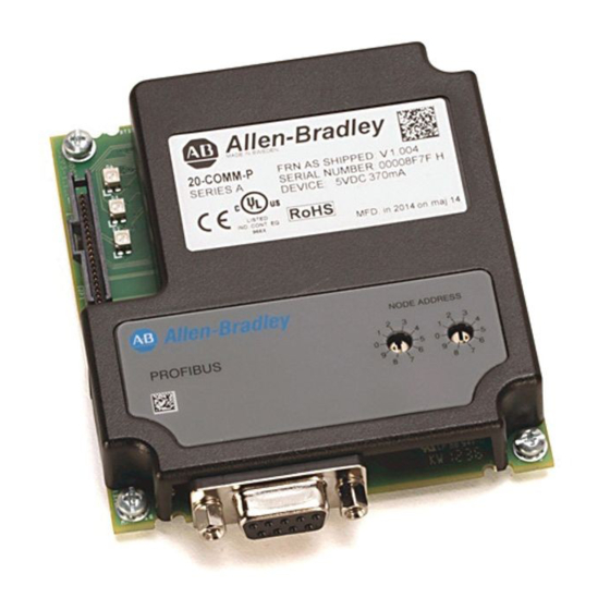
Profibus Connector A 9-pin, female D-sub connector to connect to the network. Node Address Switches to set the node address. See Setting the Node Address Switches Switches on page 2-2. PowerFlex 20-COMM-P Profibus Adapter User Manual Publication 20COMM-UM006B-EN-P... -
Page 12: Features
• PowerFlex 700S drives with Phase I or Phase II control • PowerFlex 700L drives with 700 vector control or 700S control • PowerFlex Digital DC drives • SMC™ Flex smart motor controllers • SMC-50 smart motor controllers PowerFlex 20-COMM-P Profibus Adapter User Manual Publication 20COMM-UM006B-EN-P... -
Page 13: Required Equipment
• Requesting a DVD at http://www.ab.com/onecontact/controllers/ micro800/ Your local distributor may also have copies of the DVD available. Connected Components Workbench software cannot be used to configure SCANport-based drives or Bulletin 160 drives. PowerFlex 20-COMM-P Profibus Adapter User Manual Publication 20COMM-UM006B-EN-P... - Page 14 It is highly recommended that you periodically check for and install the latest update. 1203-USB Serial Converter or 1203-SSS Serial Converter with firmware revision 3.001 or later Profibus configuration software Controller configuration software PowerFlex 20-COMM-P Profibus Adapter User Manual Publication 20COMM-UM006B-EN-P...
-
Page 15: Safety Precautions
There are many variables and requirements with any application. Rockwell Automation does not assume responsibility or liability (to include intellectual property liability) for actual use of the examples shown in this publication. PowerFlex 20-COMM-P Profibus Adapter User Manual Publication 20COMM-UM006B-EN-P... -
Page 16: Quick Start
Chapter Using Explicit Messaging • Control the connected drive, via the adapter, by using I/O. • Monitor or configure the drive using explicit messages. PowerFlex 20-COMM-P Profibus Adapter User Manual Publication 20COMM-UM006B-EN-P... -
Page 17: Preparing For An Installation
Important: New settings for some adapter parameters are recognized only when power is applied to the adapter or it is reset. After you change parameter settings, cycle power or reset the adapter. PowerFlex 20-COMM-P Profibus Adapter User Manual Publication 20COMM-UM006B-EN-P... -
Page 18: Setting The Node Address Switches
7-4) with any of the following drive configuration tools: • PowerFlex HIM • Connected Components Workbench software, version 1.02 or later • DriveExplorer software, version 2.01 or later • DriveExecutive software, version 3.01 or later PowerFlex 20-COMM-P Profibus Adapter User Manual Publication 20COMM-UM006B-EN-P... -
Page 19: Connecting The Adapter To The Drive
– On a PowerFlex 700, PowerFlex 700H, or PowerFlex 700S drive, mount the adapter on the drive using the four captive screws. Important: Tighten all screws to properly ground the adapter. Recommended torque is 0.9 N•m (8.0 lb•in). PowerFlex 20-COMM-P Profibus Adapter User Manual Publication 20COMM-UM006B-EN-P... - Page 20 PowerFlex 700H Frames 9 and Larger PowerFlex 700S Frames 9 and Larger Item Description 15.24 cm (6 in.) Internal Interface cable DPI Connector Profibus connector 2.54 cm (1 in.) Internal Interface cable PowerFlex 20-COMM-P Profibus Adapter User Manual Publication 20COMM-UM006B-EN-P...
- Page 21 After tightening the screw, verify continuity exists between the head of the screw and drive ground. PowerFlex 700H Frames 9 and Larger PowerFlex 700S Frames 9 and Larger (Adapter mounts behind HIM panel.) PowerFlex 20-COMM-P Profibus Adapter User Manual Publication 20COMM-UM006B-EN-P...
-
Page 22: Connecting The Adapter To The Network
Phoenix Subcon and ENRI Connectors Phoenix Subcon Connector ENRI Connector Figure 2.5 PROFIBUS Connector Network Diagram Table 2.A Adapter PROFIBUS Connector Pin Layout Terminal Signal Function Housing Shield — Not connected — Not connected — PowerFlex 20-COMM-P Profibus Adapter User Manual Publication 20COMM-UM006B-EN-P... -
Page 23: Node Termination
Profibus node connectors, such as the Phoenix Subcon Plus M1 (Part #2761826), can be configured as a terminating connector by adding resistors (see Figure 2.6). Figure 2.6 Phoenix Subcon Plus M1 Connection for Terminating Resistors PowerFlex 20-COMM-P Profibus Adapter User Manual Publication 20COMM-UM006B-EN-P... -
Page 24: Applying Power
2.7) after power has been applied. Possible start-up status indications are shown in Table 2.B. Figure 2.7 Drive and Adapter Status Indicators (location on drive may vary) PORT NET A NET B PowerFlex 20-COMM-P Profibus Adapter User Manual Publication 20COMM-UM006B-EN-P... - Page 25 2. If hard-wired discrete digital inputs are not used to control the drive, verify that unused digital input drive Parameters 361 - [Dig In1 Sel] and 362 - [Dig In2 Sel] are set to ‘0’ (Not Used). PowerFlex 20-COMM-P Profibus Adapter User Manual Publication 20COMM-UM006B-EN-P...
- Page 26 This ensures that any Reference commanded from the network can be monitored by using drive Parameter 002 - [Commanded Speed]. If a problem occurs, this verification step provides the diagnostic capability to determine whether the drive/adapter or the network is the cause. PowerFlex 20-COMM-P Profibus Adapter User Manual Publication 20COMM-UM006B-EN-P...
-
Page 27: Chapter 3 Configuring The Adapter
(installed with the software) DriveExplorer software, http://www.ab.com/drives/driveexplorer, or version 2.01 or later DriveExplorer online help (installed with the software) DriveExecutive software, http://www.ab.com/drives/drivetools, or version 3.01 or later DriveExecutive online help (installed with the software) PowerFlex 20-COMM-P Profibus Adapter User Manual Publication 20COMM-UM006B-EN-P... - Page 28 NOTE: All configuration procedures throughout this chapter use the PowerFlex 7-Class LCD HIM to access parameters in the adapter and show example LCD HIM screens. TIP: When using a PowerFlex 20-HIM-A6 or 20-HIM-C6S HIM, see its User Manual, publication 20-HIM-UM001. PowerFlex 20-COMM-P Profibus Adapter User Manual Publication 20COMM-UM006B-EN-P...
-
Page 29: Setting The Node Address
When using Datalinks, up to 8 drive [Data In xx] parameters (300…307) and/or up to 8 [Data Out xx] parameters (310…317) must be assigned to point to the appropriate drive parameters for your PowerFlex 20-COMM-P Profibus Adapter User Manual Publication 20COMM-UM006B-EN-P... -
Page 30: Setting A Fault Action
(Parameters 13 - [Flt Cfg Logic] through 22 - [Flt Cfg D2 In]). Port 5 Device Port 5 Device 20-COMM-P 20-COMM-P Parameter #: 9 Parameter #: 10 Comm Flt Action Idle Flt Action Fault Fault PowerFlex 20-COMM-P Profibus Adapter User Manual Publication 20COMM-UM006B-EN-P... -
Page 31: Resetting The Adapter
After performing a Set Defaults, enter ‘1’ (Reset Module) so that the new values take effect. The value of this parameter is restored to ‘0’ (Ready) after the adapter is reset. PowerFlex 20-COMM-P Profibus Adapter User Manual Publication 20COMM-UM006B-EN-P... -
Page 32: Viewing The Adapter Status Using Parameters
DriveExplorer Lite or Full software, or the built-in update capability of DriveExecutive software. When updating firmware through a direct serial connection from a computer to a drive, you can use the same Allen-Bradley software tools described above, or you can use HyperTerminal software set to the X-modem protocol. -
Page 33: Chapter 4 Configuring The Profibus Scanner
Figure 4.1. Figure 4.1 Example Profibus Network COMM LED SYS LED Config Port Front Label PROFIBUS Port Station 0 PROFIBUS Network PowerFlex 70 Drive PowerFlex 70 Drive Station 1 Station 2 PowerFlex 20-COMM-P Profibus Adapter User Manual Publication 20COMM-UM006B-EN-P... -
Page 34: Sst Profibus Configuration Software Tool
Additional data files, such as the 20-COMM-P adapter GSD file, need to be added to configure the 20-COMM-P adapter in the scanner. 1. Click the ‘New Device’ icon to add the GSD file to the software library tool. PowerFlex 20-COMM-P Profibus Adapter User Manual Publication 20COMM-UM006B-EN-P... - Page 35 4. In the treeview in the Device Library pane, click the ‘+’ sign of the Slaves folder. The software tool will automatically create an Allen-Bradley sub-folder (in the Slaves folder) if it does not already exist. The 20-COMM-P is now shown in the library and the software tool is now ready to configure a 20-COMM-P adapter on a Profibus network.
-
Page 36: Configuring The Sst-Pfb-Slc Profibus Scanner
Available DP masters are displayed in this sub-folder. 2. In the Device Library pane treeview, click the Slaves folder ‘+’ sign and then the Allen-Bradley sub-folder ‘+’ sign to display the available DP slaves or the 20-COMM-P slave. 3. In the Device Library pane treeview under the Masters folder, double-click ‘SST-PFB-SLC MASTER’... - Page 37 The scanner will appear in the network configuration pane as shown below. 7. Double-click the scanner in the network configuration pane. 8. In the Device Library pane treeview under the Allen-Bradley folder, double-click the ‘20_COMM_P’. The 20-COMM-P window appears. A user-defined name and description can be given to this 20-COMM-P.
- Page 38 The ‘Ctrl/Stat & Ref/Fdbk (2+2 bytes)’ module has been added. Station 1 will also be configured to use Datalinks A1 and A2. The PowerFlex 70 uses 16-bit Datalinks. 12. Click Add to continue adding modules. PowerFlex 20-COMM-P Profibus Adapter User Manual Publication 20COMM-UM006B-EN-P...
- Page 39 Station 1 will also be configured to use Datalinks B1 and B2. The PowerFlex 70 uses 16-bit Datalinks. 14. Click Add to continue adding modules. 15. Select ‘Datalink B (2x2 bytes)’ as shown below and click OK. PowerFlex 20-COMM-P Profibus Adapter User Manual Publication 20COMM-UM006B-EN-P...
- Page 40 The ‘Datalink C’ module has been added. Station 1 will also be configured to use Datalinks D1 and D2. The PowerFlex 70 uses 16-bit Datalinks. 18. Click Add to continue adding modules. PowerFlex 20-COMM-P Profibus Adapter User Manual Publication 20COMM-UM006B-EN-P...
- Page 41 21. Select ‘Parameter Access’ as shown below and click OK. The ‘Parameter Access’ module has been added. Settings can be chosen to map Station modules to SLC master addresses. In our example, M1/M0 files are used for Input/Output. PowerFlex 20-COMM-P Profibus Adapter User Manual Publication 20COMM-UM006B-EN-P...
- Page 42 23. In the SLC Address Tab window, select Datalink A. Datalink A is at word 2 in the M1/M0 files. 24. In the SLC Address Tab window, select Datalink B. Datalink B is at word 4 in the M1/M0 files. PowerFlex 20-COMM-P Profibus Adapter User Manual Publication 20COMM-UM006B-EN-P...
- Page 43 Parameter Access starts at word 10 in the M1/M0 files. It uses 4 words (10…13). 28. Click OK when finished. Station 1 is now displayed in the network configuration pane under its SLC master. PowerFlex 20-COMM-P Profibus Adapter User Manual Publication 20COMM-UM006B-EN-P...
- Page 44 ‘Load Configuration’. If a minimum cycle time attention window pops up, click OK to continue. After the configuration has been loaded into the scanner, ‘Configured Program’ will be displayed in the message window. PowerFlex 20-COMM-P Profibus Adapter User Manual Publication 20COMM-UM006B-EN-P...
-
Page 45: Gsd Diagnostic Messages
The Ctrl/Stat & Ref/Fdbk module must always be used and placed first in the configuration. Module used more than once A GSD module has been used more than once. Not supported module An unrecognized module has been used in the configuration. PowerFlex 20-COMM-P Profibus Adapter User Manual Publication 20COMM-UM006B-EN-P... - Page 46 4-14 Configuring the Profibus Scanner Notes: PowerFlex 20-COMM-P Profibus Adapter User Manual Publication 20COMM-UM006B-EN-P...
-
Page 47: About I/O Messaging
Scanner, discuss how to configure the adapter and controller on the network for these options. The Glossary defines the different options. This chapter discusses how to use I/O after you have configured the adapter and controller. PowerFlex 20-COMM-P Profibus Adapter User Manual Publication 20COMM-UM006B-EN-P... -
Page 48: Understanding The I/O Image
Data Out D1 9 Datalink Out D2 Data Out D2 10 Parameter Access Word 1 Message 11 Parameter Access Word 2 Handler 12 Parameter Access Word 3 13 Parameter Access Word 4 PowerFlex 20-COMM-P Profibus Adapter User Manual Publication 20COMM-UM006B-EN-P... - Page 49 Data Out D1 9 Datalink Out D2 Data Out D2 10 Parameter Access Word 1 Message 11 Parameter Access Word 2 Handler 12 Parameter Access Word 3 13 Parameter Access Word 4 PowerFlex 20-COMM-P Profibus Adapter User Manual Publication 20COMM-UM006B-EN-P...
-
Page 50: Using Logic Command/Status
The size of the Reference/Feedback is determined by the drive and can be displayed with adapter Parameter 06 - [Ref/Fdbk Size]. Size Valid Values 16-bit -32768 to 32767 32-bit -2147483648 to 2147483647 PowerFlex 20-COMM-P Profibus Adapter User Manual Publication 20COMM-UM006B-EN-P... - Page 51 Using the parameter 82 default value, speed Reference/Feedback scaling is: 0…32767 = 0…60.0 Hz. If parameter 82 - [Maximum Speed] is changed to 90 Hz, then: 90 Hz = 32767 Speed Feedback uses the same scaling as the speed Reference. PowerFlex 20-COMM-P Profibus Adapter User Manual Publication 20COMM-UM006B-EN-P...
-
Page 52: Using Datalinks
• Each set of Datalink parameters in a PowerFlex drive can be used by only one adapter. If more than one adapter is connected to a single drive, multiple adapters cannot use the same Datalink. PowerFlex 20-COMM-P Profibus Adapter User Manual Publication 20COMM-UM006B-EN-P... - Page 53 PowerFlex 70 drive, both Datalink A1 Out (Parameter 310) and Datalink A2 Out (Parameter 311) are set to ‘10’. Datalink A1 Out will contain the least significant word (LSW) and Datalink A2 Out will contain the most significant word (MSW). PowerFlex 20-COMM-P Profibus Adapter User Manual Publication 20COMM-UM006B-EN-P...
-
Page 54: Slc Controller Example Ladder Logic Program Information
• Send a Logic Command to control the drive (for example, start, stop). • Send a Reference to the drive and receive Feedback from the drive. • Send/receive Datalink data to/from the drive. • Access Parameters (described in Chapter PowerFlex 20-COMM-P Profibus Adapter User Manual Publication 20COMM-UM006B-EN-P... - Page 55 TIP: Data In parameters are inputs into the drive that come from controller outputs (for example, data to write to a drive parameter). Data Out parameters are outputs from the drive that go to controller inputs (for example, data to read a drive parameter). PowerFlex 20-COMM-P Profibus Adapter User Manual Publication 20COMM-UM006B-EN-P...
- Page 56 N10:8 N10:22 Datalink D1 N10:9 N10:23 Datalink D2 N10:10 N10:24 Parameter Access Word 1 N10:11 N10:25 Parameter Access Word 2 N10:12 N10:26 Parameter Access Word 3 N10:13 N10:27 Parameter Access Word 4 PowerFlex 20-COMM-P Profibus Adapter User Manual Publication 20COMM-UM006B-EN-P...
- Page 57 PowerFlex 70/700 drives. See Appendix C to view details. The definition of the bits in these words may vary if you are using a different DPI drive. See the documentation for your drive. PowerFlex 20-COMM-P Profibus Adapter User Manual Publication 20COMM-UM006B-EN-P...
-
Page 58: Slc Ladder Logic Example Main Program
The Scanner is configured for 28 bytes (14 words) of inputs for each drive. Two drives require 48 bytes (28 words). Read the drives data from the Profibus scanner. SST Scanner Read Data Word #0 0002 Copy File Source #M1:1.0 Dest #N9:0 Length PowerFlex 20-COMM-P Profibus Adapter User Manual Publication 20COMM-UM006B-EN-P... - Page 59 For Ladder 3 Station 1 Drive Logic, see Figure 5.2 (Example SLC Ladder Logic Station 1 Program). For Ladder 4 Station 2 Drive Logic, see Figure 5.3 (Example SLC Ladder Logic Station 2 Program). PowerFlex 20-COMM-P Profibus Adapter User Manual Publication 20COMM-UM006B-EN-P...
- Page 60 XMIT Data Word 0 Swap 0008 Source #N21:0 Length Write the drives data to the Profibus scanner. SST Scanner Write Data Word 0 0009 Copy File Source #N21:0 Dest #M0:1.0 Length 0010 PowerFlex 20-COMM-P Profibus Adapter User Manual Publication 20COMM-UM006B-EN-P...
-
Page 61: Slc Ladder Logic Example Station 1 Program
PowerFlex 70 Speed Ref A Sel (Pr.90) needs to be set to 'DPI Port 5'. N19:1 is controlled elsewhere in the user program. Station 1 Speed Reference Move 0006 Source N19:1 8192 < Dest N20:1 8192 < PowerFlex 20-COMM-P Profibus Adapter User Manual Publication 20COMM-UM006B-EN-P... - Page 62 Station 1 Datalink B1 Datalink B1 (Pr. 302) set to Jog Speed (Pr. 100). N19:4 is controlled elsewhere in the user program. Station 1 Datalink B1 Write 0009 Move Source N19:4 100< Dest N20:4 100< PowerFlex 20-COMM-P Profibus Adapter User Manual Publication 20COMM-UM006B-EN-P...
- Page 63 Datalink C2 (Pr. 305) set to Preset Speed 2 (Pr. 102). N19:7 is controlled elsewhere in the user program. Station 1 Datalink C2 Write 0012 Move Source N19:7 200< Dest N20:7 200< PowerFlex 20-COMM-P Profibus Adapter User Manual Publication 20COMM-UM006B-EN-P...
- Page 64 Source N19:9 400< Dest N20:9 400< The Station 1 program can either end here or, if Explicit Messaging is needed, Parameter Protocol logic can be added (see Figure 6.5 on page 6-10). PowerFlex 20-COMM-P Profibus Adapter User Manual Publication 20COMM-UM006B-EN-P...
-
Page 65: Slc Ladder Logic Example Station 2 Program
Logic Command Command CLEAR FAULTS B3:21 N20:14 0003 Station 2 Station 2 Reverse Logic Command Command FORWARD B3:21 N20:14 0004 Station 2 Station 2 Logic Command Reverse Command REVERSE B3:21 N20:14 0005 PowerFlex 20-COMM-P Profibus Adapter User Manual Publication 20COMM-UM006B-EN-P... - Page 66 Datalink A2 (Pr. 301) set to Deceleration Time 1 (Pr. 142). N19:17 is controlled elsewhere in the user program. Station 2 Datalink A2 Write 0008 Move Source N19:17 50< Dest N20:17 50< PowerFlex 20-COMM-P Profibus Adapter User Manual Publication 20COMM-UM006B-EN-P...
- Page 67 Datalink C1 (Pr. 304) set to Preset Speed 1 (Pr. 101). N19:20 is controlled elsewhere in the user program. Station 2 Datalink C1 Write 0011 Move Source N19:20 100< Dest N20:20 100< PowerFlex 20-COMM-P Profibus Adapter User Manual Publication 20COMM-UM006B-EN-P...
- Page 68 Source N19:23 400< Dest N20:23 400< The Station 2 program can either end here or, if Explicit Messaging is needed, Parameter Protocol logic can be added (see Figure 6.6 on page 6-12). PowerFlex 20-COMM-P Profibus Adapter User Manual Publication 20COMM-UM006B-EN-P...
-
Page 69: Chapter 6 Using Explicit Messaging
Explicit Messages to write parameter data to NVS. Datalinks do not write to NVS and should be used for frequently changed parameters. Refer to Chapter 5 for information about the I/O Image, using Logic Command/Status, Reference/Feedback, and Datalinks. PowerFlex 20-COMM-P Profibus Adapter User Manual Publication 20COMM-UM006B-EN-P... -
Page 70: About Explicit Messaging
The Explicit Message is complete. For information on the maximum number of Explicit Messages that can be executed at a time, see the user manual for the scanner and/or controller that is being used. PowerFlex 20-COMM-P Profibus Adapter User Manual Publication 20COMM-UM006B-EN-P... -
Page 71: Parameter Protocol
(32-bit low word/8-bit & 16-bit value) (32-bit low word/8-bit & 16-bit value) Parameter Message Request on page 6-4 Parameter Message Response on page 6-5 for a description of the data that is required in each word. PowerFlex 20-COMM-P Profibus Adapter User Manual Publication 20COMM-UM006B-EN-P... - Page 72 PVA - Parameter Value (32-bit low word or 8-bit and 16-bit word) The parameter value; if the parameter is 32 bits, the least significant bytes are placed here. If the parameter is 16-bit or lower, the entire result is placed in this word. PowerFlex 20-COMM-P Profibus Adapter User Manual Publication 20COMM-UM006B-EN-P...
- Page 73 Parameter does not exist (parameter number is greater than the maximum number of parameters) Data value out of range (Set value is out of range) State conflict (parameter is not changeable while the product is in an operating state) PowerFlex 20-COMM-P Profibus Adapter User Manual Publication 20COMM-UM006B-EN-P...
- Page 74 Value Message Address Word (Hex) Description Request N20:10 108C 1000 Hex = Read 8C Hex = 140 Dec (Par. 140) N20:11 DPI Port 0 (DPI Host) N20:12 Not Used N20:13 Not Used PowerFlex 20-COMM-P Profibus Adapter User Manual Publication 20COMM-UM006B-EN-P...
- Page 75 (DPI Port #). N10:12 Parameter value high word N10:13 518E Parameter value low word The high and low word 1B518E Hex = 1,790,350 decimal, which equates to 179.0350 hours (fixed decimal point). PowerFlex 20-COMM-P Profibus Adapter User Manual Publication 20COMM-UM006B-EN-P...
- Page 76 2000 Hex = Change parameter value (word) 65 Hex = 101 Dec (Par. 101) N20:11 DPI Port 0 (DPI Host) N20:12 Not Used N20:13 64 Hex = 100 Dec = 10.0 Hz PowerFlex 20-COMM-P Profibus Adapter User Manual Publication 20COMM-UM006B-EN-P...
- Page 77 Confirms Par. Number of the request (‘F’) N10:11 Confirms Par. Access Word 2 of the request N10:12 Confirms Par. Access Word 3 of the request N10:13 Confirms Par. Access Word 4 of the request PowerFlex 20-COMM-P Profibus Adapter User Manual Publication 20COMM-UM006B-EN-P...
-
Page 78: Slc Ladder Example Station 1 Parameter Protocol
Dest N20:10 0< 0< PCA Word RC bit 0 bit 0 N7:10 N20:10 PCA Word RC bit 1 bit 1 N7:10 N20:10 IND Word (Subindex) Copy File Source #N7:12 Dest #N20:11 Length PowerFlex 20-COMM-P Profibus Adapter User Manual Publication 20COMM-UM006B-EN-P... - Page 79 Copy File Source A N10:10 Source #N10:10 0< Dest #N7:20 Source B Length 0< Station 1 PCA Word Move Source 0< Dest N20:10 0< Station 1 Par Prot Messaging Request B3:19 0018 PowerFlex 20-COMM-P Profibus Adapter User Manual Publication 20COMM-UM006B-EN-P...
-
Page 80: Slc Ladder Example Station 2 Parameter Protocol
Dest N20:24 0< 0< PCA Word RC bit 0 bit 0 N7:30 N20:24 PCA Word RC bit 1 bit 2 N7:30 N20:24 IND Word (Subindex) Copy File Source #N7:32 Dest #N20:25 Length PowerFlex 20-COMM-P Profibus Adapter User Manual Publication 20COMM-UM006B-EN-P... - Page 81 Copy File Source A N10:24 Source #N10:24 0< Dest #N7:40 Source B Length 0< Station 2 PCA Word Move Source 0< Dest N20:24 0< Station 2 Par Prot Messaging Request B3:19 0018 PowerFlex 20-COMM-P Profibus Adapter User Manual Publication 20COMM-UM006B-EN-P...
- Page 82 6-14 Using Explicit Messaging Notes: PowerFlex 20-COMM-P Profibus Adapter User Manual Publication 20COMM-UM006B-EN-P...
-
Page 83: Chapter 7 Troubleshooting
Location on drive may vary. Item Status Indicator Description Page PORT DPI Connection Status Adapter Status NET A Profibus Network Status NET B (only on drive cover Not used for Profibus — PowerFlex 20-COMM-P Profibus Adapter User Manual Publication 20COMM-UM006B-EN-P... -
Page 84: Port Status Indicator
• Configure the adapter for the program in the controller. • Normal behavior if no DPI I/O is enabled. Steady Green The adapter is operational and transferring No action required. I/O data to a controller. PowerFlex 20-COMM-P Profibus Adapter User Manual Publication 20COMM-UM006B-EN-P... -
Page 85: Net A Status Indicator
Note that a 16-bit value will be sent as the Most Significant Word of the 32-bit field. Common Logic Sts The present value of the Common Logic Status being received from the drive by this adapter. PowerFlex 20-COMM-P Profibus Adapter User Manual Publication 20COMM-UM006B-EN-P... - Page 86 The buffer size of active I/O image (Profibus size) in bytes. Switch 0 The present value of the adapter node address Switch 0 (ones digit). Switch 1 The present value of the adapter node address Switch 1 (tens digit). PowerFlex 20-COMM-P Profibus Adapter User Manual Publication 20COMM-UM006B-EN-P...
-
Page 87: Viewing And Clearing Events
A message pops up to confirm that you want to clear the message or queue. 5. Press the (Enter) key to confirm your request. If Clr Event Queue was selected, all event queue entries display ‘No Event’. PowerFlex 20-COMM-P Profibus Adapter User Manual Publication 20COMM-UM006B-EN-P... - Page 88 Many events in the event queue occur under normal operation. If you encounter unexpected communication problems, the events can help you or Allen-Bradley personnel troubleshoot the problem. The following events can appear in the event queue. Table 7.B Adapter Events...
-
Page 89: Appendix A Specifications
If the adapter is not going to be installed for a period of time, it must be stored in an area where it is not exposed to a corrosive atmosphere. PowerFlex 20-COMM-P Profibus Adapter User Manual Publication 20COMM-UM006B-EN-P... -
Page 90: Regulatory Compliance
CAN / CSA C22.2 No. 14-M91 EN50178 and EN61800-3 CTick EN61800-3 NOTE: This is a product of category C3 according to IEC 61800-3. It is not intended for operation in a domestic environment. PowerFlex 20-COMM-P Profibus Adapter User Manual Publication 20COMM-UM006B-EN-P... -
Page 91: About Parameter Numbers
Read/Write ‘00’. (Updates Parameter 04 - [P-DP Addr Actual] Reset Required: Yes after reset). [P-DP Addr Actual] Minimum: Maximum: Displays the actual network node address used by Type: Read Only the adapter. PowerFlex 20-COMM-P Profibus Adapter User Manual Publication 20COMM-UM006B-EN-P... - Page 92 When commissioning the drive, verify that your system responds correctly to various situations (for example, a disconnected cable). PowerFlex 20-COMM-P Profibus Adapter User Manual Publication 20COMM-UM006B-EN-P...
- Page 93 (Send Flt Cfg) and the controller is idle. The bit definitions depend on the product to which the adapter is connected. See Appendix C or the documentation for the drive being used. PowerFlex 20-COMM-P Profibus Adapter User Manual Publication 20COMM-UM006B-EN-P...
- Page 94 [P-DP State] Values: 0 = WAIT_PRM 1 = WAIT CFG Displays the state of the Profibus controller. 2 = DATA_EX 3 = ERROR Type: Read Only PowerFlex 20-COMM-P Profibus Adapter User Manual Publication 20COMM-UM006B-EN-P...
-
Page 95: Appendix C Logic Command/Status Words
This Reference Select does not function if a digital input (parameters 361…366) is programmed for ‘Speed Sel 1, 2, or 3’ (option 15, 16, or 17). Note that Reference Select is ‘Exclusive Ownership’ – see drive User Manual for more information. PowerFlex 20-COMM-P Profibus Adapter User Manual Publication 20COMM-UM006B-EN-P... - Page 96 1011 = DPI 3 Manual 1100 = DPI 4 Manual 1101 = DPI 5 Manual 1110 = DPI 6 Manual 1111 = Jog Ref See ‘Owners’ in drive User Manual for more information. PowerFlex 20-COMM-P Profibus Adapter User Manual Publication 20COMM-UM006B-EN-P...
- Page 97 A Not Stop condition (logic bit 0 = 0, logic bit 8 = 0, and logic bit 9 = 0) must first be present before a 1 = Start condition starts the drive. To perform this command, the value must switch from ‘0’ to ‘1’. PowerFlex 20-COMM-P Profibus Adapter User Manual Publication 20COMM-UM006B-EN-P...
- Page 98 1= At Setpoint Speed Enable 0 = Not Enabled 1 = Enabled See Parameter 304 - [Limit Status] in the PowerFlex 700S drive User Manual for a description of the limit status conditions. PowerFlex 20-COMM-P Profibus Adapter User Manual Publication 20COMM-UM006B-EN-P...
-
Page 99: Powerflex Digital Dc Drives
This Reference Select does not function if a digital input (parameters 133…144) is programmed for ‘Speed Sel 1, 2, or 3’ (option 17, 18, or 19). Note that Reference Select is ‘Exclusive Ownership’ – see drive User Manual for more information. PowerFlex 20-COMM-P Profibus Adapter User Manual Publication 20COMM-UM006B-EN-P... - Page 100 1010 = DPI 2 Manual 1011 = DPI 3 Manual 1100 = DPI 4 Manual 1101 = DPI 5 Manual 1110 = Reserved 1111 = Jog Ref See ‘Owners’ in drive User Manual for more information. PowerFlex 20-COMM-P Profibus Adapter User Manual Publication 20COMM-UM006B-EN-P...
- Page 101 CAN is a serial bus protocol on which DPI is based. Connected Components Workbench Software The recommended tool for monitoring and configuring Allen-Bradley products and network communication adapters. It can be used on computers running various Microsoft operating systems. You can obtain a free copy of Connect Components Workbench software at http://www.ab.com/support/...
- Page 102 PowerFlex 7-Class drive is a DPI product. In this manual, a DPI product is also referred to as ‘drive’ or ‘host’. DriveExplorer Software A tool for monitoring and configuring Allen-Bradley products and network communication adapters. It can be used on computers running various Microsoft Windows operating systems. DriveExplorer software, version 3.xx or later, can be used to configure this adapter and connected drive.
- Page 103 This software suite provides a family of tools, including DriveExecutive software (version 3.01 or later), that you can use to program, monitor, control, troubleshoot, and maintain Allen-Bradley products. DriveTools SP software can be used with PowerFlex 750-Series, PowerFlex 7-Class, and PowerFlex 4-Class drives, and also legacy drives that implement the SCANport communication interface.
- Page 104 NVS so that they are not lost when the device loses power. NVS is sometimes called ‘EEPROM’. Parameter Messaging Parameter Messaging is used to configure, monitor, and diagnose devices over the Profibus network. PowerFlex 20-COMM-P Profibus Adapter User Manual Publication 20COMM-UM006B-EN-P...
- Page 105 PowerFlex 7-Class (Architecture Class) Drives The Allen-Bradley PowerFlex 7-Class family of drives supports DPI and, at the time of publication, includes the PowerFlex 70, PowerFlex 700, PowerFlex 700H, PowerFlex 700S, PowerFlex 700L, and PowerFlex 7000.
- Page 106 Logic Command, Reference, and Datalink data. If the drive was running and using the Reference from the adapter, it will stay running but at zero Reference. PowerFlex 20-COMM-P Profibus Adapter User Manual Publication 20COMM-UM006B-EN-P...
-
Page 107: Index
Comm Flt Action parameter, B-2 DriveTools SP software, G-3 commissioning the adapter, 2-1 communications module, see adapter compatible products, 1-2 EEPROM, see Nonvolatile Storage (NVS) components of the adapter, 1-1 environmental specifications, A-1 PowerFlex 20-COMM-P Profibus Adapter User Manual Publication 20COMM-UM006B-EN-P... - Page 108 G-3 related documentation, P-2 LCD model, 3-2 website, P-2 LED model, 3-2 Master, G-4 hold last mechanical dimensions, A-1 configuring the adapter for, 3-4 definition, G-4 messages, see explicit messaging or I/O PowerFlex 20-COMM-P Profibus Adapter User Manual Publication 20COMM-UM006B-EN-P...
- Page 109 7-2 to 7-3 compatible with adapter, 1-2 understanding, 7-1 definition, G-5 switches to set node address, 2-2 HIM, 3-2 installing adapter on, 2-3 preparing for an installation, 2-1 technical support, P-2 processor, see controller PowerFlex 20-COMM-P Profibus Adapter User Manual Publication 20COMM-UM006B-EN-P...
- Page 110 Connected Components Workbench software, G-1 DriveExecutive software, G-3 DriveExplorer software, G-2 DriveTools SP software, G-3 Profibus network, G-5 related documentation, P-2 wiring, see cables zero data configuring the adapter for, 3-4 definition, G-6 PowerFlex 20-COMM-P Profibus Adapter User Manual Publication 20COMM-UM006B-EN-P...
- Page 112 Rockwell Automation Support Rockwell Automation provides technical information on the Web to assist you in using its products. http://www.rockwellautomation.com/support you can find technical and application notes, sample code, and links to software service packs. You can also visit our Support Center at https://rockwellautomation.custhelp.com/ for software updates, support chats and forums, technical information, FAQs, and to sign up for product notification updates.
Need help?
Do you have a question about the PowerFlex 20-COMM-P and is the answer not in the manual?
Questions and answers