
Related Manuals for Allen-Bradley 2100-ENET Series


Summary of Contents for Allen-Bradley 2100-ENET Series
- Page 1 User Manual CENTERLINE 2100 Motor Control Centers EtherNet/IP Network Adapter Catalog Numbers 2100-ENET Series A FRN 1.XXX...
- Page 2 Identifies information that is critical for successful application and understanding of the product. Allen-Bradley, Rockwell Software, Rockwell Automation, E3 Plus, RSLogix, MicroLogix, ControlFLASH, Stratix 6000, RSLinx, CompactLogix, ControlLogix, DeviceLogix, Logix5000, PanelView, PLC-5, SLC, TechConnect, CENTERLINE, Studio 5000, and IntelliCENTER are trademarks of Rockwell Automation, Inc.
-
Page 3: Table Of Contents
Table of Contents Preface Additional Resources ..........5 Rockwell Automation Support . - Page 4 Table of Contents Using the RSLogix 5000 Generic Profile (all versions) ... 35 Logix Controller I/O Messaging ....... 35 Limitations When Using PLC-5, SLC 500, or MicroLogix 1100 or MicroLogix 1400 Controllers .
-
Page 5: Additional Resources
You can view or download publications at http:/www.rockwellautomation.com/literature/. To order paper copies of technical documentation, contact your local Allen-Bradley distributor or Rockwell Automation sales representative. For information such as firmware updates or answers to product-related questions, go to the Support website at http://www.rockwellautomation.com/rockwellautomation/support. -
Page 6: Rockwell Automation Support
Preface Rockwell Automation Rockwell Automation, Inc. offers support services worldwide, with over 75 sales/ support offices, over 500 authorized distributors, and over 250 authorized Support systems integrators located through the United States alone. In addition, Rockwell Automation, Inc. representatives are in every major country in the world. -
Page 7: Studio 5000 Environment
Preface • Screen shots in this manual were taken from the following software packages. Your screen can appear slightly different if your version of the software is not the same: • RSLinx software, version 2.51 • RSLogix 5 software, version 7.20 •... - Page 8 Preface Notes: Rockwell Automation Publication 2100-UM006A-EN-P - July 2013...
-
Page 9: Adapter Components
The features of the adapter include the following: • Can be panel-mounted or DIN Rail Mounted with PN-107433 available through your Allen-Bradley distributor. The adapter can be mounted with either two or four screws in any orientation necessary. • Grounding is provided through the housing. Grounding is to be provided by one of the panel mounting holes. -
Page 10: Compatible Products
Chapter 1 Getting Started • Compatibility with IntelliCENTER software for parameter configuration of the end device. A Bootstrap Protocol (BOOTP) server can be used to configure the network address for the adapter. • Status indicators that report the status of the end device communication, the adapter, and network. -
Page 11: Safety Precautions
Getting Started Chapter 1 Safety Precautions Read the following safety precautions carefully. ATTENTION: Risk of injury or equipment damage exists. If the adapter is transmitting control I/O to the end device, the end device can fault when you reset the adapter. Determine how your end device responds before resetting an adapter. -
Page 12: Quick Start
Chapter 1 Getting Started Quick Start This section is provided to help experienced users quickly start using the adapter. If you are unsure how to complete a step, refer to the referenced chapter. Step Action Refer to Review the safety precautions for the adapter. Throughout This Manual Verify that the end device is properly installed. -
Page 13: Prepare For An Installation
Chapter Install the Adapter This chapter provides instructions for installing the adapter. Topic Page Prepare for an Installation Connect the Adapter to the End Device Connect the Adapter to the Network Apply Power Commission the Adapter Prepare for an Installation Before installing the adapter, refer to these guidelines: •... -
Page 14: Connect The Adapter To The End Device
Chapter 2 Install the Adapter IGMP snooping constrains the flooding of multicast traffic by dynamically configuring switch ports so that multicast traffic is forwarded only to ports associated with a particular IP multicast group. Switches that support IGMP snooping (managed switches) learn which ports have devices that are part of a particular multicast group and forward only the multicast packets to the ports that are part of the multicast group. -
Page 15: Connect The Adapter To The Network
Install the Adapter Chapter 2 Connect the Adapter to the Follow these steps to connect the adapter to the network. Network 1. Connect one end of an Ethernet cable to the network. See following graphic for an example of wiring to an EtherNet/IP network. -
Page 16: Commission The Adapter
Chapter 2 Install the Adapter After installing the adapter and applying power, refer to Table 8 on page 58 for a description of the status indicators. Commission the Adapter To commission the adapter, you must set a unique IP address on the network. (Refer to the Glossary for details about IP addresses.) After installing the adapter... -
Page 17: Configuration Tools
Chapter Configure the Adapter This chapter provides instructions and information for setting up the adapter. Topic Page Configuration Tools Using BOOTP Set the Data Rate Set the I/O Configuration Set a Fault Action Reset the Adapter Update the Adapter For a list of E3 Plus or 825-P parameters, refer to the appropriate user manual. For definitions of terms in this chapter, refer to the Glossary. -
Page 18: Configure The Adapter By Using The Bootp Server
Chapter 3 Configure the Adapter Configure the Adapter by Using the BOOTP Server Connect your personal computer to the network the 2100-ENET adapter is connected. It can be connected directly to your personal computer, if a network does not exist. ATTENTION: Do not apply power to the 2100-ENET adapter until directed to do 1. - Page 19 Configure the Adapter Chapter 3 2. Click OK. 3. Apply power to the non-configured 2100-ENET adapter. The adapter immediately begins broadcasting its BOOTP message which indicates it is available to have its address set. If the adapter does not broadcast its BOOTP message, refer to the Change an Assigned IP Address or Enable BOOTP in the 2100-ENET Adapter section.
- Page 20 Chapter 3 Configure the Adapter Fill in the IP address, host, and description. The IP address is the only required information. 5. Click OK. 6. Cycle power to the 2100-ENET adapter. The newly assigned IP address appears in the Request History window. The end device’s DeviceNet address is configured for node 63 by following the instructions provided in the appropriate end device user manual.
-
Page 21: Change An Assigned Ip Address Or Enable Bootp In The 2100-Enet Adapter
Configure the Adapter Chapter 3 7. In the Relation List window, select the node and click Disable BOOTP/ DHCP. This disables the BOOTP/DHCP functionality in the 2100-ENET adapter, permanently assigning the applied IP address. 8. To save the configuration data, from the File menu, choose Save As and provide an appropriate filename. -
Page 22: Set The Data Rate
Chapter 3 Configure the Adapter 3. Apply power to the 2100-ENET adapter. 4. From the File menu, choose Open. 5. Select your saved configuration data file and click OK. The node configuration appears in the Relation List window. 6. To change the IP address or enable BOOTP, right-click the node and choose Properties. -
Page 23: Set A Fault Action
Configure the Adapter Chapter 3 Set a Fault Action By default, when I/O communication is disrupted (for example, a cable is disconnected) or the controller is idle (in Program mode or faulted), the end device responds by faulting, if it is using I/O from the network. You can configure a different response to a communication fault or an idle controller in the end device. -
Page 24: Reset The Adapter
When this occurs, the E3 Plus or 825-P does not reset. Update the Adapter The adapter can be updated over the network. ControlFLASH™ software, a tool provided by Allen-Bradley, is used for updating the adapter. To obtain a update for this adapter, go to http://www.rockwellautomation.com/ rockwellautomation/support. -
Page 25: Use Rslinx Classic Software
Chapter Configure the I/O This chapter provides instructions on how to configure a ControlLogix, PLC-5, SLC 500, or MicroLogix 1100 or MicroLogix 1400 controller to communicate with the adapter and end device. Topic Page Use RSLinx Classic Software ControlLogix Example Limitations When Using PLC-5, SLC 500, or MicroLogix 1100 or MicroLogix 1400 Controllers RSLinx Classic software, in all its variations (for example, Lite, Gateway, and... -
Page 26: Controllogix Example
Chapter 4 Configure the I/O 7. Click Close and keep RSLinx software running. 8. Verify that your computer recognizes the end device. 9. From the Communications menu, choose RSWho. 10. Click the ‘+’ symbol next to the Ethernet driver. Note that two other RSLinx drivers (Ethernet devices or Remote Devices via Linx Gateway) can be used. -
Page 27: Add The Bridge To The I/O Configuration
Configure the I/O Chapter 4 Figure 3: Example ControlLogix EtherNet/IP Network IP Address 10.91.100.80 ControlLogix Controller with 1756-ENBT Bridge 2100-ENET Adapter Ethernet Switch Computer with Ethernet Connection Add the Bridge to the I/O Configuration To establish communication between the controller and adapter over the network, you must first add the ControlLogix controller and its bridge to the I/O configuration. - Page 28 Chapter 4 Configure the I/O The RSLogix 5000 window reappears with the treeview in the left pane. 3. In the treeview, right-click the I/O Configuration folder and choose New Module. The Select Module dialog box appears. 4. Expand the Communications group to display all of the available communication modules.
- Page 29 Configure the I/O Chapter 4 The bridge’s New Module dialog box appears. 8. Edit the following. Setting Name A name to identify the EtherNet/IP network bridge. Description Optional – description of the EtherNet/IP network bridge. IP Address The IP address of the EtherNet/IP network bridge. Host Name Not used.
- Page 30 Chapter 4 Configure the I/O There are three ways to add the adapter into the I/O configuration: • End device Add-on Profiles (RSLogix 5000 software, version 16 or later) • Classic Profile (RSLogix 5000 software, version 15 only) • Generic Profile (RSLogix 5000 software, all versions) These are described in separate sections below.
- Page 31 Configure the I/O Chapter 4 2. From the dialog box listing, select the end device and its connected adapter, and click Create. The end device New Module dialog box appears. 3. On the General tab, edit the following data about the end device/adapter. Setting Name A name to identify the end device.
- Page 32 Chapter 4 Configure the I/O 5. In the Module Definition dialog box, edit the following information. Setting Revision The major and minor revision of the firmware (database) in the end device. Electronic Compatible Module. The Compatible Module setting for Electronic Keying ensures the Keying physical module is consistent with the software configuration before the controller and bridge make a connection.
- Page 33 Configure the I/O Chapter 4 The Inhibit Module box, when checked, inhibits the module from communicating with the RSLogix 5000 project. When the Major Fault on box is checked, a major controller fault occurs when the module’s connection fails while the controller is in the Run mode. For this example, leave the Inhibit Module and Major Fault On boxes unchecked.
- Page 34 Chapter 4 Configure the I/O Save the I/O Configuration to the Controller After adding the bridge and drive/adapter to the I/O configuration, you must download the configuration to the controller. Also save the configuration to a file on your computer. 1.
-
Page 35: Using The Rslogix 5000 Generic Profile (All Versions)
Configure the I/O Chapter 4 Using the RSLogix 5000 Generic Profile (all versions) The basic RSLogix 5000 Generic Profile is recommended only when the following is true: • A specific profile in other versions of RSLogix 5000 software is unavailable. •... - Page 36 Chapter 4 Configure the I/O 4. Choose Data-INT for the Comm Format. The Comm Format tells RSLogix 5000 software the format of the data. The Data-INT format represents the data from the E3 Plus EtherNet/IP network adapter as a field of 16-bit values. Comm Format Selections 5.
- Page 37 Configure the I/O Chapter 4 Contents OutA OutB Fault Reset Not Used Not Used Remote Reset Not Used Not Used Byte Size Contents 2 Bytes Header information (Pad Word) 2 Bytes Header information (Pad Word) 2 Bytes Value of parameter pointed to by parameter #61 2 Bytes Value of parameter pointed to by parameter #62 2 Bytes...
- Page 38 Chapter 4 Configure the I/O 10. Click Finish to add the E3 Plus EtherNet/IP network adapter to the I/O Configuration in RSLogix 5000 software. Save the I/O Configuration to the Controller After adding the bridge and the end device to the I/O configuration, you must download the configuration to the controller.
-
Page 39: Limitations When Using Plc-5, Slc 500, Or Micrologix 1100 Or
Configure the I/O Chapter 4 2. Click Download to download the configuration to the controller. When the download is successfully completed, RSLogix 5000 software goes into the Online mode and the I/O OK box in the upper-left of the dialog box is steady green. 3. - Page 40 Chapter 4 Configure the I/O • Each controller has a limited number of communication connections (refer to its user manual for maximum connections), which limits the number of end devices that can be connected. In summary, unlike a ControlLogix or CompactLogix controller, programming a PLC-5, SLC 500, or MicroLogix 1100 or MicroLogix 1400 controller by using RSLogix 5 or RSLogix 500 software with explicit messages is more difficult, and produces a more complex program.
-
Page 41: About I/O Messaging
Chapter Using the I/O This chapter provides information and examples that explain how to control, configure, and monitor an E3 Plus module by using the configured I/O. Topic Page About I/O Messaging Understanding the I/O Image ControlLogix Example ATTENTION: Risk of injury or equipment damage exists. The examples in this publication are intended solely for purposes of example. -
Page 42: Controllogix Controller Image
Chapter 5 Using the I/O ControlLogix Controller Image In all instances of the E3 Plus Add-on Profile, the controller tags are predefined Table 1. In RSLogix 5000 software, version 16 or later, and the Classic Profile for version 15, these controller tags are automatically created for you. However, when using the Generic Profile (See Using the RSLogix 5000 Generic Profile (all versions) on page... - Page 43 Using the I/O Chapter 5 Table 2: Connection Tag Name Input Assemblies Assembly 100 (Default E3 Plus settings) Word 0 Pad Word Word 1 Pad Word Word 2 Status Word 3 L1 Current Word 4 L2 Current Word 5 L3 Current Assembly 100 (Modified Parameter Settings) Word 0 Pad Word...
-
Page 44: Controllogix Example
Chapter 5 Using the I/O Table 2: Connection Tag Name (continued) Output Assemblies Assembly 103 (EC1 Only) Word 0 Command Word Assembly 105 (All except EC1) Word 0 Command Word Assembly 110 Word 0 Command Word Word 1 NetworkInputs Word 2 StatusParameterA Word 3 StatusParameterB... -
Page 45: Create Ladder Logic By Using The Rslogix 5000 Classic Profile
Using the I/O Chapter 5 The example ladder logic below can be used to toggle the E3 Plus Output A on and off with the descriptive tags created by the E3 Plus Add-on Profile. The prefix for the E3 Plus Controller tags is determined by the name assigned when configuring the I/O. -
Page 46: Create Ladder Logic By Using The Rslogix 5000 Generic Profile
Chapter 5 Using the I/O Create Ladder Logic by Using the RSLogix 5000 Generic Profile (all versions) When you add the adapter and E3 Plus module to the I/O configuration (Chapter 4), RSLogix 5000 software automatically creates generic (non-descriptive) controller tags for them. In this example program, the following controller tags are used. -
Page 47: About Explicit Messaging
Chapter Using Explicit Messaging This chapter provides information and examples that explain how to use Explicit Messaging to configure and monitor the connected device. Topic Page About Explicit Messaging Performing Explicit Messages ControlLogix Examples ATTENTION: Risk of injury or equipment damage exists. The examples in this publication are intended solely for purposes of example. -
Page 48: Performing Explicit Messages
Chapter 6 Using Explicit Messaging Performing Explicit There are five basic events in the Explicit Messaging process. The details of each step varies depending on the type of controller being used. Refer to the Messages documentation for your controller. There must be a request message and a response message for all Explicit IMPORTANT Messages, whether you are reading or writing data. -
Page 49: Or Later)
Using Explicit Messaging Chapter 6 Explicit Messaging by Using RSLogix 5000 Software (version 15 or later) ControlLogix Example Ladder Logic Program to Read a Single Parameter A Parameter Read message is used to read a single parameter. This read message example reads the value of parameter 003 - [L3 Current] in a E3 Plus module. - Page 50 Chapter 6 Using Explicit Messaging The following table identifies the data that is required in each box to configure a message to read a single parameter. Table 4: Configure a Message to Read a Single Parameter Configuration Tab Example Value Description Message Type CIP Generic...
- Page 51 Using Explicit Messaging Chapter 6 ControlLogix Example Ladder Logic Program to Write a Single Parameter (version 15 or later) A Parameter Write message is used to write to a single parameter. This write message example writes a value to parameter 28 - [FLA Setting] in an E3 Plus module.
- Page 52 Chapter 6 Using Explicit Messaging The following table identifies the data that is required in each box to configure a message to write a single parameter. Table 6: Configure a Message to Write a Single Parameter Configuration Tab Example Value Description Message Type CIP Generic...
- Page 53 Using Explicit Messaging Chapter 6 ControlLogix Controller– Formatting a Message to Read a Group of Parameter Using the E3 Status Object (not for 825-P) Figure 16: Scattered Read Message Configuration Dialog Boxes The following table identifies the data that is required in each box to configure a message to read multiple parameters.
- Page 54 Chapter 6 Using Explicit Messaging Figure 17: Creating ControlLogix Program Tags for Data Arrays Necessary for Multiple Read Messages Rockwell Automation Publication 2100-UM006A-EN-P - July 2013...
- Page 55 Using Explicit Messaging Chapter 6 Figure 18: Resulting ControlLogix Program Tags for Data Arrays Necessary for Multiple Read Messages Rockwell Automation Publication 2100-UM006A-EN-P - July 2013...
- Page 56 Chapter 6 Using Explicit Messaging Notes: Rockwell Automation Publication 2100-UM006A-EN-P - July 2013...
-
Page 57: Understanding The Status Indicators
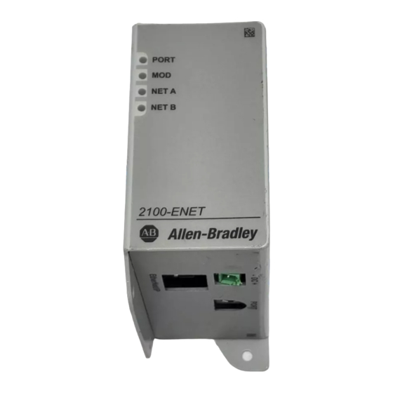
Chapter Troubleshooting This chapter provides information for diagnosing and troubleshooting potential problems with the adapter and network. Topic Page Understanding the Status Indicators PORT Status Indicator MOD Status Indicator NET A Status Indicator NET B Status Indicator Understanding the Status The adapter uses four status indicators to report its operating status. -
Page 58: Port Status Indicator
Chapter 7 Troubleshooting Table 8 - Status Indicators and Descriptions Status Indicator Description Page PORT End Device Connection Status Adapter Status NET A EtherNet/IP network Connection Status NET B EtherNet/IP network Transmit Status PORT Status Indicator This red/green bicolor status indicator indicates the status of the adapter’s connection to the end device. -
Page 59: Net A Status Indicator
Troubleshooting Chapter 7 NET A Status Indicator This red/green bicolor status indicator indicates the status of the network connection. Status Cause Corrective Actions The adapter is not powered, the adapter is • Securely connect the adapter to the end device by using the 2100-ENET adapter not properly connected to the network, the to DeviceNet cable and to the network by using an Ethernet cable. - Page 60 Chapter 7 Troubleshooting Notes: Rockwell Automation Publication 2100-UM006A-EN-P - July 2013...
-
Page 61: Communication
Appendix Specifications Appendix A presents the specifications for the adapter. Topic Page Communication Electrical Mechanical Environmental Regulatory Compliance Communication Attribute 2100-ENET Adapter Work Protocol EtherNet/IP network Data Rates, full-duplex 10 Mbps 100 Mbps Data Rates, half duplex 10 Mbps 100 Mbps Connection limits 30 TCP connections 16 simultaneous CIP connections, including 1 exclusive-owner I/O... -
Page 62: Electrical
Chapter A Specifications Electrical Attribute 2100-ENET Adapter Consumption, end device See the user manual for the end device Consumption, 2100-ENET adapter 92 mA at 24V DC Mechanical Attribute 2100-ENET Adapter Dimensions (HxLxW), approx 19 x 86 x 78.5 mm (0.75 x 3.39 x 3.09 in.) Weight, approx 85 g (3 oz) Environmental... - Page 63 EtherNet/IP, ControlNet, and DeviceNet networks. The protocol is used for implicit messaging (real-time I/O) and explicit messaging (configuration, data collection, and diagnostics). ControlFLASH An Allen-Bradley software tool that lets users electronically update firmware on printed circuit boards. Controller A controller, also called programmable logic controller, is a solid-state control...
- Page 64 Electronic Data Sheet (EDS) Files Simple text files that are used by network configuration tools such as RSNetWorx for EtherNet to describe products so that you can easily commission them on a network. EDS files describe a product device type and revision. EDS files for many Allen-Bradley products can be found at http://www.ab.com/networks/ eds.
- Page 65 Glossary I/O Data I/O data, sometimes called implicit messages or input/output, is time-critical data such as a Logic Command and Reference. The terms input and output are defined from the controller’s point of view. Output is produced by the controller and consumed by the adapter.
- Page 66 Glossary Nonvolatile Storage (NVS) NVS is the permanent memory of a device. Devices such as the adapter and E3 Plus module store parameters and other information in NVS so that they are not lost when the device loses power. NVS is sometimes called EEPROM. Ping A message that is sent by one end device to its peripheral devices.
- Page 67 This protocol ensures that adapters transmit the most recent data because it does not use acknowledgements or retries. Update The process of updating firmware in a device. The adapter can be updated by using various Allen-Bradley software tools. Refer to Update the Adapter on page 24 for more information.
- Page 68 Glossary Notes: Rockwell Automation Publication 2100-UM006A-EN-P - July 2013...
- Page 69 Index duplex communication mode definition 64 adapter selecting 22 applying power 15 commissioning 16 compatible products 10 configuration tools 17 EEPROM, see Nonvolatile Storage (NVS) connecting to the network 15 electronic data sheet (EDS) files definition 63 features 9 definition/website 64 installation 13 environmental specifications 62 IP address 17...
- Page 70 Index ControlLogix controller 26 configuring the adapter for 22 parameters definition 65 accessing 17 limitations when using convention 6 PLC-5, SLC 500 or MicroLogix 1100 con- restoring to factory-default settings 24 troller 39 ping 66 understanding the I/O image 41 using with PLC-5 controller ControlLogix controller 44...
- Page 71 Index technical support 6 tools required 10 Transmission Control Protocol (TCP) 67 troubleshooting 57 update guidelines 24 User Datagram Protocol (UDP) 67 website BOOTP utility 63 EDS files 64 EtherNet/IP network 64 ODVA (Open DeviceNet Vendor’s Association) RSLogix 5, RSLogix 500, and RSLogix 5000 software 66 wiring, see cables zero data...
- Page 72 Index Notes: Rockwell Automation Publication 2100-UM006A-EN-P - July 2013...
- Page 73 Index Notes: Rockwell Automation Publication 2100-UM006A-EN-P - July 2013...
- Page 74 Index Notes: Rockwell Automation Publication 2100-UM006A-EN-P - July 2013...
- Page 76 Rockwell Automation Support Rockwell Automation provides technical information on the Web to assist you in using its products. At http://www.rockwellautomation.com/support, you can find technical manuals, technical and application notes, sample code and links to software service packs, and a MySupport feature that you can customize to make the best use of these tools.
Need help?
Do you have a question about the 2100-ENET Series and is the answer not in the manual?
Questions and answers