Table of Contents
Advertisement
Quick Links
Advertisement
Table of Contents

Related Manuals for Allen-Bradley 20-COMM-M Modbus/TCP Adapter


Summary of Contents for Allen-Bradley 20-COMM-M Modbus/TCP Adapter
- Page 1 20-COMM-M Modbus/TCP Adapter Firmware 1.xxx User Manual...
- Page 2 Rockwell Automation, Inc. EtherNet/IP is a trademark of ODVA and COntrolNet International, Ltd. Ethernet is a trademark of Digital Equipment Corporation, Intel Corporation, and Xerox Corporation. Windows and Microsoft are registered trademarks of Microsoft Corporation. 20-COMM-M Modbus/TCP Adapter User Manual...
- Page 3 Description of Changes Page In the subsection “Direct Access Method,” added a TIP to determine the starting register for a 0-based Modbus/TCP master device, and the registers to read for the example provided. 20-COMM-M Modbus/TCP Adapter User Manual Publication 20COMM-UM014C-EN-P...
- Page 4 Summary of Changes 20-COMM-M Modbus/TCP Adapter User Manual Publication 20COMM-UM014C-EN-P...
-
Page 5: Table Of Contents
Supported Modbus Registers ..........4-15 20-COMM-M Modbus/TCP Adapter User Manual... - Page 6 PowerFlex 700S Drives ........... C-3 Glossary Index 20-COMM-M Modbus/TCP Adapter User Manual Publication 20COMM-UM014C-EN-P...
-
Page 7: Preface
For information such as firmware updates or answers to drive-related questions, go to the Drives Service & Support web site at www.ab.com/ support/abdrives and click on the “Downloads” or “Knowledgebase” link. 20-COMM-M Modbus/TCP Adapter User Manual Publication 20COMM-UM014C-EN-P... -
Page 8: Rockwell Automation Support
File menu and then click the Open command. The firmware release is displayed as FRN X.xxx. The “FRN” signifies Firmware Release Number. The “X” is the major release number. The “xxx” is the minor update number. 20-COMM-M Modbus/TCP Adapter User Manual Publication 20COMM-UM014C-EN-P... -
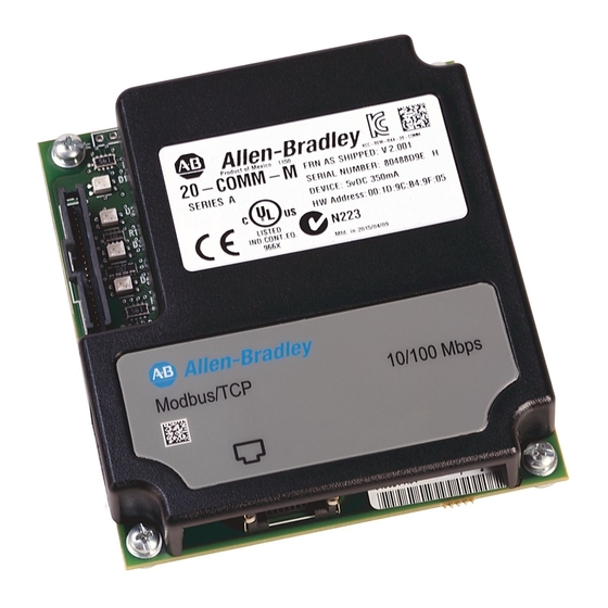
Page 9: Components
100Base-TX Ethernet connections. Web Pages Switch Enables or disables the adapter web pages. Refer to Setting the (SW2) Web Pages Switch on page 2-2. SW1 is unused. 20-COMM-M Modbus/TCP Adapter User Manual Publication 20COMM-UM014C-EN-P... -
Page 10: Features
DPI. At the time of publication, compatible products include: PowerFlex 70/70EC drives PowerFlex 700L drives PowerFlex 700/700VC drives PowerFlex Digital DC drives PowerFlex 700H drives DPI External Comms Kit PowerFlex 700S drives SMC™ Flex 20-COMM-M Modbus/TCP Adapter User Manual Publication 20COMM-UM014C-EN-P... -
Page 11: Required Equipment
ESD control procedures. Static control precautions are required when handling the adapter. If you are unfamiliar with static control procedures, refer to Guarding Against Electrostatic Damage (publication 8000-4.5.2). 20-COMM-M Modbus/TCP Adapter User Manual Publication 20COMM-UM014C-EN-P... - Page 12 Modbus/TCP control network from the enterprise-wide Ethernet network. This can be accomplished by: Making the Modbus/TCP control network a stand-alone network. Placing a firewall between the Modbus/TCP control network and the enterprise-wide Ethernet network. 20-COMM-M Modbus/TCP Adapter User Manual Publication 20COMM-UM014C-EN-P...
-
Page 13: Quick Start
I/O configuration Fault action Set up the master device to communicate with the adapter. Instructions for your network tool Use a network tool to configure the master device on the Modbus/ TCP network. 20-COMM-M Modbus/TCP Adapter User Manual Publication 20COMM-UM014C-EN-P... -
Page 14: Status Indicators
Item Name PORT NET A NET B After installing the adapter and applying power to the drive, refer to Start-Up Status Indications on page 2-6 for possible start-up status indications and their descriptions. 20-COMM-M Modbus/TCP Adapter User Manual Publication 20COMM-UM014C-EN-P... -
Page 15: Preparing For An Installation
ESD control procedures. Static control precautions are required when handling the adapter. If you are unfamiliar with static control procedures, refer to Guarding Against Electrostatic Damage (publication 8000-4.5.2). 20-COMM-M Modbus/TCP Adapter User Manual Publication 20COMM-UM014C-EN-P... -
Page 16: Setting The Web Pages Switch
Setting Web Pages Switch UNUSED WEB PAGES SWITCH SWITCH Enable Web Position Disable Web Position SW2 Setting Description Down (OFF) position Disables the adapter web pages (default setting) Up (ON) position Enables the adapter web pages 20-COMM-M Modbus/TCP Adapter User Manual Publication 20COMM-UM014C-EN-P... -
Page 17: Connecting The Adapter To The Drive
– On a PowerFlex 700, PowerFlex 700H or PowerFlex 700S drive, mount the adapter on the drive using the four captive screws. Important: Tighten all screws to properly ground the adapter. Recommended torque is 0.9 N m (8.0 lb in). 20-COMM-M Modbus/TCP Adapter User Manual Publication 20COMM-UM014C-EN-P... - Page 18 PowerFlex 700H Frames 9 and Larger PowerFlex 700S Frames 9 and Larger Item Description 15.24 cm (6 in.) Internal Interface cable DPI Connector Ethernet cable 2.54 cm (1 in.) Internal Interface cable 20-COMM-M Modbus/TCP Adapter User Manual Publication 20COMM-UM014C-EN-P...
- Page 19 After tightening the screw, verify continuity exists between the head of the screw and drive ground. PowerFlex 700H Frames 9 and Larger PowerFlex 700S Frames 9 and Larger (Adapter mounts behind HIM panel.) 20-COMM-M Modbus/TCP Adapter User Manual Publication 20COMM-UM014C-EN-P...
-
Page 20: Connecting The Adapter To The Network
After power has been applied, the status indicators for the drive and communications adapter can be viewed on the front of the drive (Figure 2.5). Possible start-up status indications are shown in Table 2.A. 20-COMM-M Modbus/TCP Adapter User Manual Publication 20COMM-UM014C-EN-P... - Page 21 NET B Green Normal Operation. The adapter is properly connected but is idle. Flashing Normal Operation. The adapter is properly connected, BOOTP is enabled, and the adapter is transmitting data packets on the network. 20-COMM-M Modbus/TCP Adapter User Manual Publication 20COMM-UM014C-EN-P...
-
Page 22: Commissioning The Adapter
Parameters 04 - [IP Addr Cfg 1] through 07 - [IP Addr Cfg 4]) are recognized only when power is applied to the adapter or it is reset. After you change parameter settings, cycle power or reset the adapter. 20-COMM-M Modbus/TCP Adapter User Manual Publication 20COMM-UM014C-EN-P... -
Page 23: Configuration Tools
BOOTP Server page 3-3 DriveExplorer Software http://www.ab.com/drives/driveexplorer, or (version 2.01 or higher) DriveExplorer online help (installed with the software) DriveExecutive Software http://www.ab.com/drives/drivetools, or (version 3.01 or higher) DriveExecutive online help (installed with the software) 20-COMM-M Modbus/TCP Adapter User Manual Publication 20COMM-UM014C-EN-P... -
Page 24: Using The Powerflex 7-Class Him
Main Menu: Diagnostics Parameter Device Select NOTE: All configuration procedures throughout this chapter use the PowerFlex 7-Class LCD HIM to access parameters in the adapter and show example LCD HIM screens. 20-COMM-M Modbus/TCP Adapter User Manual Publication 20COMM-UM014C-EN-P... -
Page 25: Using Bootp
3. To properly configure devices on your Modbus/TCP network, you must configure settings in the BOOTP software to match the network. Select Tools > Network Settings to display the Network Settings window (Figure 3.2). 20-COMM-M Modbus/TCP Adapter User Manual Publication 20COMM-UM014C-EN-P... - Page 26 Figure 3.3 New Entry Dialog Box 7. Edit the following: Type IP Address A unique IP address for the adapter Host Name Optional Description Optional For definitions of these terms, refer to the Glossary. 20-COMM-M Modbus/TCP Adapter User Manual Publication 20COMM-UM014C-EN-P...
- Page 27 TIP: To enable BOOTP for an adapter that has had BOOTP disabled, first select the adapter in the Relation List, then click Enable BOOTP, and finally reset the adapter or power cycle the drive. 10. To save the Relation List, select File > Save. 20-COMM-M Modbus/TCP Adapter User Manual Publication 20COMM-UM014C-EN-P...
-
Page 28: Setting The Ip Address, Subnet Mask, And Gateway Address
0 <> 255 3. Reset the adapter (see Resetting the Adapter on page 3-12). The NET A status indicator will be steady green or flashing green if the IP address is correctly configured. 20-COMM-M Modbus/TCP Adapter User Manual Publication 20COMM-UM014C-EN-P... - Page 29 20-COMM-M [Gateway Cfg 1] Parameter #: 12 [Gateway Cfg 2] Gateway Cfg 1 [Gateway Cfg 3] [Gateway Cfg 4] 0 <> 255 3. Reset the adapter (see Resetting the Adapter on page 3-12). 20-COMM-M Modbus/TCP Adapter User Manual Publication 20COMM-UM014C-EN-P...
-
Page 30: Setting The Data Rate
Also, verify that the mask parameters (for example, Parameter 276 - [Logic Mask]) in the drive are configured to receive the desired logic from the adapter. Refer to the documentation for your drive for details. 20-COMM-M Modbus/TCP Adapter User Manual Publication 20COMM-UM014C-EN-P... -
Page 31: Setting A Communication Fault Action
(Parameters 26 - [Flt Cfg Logic] through 35 - [Flt Cfg D2 In]). Figure 3.11 Example Fault Action LCD HIM Screens Port 5 Device 20-COMM-M Parameter #: 23 Comm Flt Action Fault Changes to this parameter takes effect immediately. A reset is not required. 20-COMM-M Modbus/TCP Adapter User Manual Publication 20COMM-UM014C-EN-P... -
Page 32: Setting The Message I/O Timer
Figure 3.12 Example Ref Adjust LCD HIM Screen Default = 5 sec Port 5 Device 20-COMM-M Parameter #: 19 Msg I/O Timer 0 <> 180 Changes to this parameter takes effect immediately. A reset is not required. 20-COMM-M Modbus/TCP Adapter User Manual Publication 20COMM-UM014C-EN-P... -
Page 33: Setting Web Access Control
E-mail Cfg Bit 0 is the right-most bit. In Figure 3.13 it is highlighted and equals “1.” Changes to this parameter take effect immediately. A reset is not required. 20-COMM-M Modbus/TCP Adapter User Manual Publication 20COMM-UM014C-EN-P... -
Page 34: Resetting The Adapter
Definition Default x x x 0 0 0 0 1 0 = I/O disabled 7 6 5 4 3 2 1 0 1 = I/O enabled 20-COMM-M Modbus/TCP Adapter User Manual Publication 20COMM-UM014C-EN-P... -
Page 35: Flash Updating The Adapter
This site contains all firmware update files and associated Release Notes that describe firmware update enhancements/ anomalies, how to determine the existing firmware version, and how to flash update using DriveExplorer, DriveExecutive, ControlFLASH or HyperTerminal. 20-COMM-M Modbus/TCP Adapter User Manual Publication 20COMM-UM014C-EN-P... - Page 36 3-14 Configuring the Adapter Notes: 20-COMM-M Modbus/TCP Adapter User Manual Publication 20COMM-UM014C-EN-P...
-
Page 37: Understanding Modbus/Tcp
10000 for others. TIP: When using a Modbus/TCP controller that provides a selection for Internet Protocol (IP), select Ethernet II framing since it is used by the adapter. Do not select IEEE 802.3 LLC/SNAP framing. 20-COMM-M Modbus/TCP Adapter User Manual Publication 20COMM-UM014C-EN-P... - Page 38 DPI Port 1 (HIM in drive cradle) DPI Port 2 (remote-mount HIM or adapter in DPI External Comms Kit) DPI Port 3 (peripheral connected to Port 3 of a two-way or four-way splitter cable) 20-COMM-M Modbus/TCP Adapter User Manual Publication 20COMM-UM014C-EN-P...
-
Page 39: Using The I/O
Parameter 19 - [Msg I/O Timer] to avoid a communication loss. For example, if parameter 19 is set to 5 seconds (default), write a value to register address 10002 every 4.9 seconds or less. 20-COMM-M Modbus/TCP Adapter User Manual Publication 20COMM-UM014C-EN-P... - Page 40 4.E). Table 4.D shows that there are 16 discrete registers to represent the Logic Command word bit by bit. These registers are used only for writing single bits or multiple bits of commands. 20-COMM-M Modbus/TCP Adapter User Manual Publication 20COMM-UM014C-EN-P...
- Page 41 Table 4.D. For other products, refer to their documentation. To set the Reference, you must write the decimal values to register addresses 10003 and 10004 (Table 4.F) using Function Code 16 or 23. 20-COMM-M Modbus/TCP Adapter User Manual Publication 20COMM-UM014C-EN-P...
- Page 42 “1” (Max Speed), the speed Reference scaling is equal to parameter 82 - [Max Speed]: Parameter 82 = Scaling Therefore, 0…32767 = 0…60.0 Hz. If parameter 82 - [Maximum Speed] is changed to 90 Hz, then: 90 Hz = 32767 20-COMM-M Modbus/TCP Adapter User Manual Publication 20COMM-UM014C-EN-P...
- Page 43 Alarm 0 = No Alarm (Par. 211 & 212) 1 = Alarm Fault 0 = No Fault (Par. 243) 1 = Fault At Speed 0 = Not At Reference 1 = At Reference 20-COMM-M Modbus/TCP Adapter User Manual Publication 20COMM-UM014C-EN-P...
- Page 44 Address 10023 Feedback Lo Bit 0…15 of 32-bit Feedback or the whole 16-bit Feedback 10024 Feedback Hi Bit 16…31 of 32-bit Feedback For a 16-bit Feedback, you must read the complete 32-bit value. 20-COMM-M Modbus/TCP Adapter User Manual Publication 20COMM-UM014C-EN-P...
-
Page 45: Accessing Device Parameters
TIP: For a 0-based Modbus/TCP master device, subtract 1 for the starting register address. Therefore, in the example above, read both the starting register address 4 (Lo Word) and register address 6 (Hi Word) to receive drive Parameter 003 - [Output Current] data. 20-COMM-M Modbus/TCP Adapter User Manual Publication 20COMM-UM014C-EN-P... - Page 46 “10000” for the Device Starting Address in the formula above. In this case, set adapter Parameter 38 - [Indirect Par #1] to a value of “10022” for this example to access adapter Parameter 22 - [Reset Module]. 20-COMM-M Modbus/TCP Adapter User Manual Publication 20COMM-UM014C-EN-P...
- Page 47 10066 Hi Word 10067 Indirect Parameter #14 Data Lo Word 10068 Hi Word 10069 Indirect Parameter #15 Data Lo Word 10070 Hi Word 10071 Indirect Parameter #16 Data Lo Word 10072 Hi Word 20-COMM-M Modbus/TCP Adapter User Manual Publication 20COMM-UM014C-EN-P...
-
Page 48: Using Datalinks
Thus, use Datalinks when you need to change a value of a parameter frequently. Reading Datalinks Use the register addresses in Table 4.L to read Datalinks using Function Code 03 or 23. 20-COMM-M Modbus/TCP Adapter User Manual Publication 20COMM-UM014C-EN-P... - Page 49 Hi Word 10017 Datalink D1 In Lo Word 10018 Hi Word 10019 Datalink D2 In Lo Word 10020 Hi Word Any Datalink In can also be read using Function Code 03 or 23. 20-COMM-M Modbus/TCP Adapter User Manual Publication 20COMM-UM014C-EN-P...
- Page 50 Parameter 242 - [Power Up Marker] = 88.4541 hours MSW = 000D = 1101 = 851968 binary LSW = 7F3D = 32573 Engineering Value = 851968 + 32573 = 884541 Parameter 242 Displayed Value = 88.4541 Hrs 20-COMM-M Modbus/TCP Adapter User Manual Publication 20COMM-UM014C-EN-P...
-
Page 51: Supported Modbus Registers
Datalink C1 In Lo Word 4x10014 Datalink C1 In Hi Word 4x10015 Datalink C2 In Lo Word 4x10016 Datalink C2 In Hi Word 4x10017 Datalink D1 In Lo Word 4x10018 Datalink D1 In Hi Word 20-COMM-M Modbus/TCP Adapter User Manual Publication 20COMM-UM014C-EN-P... - Page 52 Indirect Parameter #14 Lo Word 4x10068 Indirect Parameter #14 Hi Word 4x10069 Indirect Parameter #15 Lo Word 4x10070 Indirect Parameter #15 Hi Word 4x10071 Indirect Parameter #16 Lo Word 4x10072 Indirect Parameter #16 Hi Word 20-COMM-M Modbus/TCP Adapter User Manual Publication 20COMM-UM014C-EN-P...
-
Page 53: Chapter 5 Troubleshooting
Figure 5.1. Indicators Figure 5.1 Status Indicators (location on drive may vary) Item Status Indicator Description Page PORT DPI Connection Status Adapter Status NET A Modbus/TCP Connection Status NET B Modbus/TCP Transmit Status 20-COMM-M Modbus/TCP Adapter User Manual Publication 20COMM-UM014C-EN-P... -
Page 54: Port Status Indicator
Verify that the controller can send messages to the adapter. I/O data. Normal behavior if no DPI I/O is enabled. Steady Green The adapter is operational and transferring I/O data. No action required. 20-COMM-M Modbus/TCP Adapter User Manual Publication 20COMM-UM014C-EN-P... -
Page 55: Net A Status Indicator
Check the IP address in the adapter and scanner, and verify that the controller can communicate with the adapter. Ping the adapter. Normal condition if the adapter is idle. Flashing Green The adapter is transmitting on the No action required. network. 20-COMM-M Modbus/TCP Adapter User Manual Publication 20COMM-UM014C-EN-P... -
Page 56: Viewing Adapter Diagnostic Items
The maximum value (since reset) of the DPI Receive error counter. 25 DPI Tx Errors The present value of the DPI Transmit error counter. 26 DPI Tx Error Max The maximum value (since reset) of the DPI Transmit error counter. 20-COMM-M Modbus/TCP Adapter User Manual Publication 20COMM-UM014C-EN-P... - Page 57 Number of receive errors reported by the Ethernet hardware. 50 EN Tx Packets Number of Ethernet packets that the adapter has sent. 51 EN Tx Errors Number of transmit errors reported by the Ethernet hardware. 20-COMM-M Modbus/TCP Adapter User Manual Publication 20COMM-UM014C-EN-P...
-
Page 58: Viewing And Clearing Events
Clear Event Clr Event Queue 5. Press the (Enter) key to confirm your request. If Clr Event Queue was selected, all event queue entries will then display “No Event.” 20-COMM-M Modbus/TCP Adapter User Manual Publication 20COMM-UM014C-EN-P... - Page 59 The adapter uses the same IP address as another device on the network. 40-41 Reserved Not used. Email Failed The adapter encountered an error attempting to send a requested e-mail message. 43-48 Reserved Not used. 20-COMM-M Modbus/TCP Adapter User Manual Publication 20COMM-UM014C-EN-P...
- Page 60 Troubleshooting Notes: 20-COMM-M Modbus/TCP Adapter User Manual Publication 20COMM-UM014C-EN-P...
-
Page 61: Accessing The Adapter's Web Home Page
Bit 0 of Parameter 37 - [Web Features] can be used to protect the configured settings. For more details, see Configure E-mail Notification Web Page on page 6-6. 20-COMM-M Modbus/TCP Adapter User Manual Publication 20COMM-UM014C-EN-P... - Page 62 (at far left) Adapter Title (middle) Shows the adapter type or user-configurable title. Rockwell Automation logo This logo is a hyperlink. Click it to view the Rockwell Automation web (at far right) Home Page. 20-COMM-M Modbus/TCP Adapter User Manual Publication 20COMM-UM014C-EN-P...
- Page 63 The adapter Home Page displays the following information for the adapter and host: Information for Description Adapter Revision IP Address Ethernet Address (MAC) Serial Number Status I/O Connection Status Host “X” Revision Status Commanded Direction Rotation Direction Process Status 20-COMM-M Modbus/TCP Adapter User Manual Publication 20COMM-UM014C-EN-P...
-
Page 64: Process Display Pop-Up Window
The parameter whose value is shown on this line is the feedback value from the drive, and is not selectable. The parameter whose value is shown on this line can be set by using the HIM. For details, see the drive User Manual. 20-COMM-M Modbus/TCP Adapter User Manual Publication 20COMM-UM014C-EN-P... -
Page 65: Tcp/Ip Configuration Web Page
Ethernet Receive Overruns Number of receive buffer overruns reported by the hardware. Ethernet Transmitted Packets Number of packets that the adapter has sent. Ethernet Transmit Errors Number of transmit errors reported by the hardware. 20-COMM-M Modbus/TCP Adapter User Manual Publication 20COMM-UM014C-EN-P... -
Page 66: Configure E-Mail Notification Web Page
If you only want e-mail notification when selected faults/alarms occur: A. Click the respective fault and/or alarm radio buttons. B. Click the “selected faults” link and/or “selected alarms” link. Figure 6.5 shows an example faults configuration page. 20-COMM-M Modbus/TCP Adapter User Manual Publication 20COMM-UM014C-EN-P... - Page 67 C. On the c:\ > command line, type “nslookup [name of e-mail server].” The entry “c:\ > nslookup smtp.company.com” is an example. D. Press ENTER to display the e-mail server IP address (see Figure 6.6). 20-COMM-M Modbus/TCP Adapter User Manual Publication 20COMM-UM014C-EN-P...
- Page 68 TIP: To stop e-mail messages, uncheck all of the “Send an e-mail message when…” boxes. Disabling the adapter web pages by setting the Web Pages Switch (SW2 in Figure 2.1) to the “Disable Web” position will NOT stop the adapter from sending e-mail messages. 20-COMM-M Modbus/TCP Adapter User Manual Publication 20COMM-UM014C-EN-P...
-
Page 69: Dpi Device Information
Firmware revision used by the device Serial Number Serial number of the device Status Operating status of the device (for example, faulted) Figure 6.9 Example of Port 0 (PowerFlex 70 Drive) Diagnostic Items Page 20-COMM-M Modbus/TCP Adapter User Manual Publication 20COMM-UM014C-EN-P... - Page 70 6.11) showing that the alarm queue is not available. Figure 6.11 Example of Port 0 (PowerFlex 70 Drive) Alarm Queue Page Figure 6.12 shows an example event queue page for the Port 5 device (20-COMM-M adapter). 20-COMM-M Modbus/TCP Adapter User Manual Publication 20COMM-UM014C-EN-P...
- Page 71 Viewing the Adapter’s Web Pages 6-11 Figure 6.12 Example of Port 5 (20-COMM-M Adapter) Event Queue Page 20-COMM-M Modbus/TCP Adapter User Manual Publication 20COMM-UM014C-EN-P...
- Page 72 6-12 Viewing the Adapter’s Web Pages Notes: 20-COMM-M Modbus/TCP Adapter User Manual Publication 20COMM-UM014C-EN-P...
- Page 73 Comms Kit Enclosure Cover Enclosure Base (with adapter mounted inside) Internal Interface Cable (connects power supply board in enclosure base to adapter) For more information, refer to the DPI External Communications Kit Installation Instructions (publication 20COMM-IN001). 20-COMM-M Modbus/TCP Adapter User Manual Publication 20COMM-UM014C-EN-P...
- Page 74 Installing the Adapter in a DPI External Comms Kit (20-XCOMM-DC-BASE) Notes: 20-COMM-M Modbus/TCP Adapter User Manual Publication 20COMM-UM014C-EN-P...
-
Page 75: Appendix A Specifications
350 mA at 5 VDC supplied by the host (drive or DPI External Comms Kit) Network None Mechanical Dimensions Height 19 mm (0.75 inches) Length 86 mm (3.39 inches) Width 78.5 mm (3.09 inches) Weight 85 g (3 oz.) 20-COMM-M Modbus/TCP Adapter User Manual Publication 20COMM-UM014C-EN-P... -
Page 76: Environmental
CTick EN61800-3 NOTE: This is a product of category C2 according to IEC 61800-3. In a domestic environment this product may cause radio interference in which case supplementary mitigation measures may be required. 20-COMM-M Modbus/TCP Adapter User Manual Publication 20COMM-UM014C-EN-P... -
Page 77: Appendix B Adapter Parameters
[IP Addr Cfg 1] [IP Addr Cfg 2] [IP Addr Cfg 3] [IP Addr Cfg 4] Important: To set the IP address using these parameters, Parameter 03 - [BOOTP] must be set to “0” (Disabled). 20-COMM-M Modbus/TCP Adapter User Manual Publication 20COMM-UM014C-EN-P... - Page 78 3 = 100 Mbps Full 4 = 100 Mbps Half Type: Read Only 18 [Modbus/TCP Port] Default: Minimum: Sets the TCP port used to transport Modbus/TCP Maximum: 65535 messages. Type: Read/Write Reset Required: Yes 20-COMM-M Modbus/TCP Adapter User Manual Publication 20COMM-UM014C-EN-P...
- Page 79 When commissioning the drive, verify that your system responds correctly to various situations (for example, a disconnected cable). 20-COMM-M Modbus/TCP Adapter User Manual Publication 20COMM-UM014C-EN-P...
- Page 80 Default: 0 = Disabled Values: 0 = Disabled Displays the setting of the adapter Web Pages Switch 1 = Enabled (SW2 in Figure 2.1) when the adapter was last reset. Type: Read Only 20-COMM-M Modbus/TCP Adapter User Manual Publication 20COMM-UM014C-EN-P...
- Page 81 Type: Read/Write peripherals) to read or write values with specific Reset Required: No Modbus Function Codes. For details to use these adapter Indirect Par # parameters, see Indirect Access Method on page 4-10. 20-COMM-M Modbus/TCP Adapter User Manual Publication 20COMM-UM014C-EN-P...
- Page 82 Adapter Parameters Notes: 20-COMM-M Modbus/TCP Adapter User Manual Publication 20COMM-UM014C-EN-P...
-
Page 83: Appendix C Logic Command/Status Words
This Reference Select will not function if a digital input (parameters 361-366) is programmed for “Speed Sel 1, 2 or 3” (option 15, 16 or 17). Note that Reference Select is “Exclusive Ownership” – see drive User Manual for more information. 20-COMM-M Modbus/TCP Adapter User Manual Publication 20COMM-UM014C-EN-P... - Page 84 1011 = DPI 3 Manual 1100 = DPI 4 Manual 1101 = DPI 5 Manual 1110 = DPI 6 Manual 1111 = Jog Ref See “Owners” in drive User Manual for further information. 20-COMM-M Modbus/TCP Adapter User Manual Publication 20COMM-UM014C-EN-P...
-
Page 85: Powerflex 700S Drives
A Not Stop condition (logic bit 0 = 0, logic bit 8 = 0, and logic bit 9 = 0) must first be present before a 1 = Start condition will start the drive. To perform this command, the value must switch from “0” to “1.” 20-COMM-M Modbus/TCP Adapter User Manual Publication 20COMM-UM014C-EN-P... - Page 86 1= At Setpoint Speed Enable 0 = Not Enabled 1 = Enabled See Parameter 304 - [Limit Status] in the PowerFlex 700S drive User Manual for a description of the limit status conditions. 20-COMM-M Modbus/TCP Adapter User Manual Publication 20COMM-UM014C-EN-P...
- Page 87 It also reads data in the device and transmits it to the network. The 20-COMM-M Modbus/TCP adapter connects PowerFlex 7-Class drives to a Modbus/TCP network. Adapters are sometimes also called “cards,” “embedded communication options,” “gateways,” “modules,” and “peripherals.”...
- Page 88 The duplex used by the adapter depends on the type of duplex that other network devices, such as switches, support. 20-COMM-M Modbus/TCP Adapter User Manual Publication 20COMM-UM014C-EN-P...
- Page 89 BOOTP utility. HIM (Human Interface Module) A device that can be used to configure and control a drive. PowerFlex 7-Class HIMs (20-HIM-xxx) can be used to configure PowerFlex 7-Class drives and their connected peripherals. 20-COMM-M Modbus/TCP Adapter User Manual Publication 20COMM-UM014C-EN-P...
- Page 90 You can then set the unique IP address for the adapter by using a BOOTP server or by manually configuring parameters in the adapter. The adapter reads the values of these parameters only at power-up. 20-COMM-M Modbus/TCP Adapter User Manual Publication 20COMM-UM014C-EN-P...
- Page 91 The Allen-Bradley PowerFlex 7-Class family of drives supports DPI and includes the PowerFlex 70, PowerFlex 700, PowerFlex 700H, PowerFlex 700S, PowerFlex 700L, and PowerFlex 7000. These drives can be used for applications ranging from 0.37…3000 kW (0.5…4000 HP). 20-COMM-M Modbus/TCP Adapter User Manual Publication 20COMM-UM014C-EN-P...
- Page 92 Zero data results in the drive receiving zero as values for Logic Command, Reference, and Datalink data. If the drive was running and using the Reference from the adapter, it will stay running but at zero Reference. 20-COMM-M Modbus/TCP Adapter User Manual Publication 20COMM-UM014C-EN-P...
- Page 93 G-2 DPI Internal Interface, 2-3, 2-4 DriveExplorer software Ethernet, 2-6 adapter configuration tool, 3-1 CAN (Controller Area Network), G-1 definition/web site, G-2 free lite version, G-2 classes of IP addresses, G-4 20-COMM-M Modbus/TCP Adapter User Manual Publication 20COMM-UM014C-EN-P...
- Page 94 IP address definition/classes, G-4 full duplex, see duplex communication mode setting with BOOTP, 3-3 setting with parameters, 3-6 gateway, G-3 gateway address Keep-Alive Register, 4-3 setting with BOOTP, 3-3 setting with parameters, 3-6 20-COMM-M Modbus/TCP Adapter User Manual Publication 20COMM-UM014C-EN-P...
- Page 95 Internal Interface cable troubleshooting with, 5-3 NET B status indicator locating, 1-6 troubleshooting with, 5-3 safety precautions, 1-3 network cable, 2-6 specifications network IDs, G-4 adapter, A-1 EtherNet/IP subnet mask, G-6 20-COMM-M Modbus/TCP Adapter User Manual Publication 20COMM-UM014C-EN-P...
- Page 96 6-1 to 6-11 web site BOOTP utility, G-1 DriveExecutive software, G-2 DriveExplorer software, G-2 DriveTools SP software, G-2 EDS files, G-3 manuals, P-1 wiring, see cables zero data configuring the adapter for, 3-9 definition, G-6 20-COMM-M Modbus/TCP Adapter User Manual Publication 20COMM-UM014C-EN-P...
- Page 98 U.S. Allen-Bradley Drives Technical Support - Tel: (1) 262.512.8176, Fax: (1) 262.512.2222, Email: support@drives.ra.rockwell.com, Online: www.ab.com/support/abdrives www.rockwellautomation.com Power, Control and Information Solutions Headquarters Americas: Rockwell Automation, 1201 South Second Street, Milwaukee, WI 53204 USA, Tel: (1) 414.382.2000, Fax: (1) 414.382.4444 Europe/Middle East/Africa: Rockwell Automation, Vorstlaan/Boulevard du Souverain 36, 1170 Brussels, Belgium, Tel: (32) 2 663 0600, Fax: (32) 2 663 0640 Asia Pacific: Rockwell Automation, Level 14, Core F, Cyberport 3, 100 Cyberport Road, Hong Kong, Tel: (852) 2887 4788, Fax: (852) 2508 1846 Publication 20COMM-UM014C-EN-P –...
Need help?
Do you have a question about the 20-COMM-M Modbus/TCP Adapter and is the answer not in the manual?
Questions and answers