Table of Contents
Advertisement
Quick Links
Download this manual
See also:
Instructions for Using
Advertisement
Table of Contents

Related Manuals for Infors HT Labfors 5


Summary of Contents for Infors HT Labfors 5
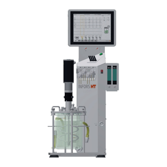
- Page 1 Operating Manual 2019-01-22 Labfors 5 Bench-Top Bioreactor - Version for Microorganisms Dok-ID: 76561 / V.02.00 - Original...
- Page 2 Infors GmbH Infors UK Ltd Infors Dachauer Str. 6 The Courtyard Business Centre Headoffice, Schweiz D-85254 Einsbach Dovers Farm, Lonesome Lane, Rittergasse 27 T +49 (0)8135 8333 Reigate CH-4103 Bottmingen F +49 (0)8135 8320 Surrey, RH2 7QT, UK T +41 (0)61 425 77 00 infors.de@infors-ht.com T +44 (0)1737 22 31 00 F +41 (0)61 425 77 01...
-
Page 3: Table Of Contents
Labfors 5 – Version for Microorganisms Table of Contents General Information ............... 9 About this Manual ............9 Explanation of Special Notices ........9 1.2.1 Warning Notices ..........9 1.2.2 Other Notices..........10 Equipment Identification (Standard Identification Plate) ..................10 Declaration of Conformity .......... - Page 4 Labfors 5 – Version for Microorganisms Table of Contents 3.1.8.1 Connections for Single Walled Vessels ......... 25 3.1.8.2 Connections for Double Walled Vessels ......... 26 3.1.9 Gassing Connection (Sparger) .....27 3.1.10 Sensor Connections (Sensor Cables) ..27 3.1.11 Connections and Valve for Water Flow Regulation of the Exit Gas Cooler ....28...
- Page 5 Labfors 5 – Version for Microorganisms Table of Contents Exit Gas Analysis ............48 4.4.1 Measuring Systems (Gas Sensors) ..... 48 4.4.2 Connecting the Gas Sensors ....... 48 4.4.3 Calibration ............ 50 4.4.4 Replacing the BlueVary Gas Sensor Cartridge ..............50 Multiplexer (Gas Switching Module) ......
- Page 6 Labfors 5 – Version for Microorganisms Table of Contents 5.20 Exit Gas Cooler ............85 5.21 Reagent Bottles ............87 5.22 Antifoam Sensor ............89 5.23 Pump Heads ..............89 5.24 Sterile Filters ..............90 5.25 O-Rings and Gaskets ...........91 5.26 Hoses and Accessories ..........92 5.27 Inoculation Accessories and Tools ......93...
- Page 7 Labfors 5 – Version for Microorganisms Table of Contents 8.1.13 Equipping Port with Septum Collar and Septum for Inoculation ....... 116 8.1.14 Mounting and Preparing the Exit Gas Cooler ..............117 8.1.15 Mounting the Cold Finger ......119 8.1.16 Checking Lubrication of the Mechanical Seal ..............
- Page 8 Labfors 5 – Version for Microorganisms Table of Contents 8.2.15 Checking the Hoses and Hose Connections ..............148 Fermentation/Cultivation ...........149 Preparing the Medium ..........149 Sampling ..............150 Inoculation ..............153 9.3.1 Inoculation with Inoculation Needle ....154 9.3.2 Inoculation with a Syringe ......155 9.3.3 Inoculation Using Dip Tube / Addition Port Adapter ............155...
- Page 9 Labfors 5 – Version for Microorganisms Table of Contents 10.10 Cleaning the Heater Pad ........... 173 10.11 Maintenance Plan ............173 10.12 Lubricating the Mechanical Seal ........ 175 10.13 Decalcifying the Equipment ........175 10.14 Decalcifying Equipment via Vessel Jacket ....177 11 Interferences ...............
- Page 10 Labfors 5 – Version for Microorganisms Table of Contents 13.6.11 Heater Pads for Single Walled Vessels ..204 13.7 Operating Conditions ..........204 13.8 Emissions ..............204 13.9 Utilities ................204 13.10 Auxiliary Supplies ............205 Page 8 of 205 22 January 2019...
-
Page 11: General Information
Labfors 5 – Version for Microorganisms General Information 1 General Information 1.1 About this Manual This manual enables the safe and efficient handling of the equip- ment. All the information and instructions in this operating manual comply with the current standards, legal regulations, the latest technologi- cal and scientific developments and the knowledge gained from the manufacturer’s many years of experience in this field. -
Page 12: Other Notices
Labfors 5 – Version for Microorganisms General Information WARNING The signal word “WARNING” indicates a potentially dangerous situation that may result in severe or even fatal injuries if not avoided. CAUTION The signal word “CAUTION” indicates a potentially dangerous situation that may result in minor injuries if not avoided. -
Page 13: Declaration Of Conformity
Labfors 5 – Version for Microorganisms General Information 1.4 Declaration of Conformity The equipment is in compliance with the essential requirements of the following Directives: Machinery Directive 2006/42/EC EMC Directive 2014/30/EU The Declaration of Conformity according to EC Machinery Directive 2006/42/EC, annex II 1 A is included in the general documentation supplied with the equipment. -
Page 14: Safety And Responsibility
2.1 Intended Use, Incorrect Use and Misuse The bench-top bioreactor Labfors 5 from INFORS HT is de- signed especially for running bio processes with microorgan- isms or animal cells for research and development in a bio- technology laboratory. -
Page 15: Qualified Personnel
Labfors 5 – Version for Microorganisms Safety and Responsibility For use for special applications not covered by conventional, in- tended use, the equipment must be modified and certified accord- ingly by the manufacturer. Any use of the equipment outside of a biotechnology laboratory, i.e. -
Page 16: Operator
Labfors 5 – Version for Microorganisms Safety and Responsibility Qualified personnel On account of their specific education, training and – in many cases – experience, the qualified personnel required for this work are able to recognise risks and respond accordingly to potential hazards. -
Page 17: Unauthorised Persons
Labfors 5 – Version for Microorganisms Safety and Responsibility Technicians in training Persons in this group who are undergoing training or apprentice- ships are only permitted to use the equipment under supervision and in accordance with the instructions of a trained and qualified technician. -
Page 18: Electrical Current
Labfors 5 – Version for Microorganisms Safety and Responsibility The following notices are general in nature. As such, with a few exceptions they are not repeated in the remaining sections. 2.5.1 Electrical Current The equipment runs on electrical power. There is an immediate risk of fatal injury if contact is made with live parts. -
Page 19: Hot Surfaces
Labfors 5 – Version for Microorganisms Safety and Responsibility 2.6.1 Hot Surfaces For processes that are carried out with temperatures over 55 °C, there is a danger of burns on hot surfaces. Since the equipment is intended for applications at high tempera- tures, it is the responsibility of the users to ensure that they have sufficient protection. -
Page 20: Bioactive Substances Or Pathogenic Organisms
Labfors 5 – Version for Microorganisms Safety and Responsibility 2.6.5 Bioactive Substances or Pathogenic Organisms The use or production of bioactive substances, pathogenic organ- isms or genetically modified cultures entails a significant health risk. As such, special measures must be taken to protect the users for such applications. - Page 21 Labfors 5 – Version for Microorganisms Safety and Responsibility The following must be observed if this is the case: The equipment, the component part or accessory must be en- tirely decontaminated before sending to the manufacturer The provider is therefore required to completely and truthfully ...
-
Page 22: Setup And Function
Labfors 5 – Version for Microorganisms Setup and Function 3 Setup and Function 3.1 Basic Unit Holder for operating unit, manometers and Pumps pressure reduction valves Console Main switch Base plate Sensor cables Holder for gassing unit(s) and optional pres-... -
Page 23: Main Switch
Labfors 5 – Version for Microorganisms Setup and Function The whole measuring and control technology of the bioreactor is integrated in the console of the basic unit. One operating unit with touchscreen software can be used to control up to six bioreactors (culture vessels) see also chapter „Operating Unit“. -
Page 24: Identification Plate
Labfors 5 – Version for Microorganisms Setup and Function The autoclavable pump heads are latched onto a mounting plate. The mounting plate is identically as the drive shafts labelled with the pump names. The pump heads together with the mounting plate can easily be plugged onto or pulled off the drive shafts. -
Page 25: Water Connections
Labfors 5 – Version for Microorganisms Setup and Function 3.1.5 Water Connections The two hose nozzles for connection of water inlet and outlet of the basic unit are situated on the rear side at the bottom of the con- sole. They are labelled with corresponding symbols: Left: Water outlet ... -
Page 26: Signal Connections
Labfors 5 – Version for Microorganisms Setup and Function Manometers are installed after each pressure reduction valve for pressure indication. They are labelled accordingly, e.g. Air etc. 3.1.7 Signal Connections The following signal connectors are situated above the mains socket (from top to bottom): 25 pin Dsub Multi I/O: for connecting analogue and digital in- put and output signals (0/4..20 mA) -
Page 27: Connections For Single Walled Vessels
Labfors 5 – Version for Microorganisms Setup and Function 3.1.8.1 Connections for Single Walled Vessels The socket for cable connection of the electrical heater pad is la- belled and the water connectors for the cold finger are labelled with symbols. -
Page 28: Connections For Double Walled Vessels
Labfors 5 – Version for Microorganisms Setup and Function 3.1.8.2 Connections for Double Walled Vessels The water connectors for the vessel jacket are labelled with corre- sponding symbols. Water overflow vessel jacket Water outlet vessel jacket Water inlet vessel jacket... -
Page 29: Gassing Connection (Sparger)
Labfors 5 – Version for Microorganisms Setup and Function 3.1.9 Gassing Connection (Sparger) The hose nozzle for connection of the gassing hose (sparger) is lo- cated below the holder for gassing unit(s) on the right side of the basic unit. -
Page 30: Connections And Valve For Water Flow Regulation Of The Exit Gas Cooler
Labfors 5 – Version for Microorganisms Setup and Function 3.1.11 Connections and Valve for Water Flow Regulation of the Exit Gas Cooler The water connections for the (optional!) exit gas cooler and the valve for the water flow regulation are located on the left front side of the basic unit. -
Page 31: Operating Panel
Labfors 5 – Version for Microorganisms Setup and Function 3.2 Operating Panel The operating panel has a 12" colour-touch screen with protection IP66. Up to six bioreactors (= culture vessels) can be individually or in parallel controlled by one operating panel. -
Page 32: Operating Panel Connections
Labfors 5 – Version for Microorganisms Setup and Function INFORMATION The ON/OFF key is locked when a bioreactor (fermentation) is running. A dialogue box with the appropriate message appears when pressing the ON/OFF key by mistake during fermentation. When pressing the ON/OFF key when the bioreactor (fermenta-... -
Page 33: Culture Vessels
Labfors 5 – Version for Microorganisms Setup and Function 3.3 Culture Vessels Culture vessels consist of the glass vessel, the top plate with standard mounting parts and handholds and the vessel holder with handholds. The vessels are either made of double or single walled borosilicate glass, depending on the temperature control system used. -
Page 34: Single Walled Culture Vessels
Labfors 5 – Version for Microorganisms Setup and Function 3.3.2 Single walled Culture Vessels Handhold top plate Vessel holder Handhold vessel holder Top plate Glass vessel The picture above shows a single walled culture vessel with a total volume of 3.6 L and DN (diameter nominal = inner diameter) of 115 mm. -
Page 35: Top Plate
Labfors 5 – Version for Microorganisms Setup and Function 3.3.3 Top Plate Four knurled screws are used to fixate the top plate to the glass vessel and the vessel holder. Drive hub and motor coupling are lo- cated in the middle of the vessel top plate. -
Page 36: Top Plate Dn 115
Labfors 5 – Version for Microorganisms Setup and Function 3.3.5 Top Plate DN 115 Ground connector antifoam sensor Ø 12 mm / Pg13.5: Dip tube for sampling Ø 12 mm Pg13.5: Exit gas cooler Ø 19 mm: Spare Ø 12 mm / Pg13.5: Sparger 10 Ø... -
Page 37: Top Plate Dn 150
Labfors 5 – Version for Microorganisms Setup and Function 3.3.6 Top Plate DN 150 Ground connector antifoam sensor Ø 12 mm / Pg13.5: Dip tube for sampling Ø 19 mm: Spare Ø 19 mm: Inoculation needle Ø 10 mm: Temperature sensor (Pt100) 10 Ø... -
Page 38: Top Plate Dn 200
Labfors 5 – Version for Microorganisms Setup and Function 3.3.7 Top Plate DN 200 Ø 19 mm: Spare Ø 19 mm: Spare or cold finger Ø 10 mm: Temperature sensor (Pt100) Ø 19 mm: Spare Ø 10 mm: Antifoam sensor 10 Ø... -
Page 39: Water Temperature Control
Labfors 5 – Version for Microorganisms Setup and Function flow for either the circuit in the double walled vessel or in the cold finger is regulated via solenoid valve. 3.4.1 Water Temperature Control The water temperature control takes place in the vessel jacket, which is connected to the basic unit. -
Page 40: Stirrer
Labfors 5 – Version for Microorganisms Setup and Function 3.5 Stirrer The stirrer shaft is rotated counter clockwise (top view) by a top drive. Drive hub Stirrer shaft Mechanical seal The stirrer shaft is screwed on the drive hub in the vessel top plate and is sealed by a single mechanical seal. -
Page 41: Gassing System
Labfors 5 – Version for Microorganisms Setup and Function A brushless DC motor with mechanical coupling is used as a standard. To couple the motor, it is simply plugged onto the drive hub on the vessel top plate. Two Rushton impellers with six blades are provided as a standard for bacterial cultures. -
Page 42: Gassing Strategy
Labfors 5 – Version for Microorganisms Setup and Function 3.6.1 Gassing Strategy The following variants are available: Basic Manual flow control via rotameter Gasmix via solenoid valves Standard Gas flow control via one electronic mass flow controller ... -
Page 43: Ph Control
Labfors 5 – Version for Microorganisms Setup and Function However, using this method may lead to blocking the exit gas filter due to humidity in the exit gas. For this reason, the use of an exit gas cooler is strongly recommended. -
Page 44: Calibration
Manufacturer: HAMILTON HAMILTON pH sensors are preconfigured before dispatch by the equipment manufacturer INFORS HT. Replacement sensors of this type must be reconfigured before use! Details on technical data, use and maintenance of the pH sensors can be found in the separate documentation of the sensor manu- facturer. -
Page 45: Measuring System
HAMILTON pO sensors are preconfigured before dispatch by the equipment manufacturer INFORS HT. Replacement sensors of this type must be reconfigured before use! Details on technical data, use and maintenance of the pO2 sensors can be found in the separate documentation of the sensor manu- facturer. -
Page 46: Mounting Of The Sensor
Labfors 5 – Version for Microorganisms Setup and Function the oxygen measurement is always calibrated to a relative refer- ence point. For this purpose, the calibration is set to 100 % relative oxygen saturation, usually with air at max. stirring speed and maxi- mum gas flow rate. -
Page 47: Options
Labfors 5 – Version for Microorganisms Options 4 Options The following options are available in addition to the equipment included in the scope of supply for the basic unit. 4.1 Pump(s) Additionally to the four peristaltic pumps, which are integrated on the basic unit by default, two analogue pumps are available. - Page 48 Labfors 5 – Version for Microorganisms Options The servomotor is operated by a separate AC servo amplifier. This is connected to the basic unit via two cables (not visible in the pic- ture to the left). The green power cable and the orange signal cable are connected on the rear side of the amplifier box.
-
Page 49: Level Measurement
Labfors 5 – Version for Microorganisms Options 4.3 Level Measurement Detects liquid in the culture vessel, i.e. measures the level by means of the level sensor. When the level sensor comes in contact with liquid, a signal is generated which is displayed as 100 % in the touch screen software. -
Page 50: Exit Gas Analysis
4.4.1 Measuring Systems (Gas Sensors) The following measuring systems are available for exit gas analy- sis: INFORS HT Gas Analyser: gas analysis equipment (combined and O sensor) from the equipment manufacturer. Gas sensors from the manufacturer BlueSens: combined CO ... - Page 51 Labfors 5 – Version for Microorganisms Options INFORS HT Gas Analyser Connection of the gas analysis equipment from the equipment manufacturer is described in details in its separate documentation. Gas sensors from manufacturer BlueSens The gas sensor must be connected to the sensor cable and the bioreactor’s exit gas must be led into the sensor via hose line.
-
Page 52: Calibration
Labfors 5 – Version for Microorganisms Options 4.4.3 Calibration INFORS HT Gas Analyser The display of measured values on the bioreactor should be cali- brated after the annual maintenance of the gas analyser has been carried out For details about maintenance of the gas analyser refer to its sepa- rate documentation. -
Page 53: Turbidity Measurement
Labfors 5 – Version for Microorganisms Options 4.6 Turbidity Measurement The Optek ASD12-N measurement sensor can be used to deter- mine the turbidity of the culture. Turbidity measurement can be used to draw conclusions regarding the biomass concentration in the culture. -
Page 54: Calibrating The Zero Point
Labfors 5 – Version for Microorganisms Options The sensors possess a measurement segment that is optimised in terms of flow and sterility. The seal-free design of the sapphire win- dow means that there are no gaps or joints. This guarantees com- plete sterility. -
Page 55: Cleaning And Storing The Sensor
Labfors 5 – Version for Microorganisms Options If the mounting depth of the sensor is adjustable (mounting with electrode holder), make sure the mounting depth is set correctly prior to autoclaving, as later adjustment represents a contamination risk. Mount the sensor in such a way that it cannot come in contact ... -
Page 56: Specifications
4.7 Permissive Measurement The sensor with the corresponding transmitters must be purchased directly from the manufacturer ABER. INFORS HT offers a connec- tion to the transmitter on the basic unit. Calibration is performed according to the manufacturer’s guidelines directly on the transmitter. -
Page 57: Redox Measurement
Labfors 5 – Version for Microorganisms Options All information about the ABER Futura system is available in the separate documentation provided by the manufacturer. 4.8 Redox Measurement Measures the reduction/oxidation potential (redox) in the medium. 4.8.1 Measuring Systems (Sensors) Two systems are available for redox measurement:... -
Page 58: Mounting The Sensor
Labfors 5 – Version for Microorganisms Options METTLER system: 1-point calibration in the calibration menu of the redox parameter in the touch screen software from the administrator user level. HAMILTON system: Calibration using a Hamilton Arc Handheld or a Hamilton Arc USB cable, both of which are available separately from the sensor manufacturer. -
Page 59: Pressure Control
Labfors 5 – Version for Microorganisms Options For details about technical data, use and maintenance of the pCO2 sensor and transmitter, refer to the separate documentation from the manufacturer METTLER TOLEDO. Mounting of the sensor pCO2 sensors are mounted into a 12 mm / Pg13.5 port in the ves- sel top plate by the means of an electrode holder. - Page 60 Labfors 5 – Version for Microorganisms Options If pressure control is switched off (parameter Pressure OFF), the valve automatically opens to prevent build-up of pressure in the vessel. For details about the touch screen software refer to the separate operating manual.
-
Page 61: Labcip, Cip/Sip Unit
Labfors 5 – Version for Microorganisms Options Ensure the sensor is equipped with an intact O-ring, fit one if necessary. Carefully screw the pressure sensor into the threaded adapter. Screw the steel cap onto the female sensor connector. After autoclaving The exit gas filter (on the exit gas cooler) must be connected to the pre-installed pressure hose of the solenoid valve. - Page 62 Labfors 5 – Version for Microorganisms Options All information regarding safety, setup and function, operation, maintenance and technical data of the LabCIP is available in the separate operating manual from the equipment manufacturer. Page 60 of 205 22 January 2019...
-
Page 63: Accessories
Labfors 5 – Version for Microorganisms Accessories 5 Accessories The kind and number of accessories included by default in every standard package are listed the following table. It is divided in col- umns according the diameter nominal (= inside diameter in mm) of the vessels and their different sizes (TV = total volume in L). -
Page 64: Base Tray
Labfors 5 – Version for Microorganisms Accessories 5.1 Base Tray Culture vessels are delivered with a base tray made of stainless steel. Dimensions: 373 mm × 373 mm for vessels with DN 115 / 150 423 mm × 423 mm for vessels with DN NW 200 ... - Page 65 Labfors 5 – Version for Microorganisms Accessories The reagent bottle and pump holder can be fitted to the vessel holder. The mounting plate with the pump heads can be fitted to the reagent bottle and pump holder. The holder for 500 mL reagent bottles can be modified using the centering rings, which can be obtained as an optional modification set.
-
Page 66: Sampling System Super Safe Sampler
Labfors 5 – Version for Microorganisms Accessories 5.3 Sampling System Super Safe Sampler Basically different systems and also individual components are available for sampling. This operating manual describes the opera- tion and handling of the aseptic sampling system Super Safe Sam- pler combined with a dip tube. - Page 67 Labfors 5 – Version for Microorganisms Accessories Principle of function The sample valve on the side arm of the T-piece opens by putting the Luer connector of the syringe into the valve and closes by re- moving the syringe. No further handling is necessary.
-
Page 68: Sparger
Labfors 5 – Version for Microorganisms Accessories sample has to be processed under sterile conditions. For sampling, the same non-sterile syringe can be used repeatedly, without fear of contamination of the culture vessel. Aseptic Sampling For each sample, use a new, sterile syringe with Luer Lock fitting, in order to ensure the sterility of the sample. - Page 69 Labfors 5 – Version for Microorganisms Accessories Sparger, L-shaped Inside-Ø 4.0 mm Outside-Ø hose connection 6.0 mm Ring sparger Inside Ø 4.0 mm Outside-Ø hose connection 6.0 mm Page 67 of 205 22 January 2019...
-
Page 70: Impellers
Labfors 5 – Version for Microorganisms Accessories 5.5 Impellers For details about impellers, refer to chapter “Setup and Function”, “Stirrer”. 5.6 Pocket for Temperature Sensor (Pt100) The pocket is a pipe with a sealed bottom end, and is used to in- sert the temperature sensor. -
Page 71: Baffles
Labfors 5 – Version for Microorganisms Accessories 5.7 Baffles Culture vessels are equipped with three baffles by default. Baffle, 3 pieces Must be fitted with O-ring before mounting. A hexalobular screw is used for mounting in the vessel top plate. -
Page 72: Lock Nut
Labfors 5 – Version for Microorganisms Accessories 5.8 Lock Nut If no baffles are used, lock nuts must be fitted into the vessel top plate instead. They are disposable in a set of 3 pieces. Must be fitted with an O-ring before mounting. -
Page 73: Blanking Plugs
Labfors 5 – Version for Microorganisms Accessories 5.9 Blanking Plugs Blanking plugs are used to seal open ports. There are different blanking plugs for the different types of port. Blanking plug, Ø 10 mm Fitted with fixed O-ring. Two slotted screws are used for fixing in 10 mm port Blanking plug, Ø... -
Page 74: Addition Port Adapters
Labfors 5 – Version for Microorganisms Accessories Blanking plug Ø 19 mm Fitted with fixed O-ring. A threaded adapter is used for mounting in 19 mm port. 5.10 Addition Port Adapters Addition port adapters are used for liquid addition into the culture vessel. -
Page 75: Inoculation Needles
Labfors 5 – Version for Microorganisms Accessories Addition port adapter Ø 12 mm Inside-Ø 3.0 mm Outside-Ø hose connection 5.0 mm Muts be fitted with O-ring. Thread is used for mounting in 12 mm / Pg13.5 port. Addition port adapter Ø 12 mm Inside-Ø... - Page 76 Labfors 5 – Version for Microorganisms Accessories pierced with the inoculation needle, which is screwed into the sep- tum collar. The septum may be wetted e.g. with an alcohol solution that is lit up before the piercing. Inoculation needles are purchased including septum collar. They have an oblique tip to facilitate the piercing.
- Page 77 Labfors 5 – Version for Microorganisms Accessories Inoculation needle, Ø 19 mm Inside-Ø 2.5 mm Outside-Ø hose connection 4.5 mm Fitted with fixed O-ring. Thread is used for mounting in septum collar in 19 mm port. Inoculation needle, 19 mm Inside-Ø...
-
Page 78: Septum Collars
Labfors 5 – Version for Microorganisms Accessories Inoculation needle, double, Ø 19 mm Inside-Ø 2.0 mm Outside-Ø hose connection 4.0 mm Fitted with fixed O-ring. Thread is used for mouting in septum collar in 19 mm port. 5.12 Septum Collars... -
Page 79: Dip Tubes
Labfors 5 – Version for Microorganisms Accessories Septum collar, Ø 19 mm With inside thread. Septum must be inserted in port before mounting in 19 mm port. Threaded adapter is used for mounting. Multi-inlet septum collar, system Roussel, Ø 19 mm With inside thread, for inoculation with syringe. - Page 80 Labfors 5 – Version for Microorganisms Accessories Dip tube, straight, Ø 6 mm Inside-Ø 3.0 mm Hose connection outside-Ø 4.2 mm / 5.0 mm The dip tube does not reach as far as the bottom of the vessel. The illustration on the left shows only the upper section of the dip tubes.
-
Page 81: Clamping Adapters
Labfors 5 – Version for Microorganisms Accessories Dip tube, curved with frit, Ø 6 mm Inside-Ø 2.0 mm Hose connection outside-Ø 4.0 mm Pore size of frit 40 µm The dip tube does reach to the vessel bottom. 5.14 Clamping Adapters Clamping adapters are used for mounting the sparger, the various dip tubes and the antifoam/level sensors. - Page 82 Labfors 5 – Version for Microorganisms Accessories Clamping adapter Ø 6 mm / 12 mm Must be fitted with O-ring before mounting. Thread is used for mounting in 12 mm / Pg13.5 Port. After loosening the slotted screw (A) the component part with Ø...
-
Page 83: Electrode Holder
Labfors 5 – Version for Microorganisms Accessories 5.15 Electrode Holder Electrode holders are used for mounting sensors (pH, pO , etc.) in 12 mm/Pg 13.5 ports. They can also be used to adjust the mount- ing depth of the sensor. -
Page 84: Heater Pad
Labfors 5 – Version for Microorganisms Accessories 5.18 Heater Pad The electrical heater pad is needed for heating up single walled vessels. It is fitted around the vessel and held together with the tensioning springs. Power cable Hook Tensioning spring... -
Page 85: Cold Finger
Labfors 5 – Version for Microorganisms Accessories 5.19 Cold Finger A cold finger is provided for single walled vessels for cooling pur- poses. Connection water inlet basic unit Connection water outlet basic unit The cold finger is already equipped with pressure hoses for water inlet (upper connector) and water outlet (lower connector). - Page 86 Labfors 5 – Version for Microorganisms Accessories Cold finger, Ø 19 mm Fitted with fixed O-ring. Threaded adapter is used for mounting in 19 mm port. Cold finger, Ø 12 mm Adjustable mounting depth, Must be fitted with O-ring before mounting.
-
Page 87: Exit Gas Cooler
Labfors 5 – Version for Microorganisms Accessories 5.20 Exit Gas Cooler The exit gas cooler is fully equipped ex-factory. Exit gas cooler Rapid coupling Adjustable hose clamp Plug-in nozzle Exit gas filter The exit gas cooler is supplied with cooling liquid from the basic unit. - Page 88 Labfors 5 – Version for Microorganisms Accessories Exit gas cooler Ø 12 mm Must be equipped with O-ring Its thread is used for mounting in 12 mm / Pg13.5 Port Exit gas cooler Ø 19 mm With fixed O-ring. A threaded adapter is needed for mounting in 19 mm port.
-
Page 89: Reagent Bottles
Labfors 5 – Version for Microorganisms Accessories 5.21 Reagent Bottles For addition of corrective reagent and feed solution (substrate) into the culture vessel, different sizes and models of reagent bottles made of borosilicate glass are available. Size Ø Hose Number of hose... - Page 90 Labfors 5 – Version for Microorganisms Accessories The individual parts of the reagent bottle are: Threaded cap, PBT Plate with two hose nozzles, PVDF Flat gasket, silicone Laboratory bottle, Borosilicate The picture to the left shows the reagent bottle type with 3 + 1 hose connectors.
-
Page 91: Antifoam Sensor
Labfors 5 – Version for Microorganisms Accessories 5.22 Antifoam Sensor If ordered, the antifoam model fitting into Ø 10 mm ports is sup- plied by default. A clamping adaptor with fixed O-ring is used for mounting. Sensor head with port for banana connector (A) -
Page 92: Sterile Filters
Labfors 5 – Version for Microorganisms Accessories 5.24 Sterile Filters Sterile filters are used to protect against contamination in both the gassing line and the exit gas line. In addition to this, all reagent bottles used for pressure equalisation must be fitted with an open, short section of hose with a filter. -
Page 93: O-Rings And Gaskets
Labfors 5 – Version for Microorganisms Accessories Ø 25 mm, not marked Application Reagent bottles (pressure equali- sation) Retention rate 0.45 µm Diaphragm PTFE Ø 50 mm, Type ACro50 TF, no label Usage Inlet air / Exit gas Retention rate 0.2 µm... -
Page 94: Hoses And Accessories
Labfors 5 – Version for Microorganisms Accessories 5.26 Hoses and Accessories Hose type Ø mm Application Pressure hose, fibre- 10 x 17 Water outlet glass-woven Pressure hose, fibre- 8 x 14,5 Water inlet glass-woven Exit gas filter attach- ... -
Page 95: Inoculation Accessories And Tools
Labfors 5 – Version for Microorganisms Accessories Rapid coupling plug water inlet and outlet hoses of nipple, DN12.7 hose vessel jacket (double walled nozzle 1/2" A culture vessels) Rapid coupling plug water overflow hose of vessel nipple DN12.7 hose jacket (double walled culture nozzle 1/2"... -
Page 96: Transport And Storage
Labfors 5 – Version for Microorganisms Transport and Storage 6 Transport and Storage The following specifications are based on transport and storage of an unpacked equipment at the provider’s site. 6.1 Transport WARNING Improper transport, the use of incorrect auxiliary equipment and careless handling of the equipment may lead to injuries and se- vere property damage. -
Page 97: Storage
Labfors 5 – Version for Microorganisms Transport and Storage 6.2 Storage Before each time they are put into storage, decontaminate, thoroughly clean and dry the culture vessel and all accesso- ries Store the equipment and its components clean, dry and pro- ... -
Page 98: Installation And Initial Operation
Labfors 5 – Version for Microorganisms Installation and Initial Operation 7 Installation and Initial Operation Installation and initial operation of the equipment may only be car- ried out by qualified personnel from the manufacturer or personnel authorised by the manufacturer. -
Page 99: Minimum Distances
Labfors 5 – Version for Microorganisms Installation and Initial Operation 7.2 Minimum Distances To operate and maintain the unit it must be installed with a mini- mum spacing of 150 mm from walls, ceilings or other equipment. 7.3 Power Supply... -
Page 100: Gas Supply
Labfors 5 – Version for Microorganisms Installation and Initial Operation Hoses Only use pressure-resistant and intact hoses. Only use appropriate hoses, use adaptors as necessary. Secure hoses with the appropriate clamps. 7.5 Gas Supply The in-house gas supply to the equipment must meet the following requirements: Constant gas supply at a pressure of 2 ±... -
Page 101: Exit Gas
Labfors 5 – Version for Microorganisms Installation and Initial Operation 7.6 Exit Gas On site, it must be ensured that: the exit gas is safely led away by means of a suitable, gas- tight hose. the working environment and/or the laboratory/laboratory-like ... - Page 102 Labfors 5 – Version for Microorganisms Installation and Initial Operation ATTENTION If the vessel top plate presses against long built-in components they may be distorted due to the weight of the top plate. Always position the vessel top plate so that it does not lie on top of components.
- Page 103 Labfors 5 – Version for Microorganisms Installation and Initial Operation Connect the water inlet and water outlet of the cold finger to the basic unit; follow the symbols on the basic unit: Connect the lower pressure hose of the cold finger ...
-
Page 104: Filling The Water Circuit
Labfors 5 – Version for Microorganisms Installation and Initial Operation CAUTION Risk of burns and loss of property due to elevated temperature! The temperature control circuit will overheat without an inserted temperature sensor and/or without liquid in the vessel. This can lead to burns and loss of property. -
Page 105: Stirring
Labfors 5 – Version for Microorganisms Installation and Initial Operation INFORMATION The exit gas cooler only works with activated temperature con- trol (Parameter Temperature ON). Use your hands to check whether the exit gas cooler is begin- ning to cool down. Open the control valve for water flow on the basic unit, if necessary. -
Page 106: Gassing
Labfors 5 – Version for Microorganisms Installation and Initial Operation The temperature of the liquid (water) in the vessel jacket starts increasing. Wait until the temperature has adjusted to the setpoint. For the rest of the procedure, allow the bioreactor to run with the temperature switched on and the stirrer running. - Page 107 Labfors 5 – Version for Microorganisms Installation and Initial Operation CAUTION Risk of minor burns if the motor is touched during operation or its cooling phase! When the motor has cooled down: Uncouple the motor from the vessel and place it on a clean and dry work surface.
-
Page 108: Before Fermentation/Cultivation
Labfors 5 – Version for Microorganisms Before Fermentation/Cultivation 8 Before Fermentation/Cultivation The following chapters describe all the preparatory work before starting the fermentation/cultivation process. This essentially com- prises: Preparing and autoclaving the culture vessel: Checking the gaskets (O-rings) on component parts and ... -
Page 109: Mounting The Impellers
Labfors 5 – Version for Microorganisms Before Fermentation/Cultivation Procedure Check the vessel seal (O-ring) for damage and on correct seat: it must rest firmly on the slightly prominent vessel rim within the metal ring. Place it correctly as necessary. Ensure that each mounting part is equipped with an intact O- ring: check that O-rings are correctly positioned and undam- aged. -
Page 110: Mounting Dip Tubes And Spargers
Labfors 5 – Version for Microorganisms Before Fermentation/Cultivation 8.1.3 Mounting Dip Tubes and Spargers Straight spargers and dip tubes can be mounted to the outside of the vessel top plate. Curved spargers and dip tubes can only be mounted to the inside of the vessel top plate. -
Page 111: Mounting The Baffles
Labfors 5 – Version for Microorganisms Before Fermentation/Cultivation Insert the sparger/dip tube into the clamping adapter from be- low. Set the desired mounting depth. Tighten the slotted screw. 8.1.4 Mounting the Baffles To mount the baffles, proceed as follows: Procedure Fit an O-ring to the baffles. -
Page 112: Moistening/Filling The Culture Vessel
Labfors 5 – Version for Microorganisms Before Fermentation/Cultivation Ensure that the baffles are aligned correctly, so that they fit into the glass vessel (round bottom!). 8.1.5 Moistening/Filling the Culture Vessel If the medium in the culture vessel is to be autoclaved, this can take place before the top plate is put in position and the additional component parts are mounted. -
Page 113: Fitting The Vessel Top Plate
Labfors 5 – Version for Microorganisms Before Fermentation/Cultivation 8.1.6 Fitting the Vessel Top Plate Proceed as follows to fit and fix the vessel top plate: Procedure Place the top plate carefully and with the correct alignment into position. Page 111 of 205... -
Page 114: Mounting A Threaded Adapter
Labfors 5 – Version for Microorganisms Before Fermentation/Cultivation Tighten the knurled screws on the top plate by hand (no tool!) crossways. ATTENTION If the screws are tightened too much, components may be dam- aged, which can result in failure of the equipment. The screws may not be tightened with a tool under any circumstances. -
Page 115: Mounting The Blanking Plugs
Labfors 5 – Version for Microorganisms Before Fermentation/Cultivation 8.1.8 Mounting the Blanking Plugs For mounting the different blanking plugs, proceed as follows: Ø 10 mm Ports Procedure Insert the blanking plug with fixed O-ring into the port. Fix it with both slotted screws. -
Page 116: Mounting Addition Port Adapters
Labfors 5 – Version for Microorganisms Before Fermentation/Cultivation Ø 19 mm ports Procedure Screw the blanking plug with fixed O-ring into the threaded adapter. Tighten it by hand. 8.1.9 Mounting Addition Port Adapters Proceed as follows for mounting: Addition port adapter, quadruple, for Ø 19 mm port Procedure Insert the addition port adapter with fixed O-ring into the port. -
Page 117: Mounting The Pocket For Temperature Sensor (Pt100)
Labfors 5 – Version for Microorganisms Before Fermentation/Cultivation INFORMATION The mounting procedure of further models of addition port adapters (refer to main chapter “Accessories” for details) is the same as for blanking plugs into their corresponding ports. That is why their mounting is not repeatedly described here. -
Page 118: Preparing The Dip Tube/Addition Port Adapter For Inoculation
Labfors 5 – Version for Microorganisms Before Fermentation/Cultivation Procedure Remove protective caps from the inoculation needle. Keep the septum collar ready for use. Connect the inoculation needle via silicone hose with an ap- propriate container for the inoculum. Put the inoculation needle in a sterile cover or wrap it up in some aluminium foil. -
Page 119: Mounting And Preparing The Exit Gas Cooler
Labfors 5 – Version for Microorganisms Before Fermentation/Cultivation Proceed as follows: Procedure Ensure that the port is not equipped with an O-ring, otherwise remove it. Insert the septum into the port. Screw the septum collar into the port by hand. - Page 120 Labfors 5 – Version for Microorganisms Before Fermentation/Cultivation Align the exit gas cooler to ensure that handling of other mounting parts is impaired as little as possible. Check to ensure that the exit gas filter is fitted securely. Cap the exit gas filter loosely with a little aluminium foil.
-
Page 121: Mounting The Cold Finger
Labfors 5 – Version for Microorganisms Before Fermentation/Cultivation 8.1.15 Mounting the Cold Finger If applicable, i.e. temperature control system with electrical heater pad and cold finger is present (system for single walled culture vessels), the cold finger must be mounted in its appropriate port in the vessel top plate. -
Page 122: Calibrating The Ph Sensor
Labfors 5 – Version for Microorganisms Before Fermentation/Cultivation Mount the sensors in such a way that they cannot come in contact with other components or the glass vessel. If the mounting depth of is adjustable (mounting with electrode ... -
Page 123: Mouting A Sensor Into A 12 Mm Port
Labfors 5 – Version for Microorganisms Before Fermentation/Cultivation Procedure Connect the sensor cable. (For more details, see the chapter “Connecting the pH Sensor”). Switch on the equipment using the main switch. The operating panel is switched on automatically and the sys- tem is started. - Page 124 Labfors 5 – Version for Microorganisms Before Fermentation/Cultivation Procedure On the electrode holder, lightly loosen the grub screw in the support guide with the key. Pull the support guide from the guide bar. Insert the sensor into the support guide and tighten it.
- Page 125 Labfors 5 – Version for Microorganisms Before Fermentation/Cultivation Insert the sensor into the hollow screw with the thread pointing in the downward direction. Fit the fork of the guide bar into the groove of the hollow screw. Push the hollow screw and the guide bar together upwards and insert the guide bar into the hole of the support guide.
-
Page 126: Mounting The Antifoam Sensor
Labfors 5 – Version for Microorganisms Before Fermentation/Cultivation Screw the sensor on the hollow screw into the port and tighten 10. Tighten the grub screw in the support guide with the key. 8.1.17.4 Mounting the Antifoam Sensor Note the following points for mounting: The antifoam sensor is equipped with transparent insulation ... - Page 127 Labfors 5 – Version for Microorganisms Before Fermentation/Cultivation Procedure Remove the protective cap from the sensor. Ensure the clamping adapter is equipped with an O-ring, fit one, if necessary. Insert the sensor into the port. Fix the clamping adapter with the two slotted screws.
- Page 128 Labfors 5 – Version for Microorganisms Before Fermentation/Cultivation Procedure Remove the protective cap from the sensor. Depending on type of clamping adapter: Ensure the clamping adapter or port is equipped with an O- ring, fit/place one, if necessary. If 19 mm port: mount a threaded adapter.
-
Page 129: Preparing The Super Safe Sampler
Labfors 5 – Version for Microorganisms Before Fermentation/Cultivation 8.1.18 Preparing the Super Safe Sampler INFORMATION The following figures are for general purposes of comprehen- sion. In order to prepare the Super Safe Sampler sampling system for autoclaving, proceed as follows: Procedure Attach the hose of the valve group on the dip tube. -
Page 130: Mounting The Sparger Hose And The Inlet Air Filter
Labfors 5 – Version for Microorganisms Before Fermentation/Cultivation Turn the sterile filter carefully by hand in a clockwise direction. This ensures that the non-return valve/sterile filter screw con- nection is tight. Cover the valve group loosely with aluminium foil. Clamp off the hose on the dip tube. -
Page 131: Preparing The Gassing Hose Line On The Basic Unit
Labfors 5 – Version for Microorganisms Before Fermentation/Cultivation Place the silicone hose onto the sparger. Secure the ends of the hose with the cable tie. Clamp off the silicon hose with a hose clamp. Lightly cap the inlet air filter with aluminium foil. -
Page 132: Preparing The Reagent Bottles, Pumps And Hoses
Labfors 5 – Version for Microorganisms Before Fermentation/Cultivation 8.1.22 Preparing the Reagent Bottles, Pumps and Hoses ATTENTION Damaged hoses and/or clogged filters may lead to undesired pressure conditions in the reagent bottles. – Ensure each reagent bottle is equipped with an open pres- sure equalisation line with a clean and dry filter. - Page 133 Labfors 5 – Version for Microorganisms Before Fermentation/Cultivation Connect the silicone hoses and pump hoses of the pump heads with hose connectors. INFORMATION Note that the direction of rotation of the pumps is clockwise in operational state. Secure with cable ties.
- Page 134 Labfors 5 – Version for Microorganisms Before Fermentation/Cultivation Depending on the application: Fill the reagent bottles with rea- gents and reclose them with their lid. ATTENTION Usage of the highly corrosive hydrochloric acid HCl as reagent leads to damage to components made of stainless steel such as e.g.
-
Page 135: Sterile Hose Connections
Labfors 5 – Version for Microorganisms Before Fermentation/Cultivation 8.1.23 Sterile Hose Connections If additional vessels are needed and these can only be connected to the culture vessel after autoclaving, such as vessels for the inoc- ulum or bottles for sampling etc., rapid couplings (male/female), sterile connectors or –... -
Page 136: Checklist Before Autoclaving
Labfors 5 – Version for Microorganisms Before Fermentation/Cultivation Fit the mounting plate with the pump heads onto the reagent bottle and pump holder. 8.1.25 Checklist Before Autoclaving Check and ensure the following items before autoclaving: Culture vessel All necessary O-rings are fitted. -
Page 137: Autoclaving
Labfors 5 – Version for Microorganisms Before Fermentation/Cultivation Super Safe Sampler The valve group is connected to the dip tube in the culture vessel by means of a hose. The valve group is lightly capped with aluminium foil. Sparger & exit gas cooler The sparger is equipped with a hose and an inlet air filter. - Page 138 Labfors 5 – Version for Microorganisms Before Fermentation/Cultivation INFORMATION Development of steam is not possible when autoclaving a com- pletely empty and dry culture vessel. Successful sterilisation is not guaranteed. Ensure that there is liquid in the culture vessel (approx. 10 mL of water per litre of total volume).
-
Page 139: Connecting The Culture Vessel And Preparing The Cultivation
Labfors 5 – Version for Microorganisms Before Fermentation/Cultivation 8.2 Connecting the Culture Vessel and Preparing the Cultivation As soon as the culture vessel with the accessories has cooled suf- ficiently, the various cable and tube connections between the basic unit and the culture vessel can be established. - Page 140 Labfors 5 – Version for Microorganisms Before Fermentation/Cultivation Connecting the heater pad Before doing so, check the heater pad and the cable connection for damages (cracks, breaks/kinks etc.) and ensure the pad is dry. Dry or replace the heater pad, if necessary.
-
Page 141: Connecting A Double Walled Culture Vessel
Labfors 5 – Version for Microorganisms Before Fermentation/Cultivation 8.2.2 Connecting a Double Walled Culture Vessel To connect a double walled vessel to the basic unit, the hoses for water inlet, outlet and overflow of the vessel jacket must be plugged into the appropriate connectors on the basic unit accord- ing the symbols. -
Page 142: Mounting The Pump Heads
Labfors 5 – Version for Microorganisms Before Fermentation/Cultivation 8.2.3 Mounting the Pump Heads To mount the pump heads to the basic unit, proceed as follows: Procedure Pull off the mounting plate with the pump heads from the rea- gent bottle and pump holder. -
Page 143: Connecting The Gassing
Labfors 5 – Version for Microorganisms Before Fermentation/Cultivation Procedure Switch the equipment on at the main switch. Open the clamps on the reagent hoses. Fill the reagent hoses individually, successively and manually via the appropriate rocker switch. Observe the following points: Press the rocker switch to the right side: the pump runs ... -
Page 144: Connecting The Exit Gas Cooler
Labfors 5 – Version for Microorganisms Before Fermentation/Cultivation 8.2.6 Connecting the Exit Gas Cooler To connect the exit gas cooler to the basic unit, proceed as follows: Procedure Remove the aluminium foil from the exit gas filter. Push the pressure hoses of the exit gas cooler and the basic unit together via the rapid couplings according the symbols on the basic unit. -
Page 145: Coupling The Motor
Labfors 5 – Version for Microorganisms Before Fermentation/Cultivation 8.2.7 Coupling the Motor For routine operation, it is not necessary to plug in and unplug the motor cable. The motor connected during installation is only cou- pled before cultivation. Proceed as follows:... -
Page 146: Inserting The Temperature Sensor (Pt100) Into The Pocket
Labfors 5 – Version for Microorganisms Before Fermentation/Cultivation 8.2.9 Inserting the Temperature Sensor (Pt100) into the Pocket The temperature sensor is not in direct contact with the medium. Procedure Simply insert the sensor into the pocket in the vessel top plate as far as it will go. -
Page 147: Connecting The Ph Sensor
Labfors 5 – Version for Microorganisms Before Fermentation/Cultivation Insert the red banana plug into the connector on the sensor head. 8.2.11 Connecting the pH Sensor To connect the pH sensor, proceed as follows: METTLER pH sensor Procedure Remove the protective cap or the aluminium foil from the sen- sor. -
Page 148: Connecting The Po Sensor
Labfors 5 – Version for Microorganisms Before Fermentation/Cultivation HAMILTON pH sensor Procedure Remove the red protective cap from the sensor cable. Place the connector of the sensor cable onto the sensor head and screw into place. Ensure the cable is not twisted or buckled. -
Page 149: Polarising The Po Sensor (Mettler)
Labfors 5 – Version for Microorganisms Before Fermentation/Cultivation Plug the cable connector onto the sensor. Turn the bajonet cap of the sensor cable clockwise und push gently towards the sensor. Ensure the cable is not twisted or buckled. ATTENTION The cable shield can be damaged by buckling or twisting. This may lead to faulty measurements. -
Page 150: Checking The Hoses And Hose Connections
Labfors 5 – Version for Microorganisms Before Fermentation/Cultivation A detailed description on the calibration can be found in the sepa- rate operating manual of the touch screen software. 8.2.15 Checking the Hoses and Hose Connections Check and ensure the following items before each cultivation: Hoses show no kinks and are not able to kink. -
Page 151: Fermentation/Cultivation
Labfors 5 – Version for Microorganisms Fermentation/Cultivation 9 Fermentation/Cultivation The following sections describe the work necessary for the perfor- mance of and after the completion of a fermentation/cultivation, before the culture vessel with accessories is thoroughly cleaned and then prepared for another cultivation. -
Page 152: Sampling
Labfors 5 – Version for Microorganisms Fermentation/Cultivation CAUTION If pressure equalisation does not take place via a top plate opening or the mounted exit gas cooler, overpressure in the cul- ture vessel may occur during cultivation as a result of warming, gassing or fermentation processes. - Page 153 Labfors 5 – Version for Microorganisms Fermentation/Cultivation If the sample is to be further aseptically processed, use a sterile syringe and sterile closing caps. For details, see the main chapter “Accessories” chapter “Sampling System Super Safe Sampler”, section “Aseptic Sampling”.
- Page 154 Labfors 5 – Version for Microorganisms Fermentation/Cultivation Unscrew the syringe from the valve. Hold the syringe with the plunger downwards so that the me- dium remains in the syringe. Push the air out of the syringe. Screw the syringe onto the sample valve.
-
Page 155: Inoculation
Labfors 5 – Version for Microorganisms Fermentation/Cultivation Removing residual fluid To remove residual fluid from the system, proceed as follows: Procedure: Hold the syringe with sample downwards, pull back the plunger. This removes all but a few µL of the residual fluid. -
Page 156: Inoculation With Inoculation Needle
Labfors 5 – Version for Microorganisms Fermentation/Cultivation The correct operating temperature has been reached. The required stirring speed is set. The sensors are calibrated and the control is correct (or not yet switched on). All clamps have been removed (except for sampling system). -
Page 157: Inoculation With A Syringe
Labfors 5 – Version for Microorganisms Fermentation/Cultivation Immediately pierce the inoculation needle through the septum. Screw the inoculation needle into the septum collar. Transfer the desired volume of inoculum into the culture ves- sel. Clamp off the silicone hose. Or: Pull the inoculation needle out and close the septum collar with the blanking plug. -
Page 158: Harvest
Labfors 5 – Version for Microorganisms Fermentation/Cultivation 9.4 Harvest The culture can be harvested at the end of the cultivation. To pre- vent possible sedimentation from the culture, the stirrer can be switched on during harvesting. If necessary, activate gassing for sensitive cultures. -
Page 159: Emptying The Culture Vessel
Labfors 5 – Version for Microorganisms Fermentation/Cultivation 9.5 Emptying the Culture Vessel Depending on the user specifications, the culture vessel can be emptied either before or after autoclaving. A previously emptied and culture vessel filled only with water for autoclaving is easier to clean afterwards. -
Page 160: Autoclaving The Culture Vessel After Fermentation/Cultivation
Labfors 5 – Version for Microorganisms Fermentation/Cultivation ATTENTION Switching the equipment off at the main switch without previ- ously stopping the bioreactor and shutting down the system on the operating panel may lead to damage of the operating panel! Close the supply lines (water, gas). - Page 161 Labfors 5 – Version for Microorganisms Fermentation/Cultivation disconnect the water inlet / outlet /overflow hoses of the vessel jacket from the basic unit. disconnect the water inlet and outlet hoses of the cold finger. Unplug the heater pad and remove it...
-
Page 162: Cleaning And Maintenance
Labfors 5 – Version for Microorganisms Cleaning and Maintenance 10 Cleaning and Maintenance The following sections describe in detail how the culture vessel and accessories and the basic unit are cleaned and, as required, stored. In addition, the section contains a maintenance plan and corre- sponding descriptions for the procedures to be performed by the operator. - Page 163 Labfors 5 – Version for Microorganisms Cleaning and Maintenance The following method describes a routine cleaning between two fermentations/cultivations. It takes place with the culture vessel completely assembled and the accessories completely mounted. This does not include the sensors, with the exception of antifoam or level sensors from the equipment manufacturer.
-
Page 164: Removing The Vessel Top Plate And Accessories
Labfors 5 – Version for Microorganisms Cleaning and Maintenance 10.3 Removing the Vessel Top Plate and Accessories All accessories must be removed for thorough cleaning of the indi- vidual parts of the culture vessel. This is described in the following sections. -
Page 165: Removing Hoses, Filters And Pump Heads
Labfors 5 – Version for Microorganisms Cleaning and Maintenance INFORMATION This step is only necessary for the type of clamping adapter for 10 mm ports. All other clamping adapters can be directly un- screwed and pulled out from the port or threaded adapter in the port by hand. -
Page 166: Removing Blanking Plugs
Labfors 5 – Version for Microorganisms Cleaning and Maintenance 5. Dispose of the exit gas filter (see also chapter “Removing the Exit Gas Cooler”). 10.3.4 Removing Blanking Plugs Proceed as follows: Blanking plugs in 10 mm ports Procedure Loosen both slotted screws next to the blanking plug in the port. -
Page 167: Removing Addition Port Adapters
Labfors 5 – Version for Microorganisms Cleaning and Maintenance Remove the septum from the port and dispose of it. 10.3.7 Removing Addition Port Adapters Proceed as follows: Addition port adapter, quadruple, in 19 mm port Procedure Loosen the two slotted screws next to the addition port adapter. - Page 168 Labfors 5 – Version for Microorganisms Cleaning and Maintenance Carefully lift the top plate vertically upwards from the vessel until the stirrer shaft and other long built-in components can no longer come into contact with the glass vessel. ATTENTION If the vessel top plate presses against long components they could bend because of the weight of the top plate.
-
Page 169: Removing The Pocket For Temperature Sensor (Pt100)
Labfors 5 – Version for Microorganisms Cleaning and Maintenance 10.3.9 Removing the Pocket for Temperature Sensor (Pt100) Proceed as follows: Procedure Loosen both slotted screws next to the port. Ensure the screws do not get lost. Push the pocket from the inside of the vessel top plate up, so that it can be pulled out of the port from the outside of the top plate. -
Page 170: Removing The Impellers
Labfors 5 – Version for Microorganisms Cleaning and Maintenance 10.3.12 Removing the Impellers Before removing the impellers, it is recommended to measure and record the positions to aid later mounting. Proceed as follows to remove: Loosen the grub screws on the impeller with an Allen key – do... -
Page 171: Cleaning And Storing Individual Parts
Labfors 5 – Version for Microorganisms Cleaning and Maintenance Procedure Insert an Allen key or a thin metal bar into the opening on the upper end of the stirrer shaft. This locks the stirrer in its position. Position an adjustable spanner on the two recesses on the up- per end of the stirrer shaft. -
Page 172: Cleaning The Sensors
Labfors 5 – Version for Microorganisms Cleaning and Maintenance Vessel top plate, with regard to its particular characteristics Particulars when cleaning the top plate Do not place the top plate on the stirrer shaft (if stirrer shaft is ... -
Page 173: Cleaning The Hoses And Pump Heads
Labfors 5 – Version for Microorganisms Cleaning and Maintenance Procedure Clean the sensors according to the sensor manufacturer guidelines. Prepare the sensors for the next cultivation or, if necessary, service and/or store them according to the sensor manufac- turer guidelines. -
Page 174: Cleaning The Exit Gas Cooler
Labfors 5 – Version for Microorganisms Cleaning and Maintenance INFORMATION If the test record requires that the culture is killed off after culti- vation by autoclaving the culture vessel, the valves of the sam- pling system may become stuck due to reside of the culture so- lution. -
Page 175: Cleaning The Heater Pad
Labfors 5 – Version for Microorganisms Cleaning and Maintenance 10.10 Cleaning the Heater Pad DANGER Damp cleaning of a heater pad, which is connected to energised equipment, can be perilous. – Always disconnect the heater pad from the basic unit be- fore cleaning. - Page 176 Labfors 5 – Version for Microorganisms Cleaning and Maintenance Contact the manufacturer for questions concerning maintenance. For contact details, see page 2. To be carried out by operator Interval Maintenance work Before each fermentation/cul- Check all hoses and hose connections. Replace hoses, if necessary. Sup- tivation ply hoses may be replaced by qualified personnel.
-
Page 177: Lubricating The Mechanical Seal
Labfors 5 – Version for Microorganisms Cleaning and Maintenance 10.12 Lubricating the Mechanical Seal The two-part silicone hose on the drive hub must always be filled with liquid (Glycerine, for details see the chapter “Operating Materi- als” of the main chapter “Technical Data”) to ensure the mechani- cal seal is lubricated. - Page 178 Labfors 5 – Version for Microorganisms Cleaning and Maintenance ATTENTION Inappropriate decalcifying of the equipment may lead to loss of property. Only decalcify the equipment AFTER CONSULTATION of the manufacturer or licensed dealer! INFORMATION A turbid or milky coloured appearance of the glass of the vessel jacket may be a sign of lime scale in the equipment with water temperature control system.
-
Page 179: Decalcifying Equipment Via Vessel Jacket
Labfors 5 – Version for Microorganisms Cleaning and Maintenance 10.14 Decalcifying Equipment via Vessel Jacket A turbid or milky coloured appearance of the glass of the vessel jacket may be a sign of lime scale in the equipment with water tem- perature control system. -
Page 180: Interferences
Labfors 5 – Version for Microorganisms Interferences 11 Interferences The following section describes possible reasons for interferences and how to resolve them. Reduce the service intervals in corre- spondence with the actual loads if interferences become increas- ingly common. Contact the manufacturer for interferences that can- not be resolved by following the above instructions. -
Page 181: Interferences Drive System
Labfors 5 – Version for Microorganisms Interferences 11.2 Interferences Drive System Interference Stirrer does not start. Possible cause Remedy Parameter Stirrer is not activated. Activate the parameter. Operator Setpoint of parameter Stirrer = 0. Set setpoint > 0. Operator Parameter pO... - Page 182 Labfors 5 – Version for Microorganisms Interferences Interference No heating or inadequate heating. Possible cause Remedy single-walled culture vessels Heater pad is not connected. Connect the heater pad. Operator Faulty heater pad. Check function of heater pad. Operator Check heater pad and cable connections for dam- ages (cracks, kinks etc.).
-
Page 183: Interferences Gassing System
Labfors 5 – Version for Microorganisms Interferences 11.4 Interferences Gassing System Interferences No gassing / air bubbles in the culture vessel. Possible cause Remedy The on-site gas supply has been in- Stop the bioreactor. Operator terrupted. Check the on-site gas supply and switch it on, if nec- essary. -
Page 184: Interferences Ph-System
Labfors 5 – Version for Microorganisms Interferences Interference Sudden increase in evaporation losses in the culture vessel. Possible cause Remedy The exit gas cooler does not cool. Open the control valve. Operator The control valve for water flow is closed. -
Page 185: Interferences Po
Labfors 5 – Version for Microorganisms Interferences Interference No pH control. Possible cause Remedy Parameter pH is not activated. Activate the parameter. Operator Incorrect dead band setting. Check the dead band (Dead Band in PID settings): Operator Switch off or enter a small value. -
Page 186: Interferences Antifoam Or Level Sensor And Antifoam Pump
Labfors 5 – Version for Microorganisms Interferences Interference No pO control. Possible cause Remedy The pO parameter and/or cascaded Activate parameters. Operator parameter is/are not activated. Check the cascade settings and change as neces- The cascade settings are incorrect. Operator. -
Page 187: Interferences Feed And Pump
Labfors 5 – Version for Microorganisms Interferences Interference No antifoam agent or medium supply or inadequate flow. Possible cause Remedy Reagent bottle is empty. Refill if necessary. Operator Wrong antifoam agent or incorrect Replace if necessary. Operator concentration. Hose line blocked or clamped. -
Page 188: Returning For Repair
Labfors 5 – Version for Microorganisms Interferences 11.9 Returning for Repair The provider must return the equipment or the faulty component part(s) to the manufacturer if, after consulting the service depart- ment of the local dealer or the manufacturer, on-site diagnosis and/or repair is not possible. -
Page 189: Disassembly And Disposal
Labfors 5 – Version for Microorganisms Disassembly and Disposal 12 Disassembly and Disposal The equipment must be disassembled and disposed of in an envi- ronmentally friendly manner if it is no longer in use. INFORMATION When returning the equipment for disassembly or disposal, it is... - Page 190 Labfors 5 – Version for Microorganisms Disassembly and Disposal WARNING Electronic waste, electronic components, lubricants or other auxiliary materials/supplies are subject to hazardous waste reg- ulations and may only be disposed of by registered specialist disposal firms. For disposal, the system units are to be disassembled and disman- tled into individual material groups.
-
Page 191: Technical Data
Labfors 5 – Version for Microorganisms Technical Data 13 Technical Data 13.1 Dimensions 1 Unit Front view Dimensions in mm To the left: equipment with operating unit, To the right: satellite unit, holder for up to 4 holder for up to 2 gassing units, 5 pumps, and... - Page 192 Labfors 5 – Version for Microorganisms Technical Data Top view and side view Dimensions in mm To the left: equipment with holder for up to 2 To the right: equipment with operating unit gassing units and standard base tray...
-
Page 193: Dimensions Master Unit And Satellite Units
Labfors 5 – Version for Microorganisms Technical Data 13.2 Dimensions Master Unit and Satellite Units Front view master unit with 5 satellite units Dimensions in mm Above: 6 units with holder for up to 4 gassing Below: 6 units with holder for up to 4 gassing ... -
Page 194: Dimensions Of Culture Vessels In Vessel Holder
Labfors 5 – Version for Microorganisms Technical Data 13.3 Dimensions of Culture Vessels in Vessel Holder Top view The figures above show top view of the culture vessel with stand- ard exit gas cooler and with swivelling exit gas cooler and, with / without reagent bottle und pump holder. - Page 195 Labfors 5 – Version for Microorganisms Technical Data Side view The figures show the culture vessel with standard exit gas cooler (left) and with swivelling exit gas cooler (right), both with reagent bottle and pump holder. Ø and Total volume (L) / diameter nominal of vessels (mm)
-
Page 196: Weights (Net)
Labfors 5 – Version for Microorganisms Technical Data 13.4 Weights (net) Description Value Unit Basic unit 25 kg Touch screen operating unit 5 kg Culture vessels Total volume L Diameter nominal Weight kg 13.0 Empty weight of double walled culture vessels in delivery state (equipped with default mounting parts) 13.5 Connection Values... -
Page 197: Specifications
Labfors 5 – Version for Microorganisms Technical Data INFORMATION The heating system has protection against dry running, which is based on measurement of conductivity. The heating will not work when using demineralised or distilled water as cooling agent! 13.5.3 Water OUT... -
Page 198: Culture Vessel
Labfors 5 – Version for Microorganisms Technical Data 13.6.2 Culture Vessel Description Value Form Cylindrical with round bottom Single walled: for temperature control with elec- Models trical heater pad and cold finger Double walled: for temperature control with wa- Glass vessel... - Page 199 Labfors 5 – Version for Microorganisms Technical Data Range of rotation 2 L and 3.6 L / NW 115 vessel: speed with 2 impellers 80 up to 1500 min (Standard) 3.6 L and 7.5 L / NW 150 vessel: 80 up to 1200 min...
-
Page 200: Temperature
Labfors 5 – Version for Microorganisms Technical Data Impellers Type / Number Material 316L stainless steel, electro pol- Rushton impellers with 6 blades ished Standard: 2 pieces Option: 3 pieces Vessel 2 L and 3.6 L / NW 115 46 mm... -
Page 201: Gassing
Labfors 5 – Version for Microorganisms Technical Data Range of control System with water circulation: from 5 °C above inlet temperature up to 70°C System with electrical heater pad and cold finger: from °C up to 95 °C Measurement: Accuracy ±... -
Page 202: Antifoam
Labfors 5 – Version for Microorganisms Technical Data Variant High End Gas flow control Accuracy MFC 1 MFC ± 0.3 % (final value) Gases Gas flow control and gas ± 0.5 % mix control (measured value) Air + O 2 MFC... - Page 203 Labfors 5 – Version for Microorganisms Technical Data 13.6.7 pH Description Value Control 2 peristaltic pumps (acid, base) and/or valve Control range pH 2 up to 12 Measuring accuracy pH ± 0,1 Variants Measurement system Sensor (optional) METTLER (analogue) Traditional pH sensor (potential measure-...
-
Page 204: Pumps
INFORMATION HAMILTON pO sensors are pre-configured from the equipment manufacturer INFORS HT. Replaced sensors must be config- ured again before use! Details about technical data, use and maintenance of the pO sen- sors are in the separate documentation from the sensor manufac- turers. -
Page 205: Sterile Filters
Labfors 5 – Version for Microorganisms Technical Data Pump hoses & flow rates Description Value Material PharMed BPT Standard iD: 1.0 mm Wall thickness: 1.1 mm Flow rate: 3.5 ml min Option 1 iD: 0.5 mm Wall thickness: 1.15 mm Flow rate: 1.2 ml min... -
Page 206: Heater Pads For Single Walled Vessels
Labfors 5 – Version for Microorganisms Technical Data 13.6.11 Heater Pads for Single Walled Vessels Description Value Material Silicone IP protection class Electrical voltage 230 V 115 V Dimensions mm Vessels Electrical power W Length Width Total volume (L) Diameter nominal (mm) 2.0 / 115... -
Page 207: Auxiliary Supplies
Labfors 5 – Version for Microorganisms Technical Data 13.10 Auxiliary Supplies pH Buffers pH buffers are used to calibrate the pH sensors. 250 mL bags are available for the following buffers: pH 4.04 pH 7.01 Page 205 of 205...
Need help?
Do you have a question about the Labfors 5 and is the answer not in the manual?
Questions and answers