Table of Contents
Advertisement
Advertisement
Table of Contents

Related Manuals for Infors HT Multitron Standard


Summary of Contents for Infors HT Multitron Standard
- Page 1 Multitron Standard Operating Manual 2021-03-17 We bring life to your laboratory.
- Page 2 Highest capacity for microorganisms Multitron Standard Incubation Shaker Doc-Nr. 79325 - EN V.05.00 - Original This operating manual can also be found Infors AG online at: Headoffice, Switzerland https://www.infors-ht.com/en/multitron- Rittergasse 27 standard CH-4103 Bottmingen T +41 (0)61 425 77 00 info@infors-ht.com...
-
Page 3: Table Of Contents
Multitron Standard - Operating Manual Table of Contents General Information ............... 5 About this Manual ............5 Explanation of Special Notices ......... 6 1.2.1 Warning Notices ..........6 1.2.2 Other Notices ........... 6 Device Identification (Standard Identification Plate) ..7 Declaration of Conformity .......... - Page 4 Multitron Standard - Operating Manual Table of Contents Connections and Interfaces ........... 27 3.5.1 Mains Connection ......... 27 3.5.2 Serial Interface ..........28 Openings ..............28 3.6.1 Discharge Outlet ..........28 3.6.2 Air Vents ............29 Substructure ..............29 Operating and Indicating Elements ........ 30 3.8.1...
- Page 5 Multitron Standard - Operating Manual Table of Contents 6.3.2 Display Elements ..........62 6.3.3 View Boxes ............ 63 Adjusting, Activating and Deactivating Parameters ..65 6.4.1 Overview of Parameters ......... 65 6.4.2 Setting the Parameter Setpoint ...... 66 6.4.3 Activating and Deactivating Parameters ..67 Timer Function ..............
- Page 6 Multitron Standard - Operating Manual Table of Contents 11 Technical Data and Specifications ........99 11.1 Dimension Drawings ............. 99 11.2 Specifications of the Basic Device ........ 101 11.2.1 Weight and Dimensions ....... 101 11.2.2 Electrical Connection and Performance Values ............102 11.2.3...
-
Page 7: General Information
Multitron Standard - Operating Manual General Information 1 General Information 1.1 About this Manual This manual enables the safe and efficient handling of the device. All the information and instructions in this operating manual comply with the current standards, legal regulations, the latest technological and scientific developments and the knowledge gained from the manufacturer’s many years of experience in this field. -
Page 8: Explanation Of Special Notices
Multitron Standard - Operating Manual General Information 1.2 Explanation of Special Notices 1.2.1 Warning Notices Warning notices in this manual are indicated by a coloured bar and begin with a signal word that signifies the degree of the hazard. DANGER The signal word “DANGER”... -
Page 9: Device Identification (Standard Identification Plate)
Multitron Standard - Operating Manual General Information 1.3 Device Identification (Standard Identification Plate) The identification plate is designed to allow clear identification of the device. It contains the following information: Manufacturer name Designation Category of device Type Device type (name) ... -
Page 10: Safety And Responsibility
Multitron Standard - Operating Manual Safety and Responsibility 2 Safety and Responsibility This section describes general considerations relating to user safety that must be taken into account when working with the device. In the remaining sections, warning notices are used only to highlight particular hazards directly arising from the actions being described in the section in question. -
Page 11: Cultivation Vessels To Be Used
Multitron Standard - Operating Manual Safety and Responsibility Intended use also includes following all the instructions in this man- ual, especially those relating to: The installation site Use of suitable cultivation vessels User qualifications Permissible parameter setpoints ... - Page 12 Multitron Standard - Operating Manual Safety and Responsibility Approved cultivation vessels The device has been designed for use with the following vessels using the holders designed specifically for them: Erlenmeyer flasks up to 5,000 mL made of borosilicate glass ...
-
Page 13: Qualified Personnel
Multitron Standard - Operating Manual Safety and Responsibility 2.3 Qualified Personnel Due to the complexity of the device and the potential risks arising from its operation, the device may only be used by qualified, special- ist personnel. 2.3.1 Provider The term “provider” applies to all persons who are responsible for making the device and the necessary infrastructure available. -
Page 14: Operator
Multitron Standard - Operating Manual Safety and Responsibility Electricians (electrical engineers) Decontamination specialists Repair specialists Specialists in disassembly and (environmentally friendly) disposal Recycling specialists 2.3.3 Operator The “operators” are a specific sub-group of users distinguished by the fact that they work with the device. -
Page 15: Unauthorised Persons
Multitron Standard - Operating Manual Safety and Responsibility 2.4 Unauthorised Persons The term “unauthorised persons” applies to all persons who can ac- cess the work area but are not qualified to use the device in accord- ance with the aforementioned requirements. -
Page 16: Electrical Current
Multitron Standard - Operating Manual Safety and Responsibility 2.6.1 Electrical Current The device is operated electronically. There is an immediate risk of fa- tal injury if contact is made with live parts. The following points must be observed in order to avoid the risk of... -
Page 17: Particular Hazards
Multitron Standard - Operating Manual Safety and Responsibility 2.7 Particular Hazards This section covers particular hazards and residual risks that may arise when using the device for special applications in accordance with normal, intended use. Since the use of the device for such applications is deliberate, it is the responsibility of the operators and the provider to ensure that all per- sonnel are protected from potential damage to health. -
Page 18: Corrosive Or Toxic Substances
Multitron Standard - Operating Manual Safety and Responsibility 2.7.4 Corrosive or Toxic Substances The use or production of corrosive or toxic substances entails a signif- icant health risk. As such, special measures must be taken to protect the users for such applications. -
Page 19: Warning Symbols On The Device
Multitron Standard - Operating Manual Safety and Responsibility Door monitoring The position of the door is monitored electronically. If the door is opened, all dangerous movements (shaker drive and fan) are stopped immediately. As soon as the door is fully closed again, the shaker drive and fan restart automatically. -
Page 20: Declaration Of Decontamination
Multitron Standard - Operating Manual Safety and Responsibility 2.10 Declaration of Decontamination When returning the device for repair, disassembly or disposal, it is required for the safety of all parties involved and because of legal provisions that a lawful declaration of decontamination is present. -
Page 21: Setup And Function
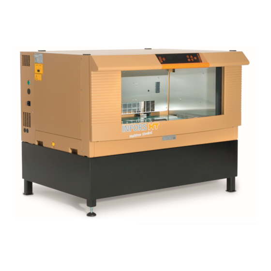
Multitron Standard - Operating Manual Setup and Function 3 Setup and Function 3.1 Setup of the Basic Unit Outside Casing Discharge outlet Operating panel Rubber feet (7x) Serial interface (RS-232) (not visible) Mains connection incl. slot for fuses Door handle... - Page 22 10 Identification of the throw Brief Description The Multitron Standard incubation shaker is used to cultivate micro- organisms in a laboratory environment. The basic version of the de- vice is fitted with a shaker drive and a heater. Depending on the ver- sion of the device, it will come with either a 25 mm or a 50 mm throw.
-
Page 23: Overview Of Versions
3.2 Overview of Versions The Multitron Standard is available in a number of pre-configured packages. Every version of the Multitron Standard is available with a throw of 25 or 50 mm and with or without a cooling system. The tables below provide an overview of the configurations that are available as standard. - Page 24 Multitron Standard - Operating Manual Setup and Function Two units stacked Two units stacked, with 25 or 50 mm throw with- Two units stacked, with 25 or 50 mm throw with out cooling; base, 31 cm side cooling system; base, 31 cm...
-
Page 25: Functions
Multitron Standard - Operating Manual Setup and Function 3.3 Functions 3.3.1 Standard Function - Shaking Mechanics Counterweight Drive belt Electric motor Drive hub The table moves in circles at a speed of 20 to 400 min . It is driven by an electric motor (2), which is connected to the counterweight (1) by a drive belt (3). - Page 26 Multitron Standard - Operating Manual Setup and Function INFORMATION The load weights must be within the permissible range. If the load is too light or too heavy, this will prevent the table from running smoothly, leading to increased wear on the bearings and joints.
-
Page 27: Standard Function - Temperature Control (Heating And Ventilation)
Multitron Standard - Operating Manual Setup and Function 3.3.2 Standard Function – Temperature Control (Heating and Ventilation) Function Temperature is controlled by two cross-flow fans (1), each of which is connected to a downstream heating element. The cross-flow fans en- sure constant air circulation, and keep the temperature distribution in the incubation chamber as constant and gradient-free as possible. -
Page 28: Optional Cooling Function
These are located on the left-hand side of the bracket. The cooling unit is a 2-circuit system with a cool- ing liquid tank, which must be filled with cooling liquid by INFORS HT prior to commissioning. -
Page 29: Interior Lighting
Multitron Standard - Operating Manual Setup and Function INFORMATION For information on the technical data for the cooling system, see chapter 11.3.2 "Temperature Parameter", page 106. 3.4 Interior Lighting The device features interior lighting. The interior lighting is switched on automatically as soon as a button is pressed or the door is opened. -
Page 30: Serial Interface
Multitron Standard - Operating Manual Setup and Function 3.5.2 Serial Interface The device has a serial interface (RS-232, 9-pin). This is located on the right-hand side of the device casing. The serial interface is designed primarily to allow the device to be connected to an external com- puter in order to control it remotely or record data. -
Page 31: Air Vents
Multitron Standard - Operating Manual Setup and Function 3.6.2 Air Vents The device has air vents on both sides and the rear of the casing. When setting up the device, you must ensure that these air vents re- main unobstructed in order to ensure that the exhaust air can be ex- tracted without obstruction and none of the components overheat. -
Page 32: Operating And Indicating Elements
Multitron Standard - Operating Manual Setup and Function 3.8 Operating and Indicating Elements 3.8.1 Power Switch The power switch is located on the left side of the device, towards the rear. As soon as the device is switched on, the power switch lights up green. -
Page 33: Markings On The Device
Multitron Standard - Operating Manual Setup and Function 3.9 Markings on the Device 3.9.1 Identification Plate The identification plate is located on the left-hand side of the device, next to the mains connection. A second identification plate is located at the bottom of the door. -
Page 34: Accessories
Multitron Standard - Operating Manual Accessories 4 Accessories In the following section, the available accessories for the device are described. For special applications, please contact our customer ser- vice for advice (for contact information, see page 2). 4.1 Trays Different trays are available for the device; these can be purchased individually or ordered with the device. -
Page 35: Pre-Fitted Trays
Multitron Standard - Operating Manual Accessories 4.1.2 Pre-Fitted Trays Pre-fitted trays are equipped with one clamp type each. They are used if only a single size of flask is to be used for certain tasks. Unlike the universal table tray, their holders cannot be changed. - Page 36 Multitron Standard - Operating Manual Accessories Tray with steel clamps Fitting identical clamps on the entire tray results in the following ca- pacities: Flask Size Number of Flasks per M Tray 1000 ml 2000 ml 3000 ml 4000 ml 5000 ml...
- Page 37 Multitron Standard - Operating Manual Accessories To ensure the cultures receive the optimum oxygen supply, spacers can be placed between stacked plates. These are available in two var- iants: Ring spacers (10 mm high) are placed on the pins individually.
- Page 38 Multitron Standard - Operating Manual Accessories Tray with clamping assembly There is a quick clamping assembly for affixing microtitre and deep- well plates. Two versions of this clamping assembly are available: Tray with flat clamping assembly (horizontal incubation): The flat clamping assembly is a profile made of sheet metal that is equipped with an angled strip (2).
- Page 39 Multitron Standard - Operating Manual Accessories Technical data for clamping assemblies Description Value Rail material Aluminium Foam rubber material CR rubber Temperature range ≤ 80°C Cleaning Mild neutral cleaning agent Disinfection Commercially available disinfectant Sterilisation Size of microtitre and 85.1 x 127 mm...
-
Page 40: Tray With Sticky Stuff
Multitron Standard - Operating Manual Accessories 4.1.3 Tray with Sticky Stuff ATTENTION If condensate forms on the tray or on the cultivation vessels, the adhesiveness of the Sticky Stuff is no longer guaranteed. As a re- sult, cultivation vessels can become detached from the Sticky Stuff and break. - Page 41 Multitron Standard - Operating Manual Accessories Prior to the shaking process, gently pull on every vessel to en- sure they are all stuck on firmly. If the humidity is too high or the temperatures are too low or if ...
- Page 42 Multitron Standard - Operating Manual Accessories The removed adhesive matting can be reused and can be reapplied after regeneration in water. Adhesive matting that is severely worn due to aging must be replaced. This also applies if a reduction in the adhesive force is detected.
-
Page 43: Clamps And Other Holders
Multitron Standard - Operating Manual Accessories 4.2 Clamps and Other Holders For individual fitting of the universal table tray, various clamps and holders are available. 4.2.1 Clamps Clamps in various sizes are available for equipping a universal table tray. These can be ordered individually and mounted on the universal table tray. -
Page 44: Test Tube Holders
Multitron Standard - Operating Manual Accessories Plastic clamps The following plastic clamps are available: For flask type Volume Erlenmeyer 100 mL 250 mL 500 mL Technical data of the plastic clamps Description Value Material POM Co polymer Fastening screws M4 x 6 Temperature range 65 °C... -
Page 45: Box For Microtitre Plates
Multitron Standard - Operating Manual Accessories ATTENTION The test tube holders adhere extremely strongly to the Sticky Stuff, so that water has to be sprayed underneath the edge of the holder with a syringe in order to remove them. This is done to pre- vent damage to the holder or the tray. - Page 46 Multitron Standard - Operating Manual Accessories Loading the box for microtitre plates To improve transfer of oxygen to the cultures and facilitate the re- moval of the plates, spacers (Quickload spacers) (1) can be placed be- tween the individual layers. Prior to loading, the Quickload spacers must be removed.
- Page 47 Multitron Standard - Operating Manual Accessories Technical data Container with top plate and tray Description Value Dimension 465 x 280 mm Weight 4.23 kg Filter, paper, round, Ø 185 mm Screws for microtitre tray M4 x 8 hexalobular Screws for microtitre box...
-
Page 48: Eve
Thanks to soft sen- sors, additional knowledge can be generated. In addition to INFORS HT products, biotech equipment and analysis devices from third-party manufacturers can also be integrated. In this way, bioprocesses can be controlled, monitored and evaluated en- tirely via one software. -
Page 49: Installation
Multitron Standard - Operating Manual Installation 5 Installation Only the manufacturer’s qualified expert personnel or persons au- thorised by the manufacturer may install and initially commission the device. Hence, the following section only lists the requirements for the installation location to be observed by the provider. -
Page 50: Requirements For The Mains Connection
Multitron Standard - Operating Manual Installation To achieve a stable climate in the incubation chamber and to be able to control the climate accurately, the following installation locations must be avoided: Poorly ventilated recesses or in the exhaust heat air stream of air ... -
Page 51: Minimum Distances To The Device
Multitron Standard - Operating Manual Installation 5.3 Minimum Distances to the Device When setting up the device, the following minimum distances must be observed to ensure adequate ventilation and access to the most important connections: Minimum distances to the device... - Page 52 Multitron Standard - Operating Manual Installation Placing the device under a bench When placing the device under a bench, observe the following points: You must leave a ventilation gap of at least 100 mm between the device and rear wall of the bench to ensure that heat pro- duced by the device can escape.
-
Page 53: Operation
Multitron Standard - Operating Manual Operation 6 Operation 6.1 Switching on the Device ATTENTION The shaker drive can start automatically if the device has not been switched off correctly beforehand. Loose objects in the incubation room can damage the device and the cultivation vessels. -
Page 54: Opening The Door
Multitron Standard - Operating Manual Operation CAUTION If you put a load of more than 20 kg on the door, there is a risk that the device might fall down. This can lead to property damage and injuries. – Do not lean on the door. -
Page 55: Removing The Tray
Multitron Standard - Operating Manual Operation 6.2.2 Removing the Tray The device is fitted with a tray lock to hold the tray securely in place on the table. When the door is opened fully, the lock hooks (1) on the table release the tray. The ejection levers under the table lift the tray out of the table’s lock cones (2). -
Page 56: Inserting The Tray
Multitron Standard - Operating Manual Operation 6.2.3 Inserting the Tray The position of the table is irrelevant when inserting the tray. Proceed as follows: Procedure Open the device door all the way. Place the tray on the door slide rails (4). -
Page 57: Handling Cultivation Flasks Without Removing The Tray
Multitron Standard - Operating Manual Operation ATTENTION If the tray is not held in place securely on the table, the tray may be damaged by the movement of the table inside the machine. – Do not start up the device unless the tray has been inserted correctly and is held in place securely by the lock hooks. -
Page 58: Fitting The Holders
Multitron Standard - Operating Manual Operation 6.2.5 Fitting the Holders ATTENTION The threaded holes of the tray can be damaged if the fastening screws are not screwed straight into the thread: – Place the screws vertically on the drill holes. - Page 59 Multitron Standard - Operating Manual Operation Screw sizes ATTENTION If screws that are too long are used to affix the holders, these will stick out at the bottom of the tray. This has the effect that the tray can no longer be inserted and affixed correctly.
-
Page 60: Tips & Tricks For Loading The Tray
Multitron Standard - Operating Manual Operation 6.2.6 Tips & Tricks for Loading the Tray Observe the following notices when loading the tray: The working volume should not exceed 1/3 of the total volume of the vessel. To ensure a smooth movement, place the cultivation vessels ... - Page 61 Multitron Standard - Operating Manual Operation CAUTION If the loading mass of the table is too high or too low or the load is distributed unevenly, high rotation speeds can cause vibrations. This can result in the device moving uncontrollably and potentially falling off the table.
-
Page 62: Overview Of Display And Operating Elements
Multitron Standard - Operating Manual Operation 6.3 Overview of Display and Operating Elements Timer View box, left parameter symbol Timer active Temperature function symbol parameter symbol Cycle active Setpoint speed function symbol parameter symbol External (EX) View box, right function symbol... -
Page 63: Operating Elements
Multitron Standard - Operating Manual Operation 6.3.1 Operating Elements Operating ele- Designation Function ment On/Off button The On/Off button is used to control the following functions: Switching the device from stand-by mode to active mode. Activating/deactivating the selected parameter. -
Page 64: Display Elements
Multitron Standard - Operating Manual Operation 6.3.2 Display Elements Symbol Designation Meaning Speed Indicates that the speed (setpoint or actual) is being displayed in the corresponding view box. This symbol also indicates that the “Speed” parameter can be adjusted. Temperature Indicates that the temperature (setpoint or actual) is being displayed in the right-hand view box. -
Page 65: View Boxes
Multitron Standard - Operating Manual Operation 6.3.3 View Boxes The current actual values, setpoints, alarm messages and error mes- sages are displayed on one or both of the LED displays using three- letter abbreviations. Left-hand view box (1) Among other factors, the left-hand view box provides information on the speed (actual value or setpoint), error and alarm messages, and operating hours. - Page 66 Multitron Standard - Operating Manual Operation Time information displays Time information is displayed as follows in the view boxes: From 0 to 99 minutes: The time is displayed in minutes ('). Example: 99 minutes From 1 hour, 40 minutes to 9 hours, 50 minutes: ...
-
Page 67: Adjusting, Activating And Deactivating Parameters
Multitron Standard - Operating Manual Operation 6.4 Adjusting, Activating and Deactivating Parameters 6.4.1 Overview of Parameters Rotation speed (RPM) During adjustment, the set rotation speed setpoint in min is dis- played as a whole number. The adjustment range depends on the po- sition of the device in the stack. -
Page 68: Setting The Parameter Setpoint
Multitron Standard - Operating Manual Operation 6.4.2 Setting the Parameter Setpoint To set the setpoint for a parameter, proceed as follows: Press the F button (2) to select the parameter in question. Procedure The right-hand display (1) will show the set setpoint for the pa- rameter. -
Page 69: Activating And Deactivating Parameters
Multitron Standard - Operating Manual Operation 6.4.3 Activating and Deactivating Parameters Activating Parameters To activate a parameter, proceed as follows: Procedure Press the F button (2) to select the parameter in question. The right-hand display (1) will show the set setpoint for the pa- rameter. - Page 70 Multitron Standard - Operating Manual Operation Deactivating Parameters The parameters are deactivated using the same procedure as for acti- vation. Select the parameter you wish to deactivate using the F but- ton, then press the On/Off button to deactivate it. When a parame-...
-
Page 71: Timer Function
Multitron Standard - Operating Manual Operation 6.5 Timer Function ATTENTION If cultivation is started at low temperatures and the temperature is then increased (e.g. when using the timer), condensation can form on the flasks because these are heated up slower than the ambi- ent air. - Page 72 Multitron Standard - Operating Manual Operation One-time change from phase 1 to 2 If the device is programmed using this method, the setpoint settings for the cultivation process parameters will change when the specified time expires. The device will then keep running using the setpoints specified for the second phase until the device is stopped by deac- tivating the parameters.
- Page 73 Multitron Standard - Operating Manual Operation Cyclical changing between phases 1 and 2 If the device is programmed using this method, two different param- eter settings will be repeated on an endless, precisely timed cycle. The two intervals (phase 1 and phase 2) alternate until the cultivation process is stopped manually by deactivating the parameters.
-
Page 74: Programming A One-Time Change
Multitron Standard - Operating Manual Operation 6.5.2 Programming a One-Time Change Programming the timer for a one-time change is a multi-step proce- dure: Set the setpoints (RPM and/or °C) for the first phase using the F button and activate the parameters. - Page 75 Multitron Standard - Operating Manual Operation Setting the Setpoints for Phase 2 (FT Button) Press the FT button (2) to select the parameter in question (RPM or °C). Next phase (FT) function symbol (1) will light up. Press the Plus or Minus button (3) to set the setpoint you want to use for the selected parameter.
-
Page 76: Programming A Cyclical Change
Multitron Standard - Operating Manual Operation INFORMATION Do not set the timer to in the “FT” phase. This will activate cy- clical operation. The device will now run using the setpoints set for the first phase un- Timer active til the set time elapses. The... - Page 77 Multitron Standard - Operating Manual Operation Setting the Setpoints for Phase 1 (F Button) Procedure Press the F button (1) to select the parameter in question (RPM or °C). Press the Plus or Minus button (2) to set the setpoint you want to use for the selected parameter.
- Page 78 Multitron Standard - Operating Manual Operation Setting the Setpoints for Phase 2 (FT Button) Press the FT button (2) to select the parameter in question (RPM or °C). Next phase (FT) function symbol (1) will light up. Press the Plus or Minus button (3) to set the setpoint you want to use for the selected parameter.
-
Page 79: Displaying The Remaining Time
Multitron Standard - Operating Manual Operation The device will now keep running and alternating between the set- points for the first and second phases until it is switched off manually Timer active Cycle active or the setpoints are modified. The... -
Page 80: Aborting The Timer Function
Multitron Standard - Operating Manual Operation 6.5.5 Aborting the Timer Function The timer function can be aborted at any time. To do so, proceed as follows: Procedure Select the timer function using the F button (3). Timer parameter symbol (2) will light up The remaining time will be displayed in the right-hand view box. -
Page 81: Operating The Operating Hours Counter
Multitron Standard - Operating Manual Operation 6.6 Operating the Operating Hours Counter The operating hours counter indicates how long a component of the device has been in operation. The left-hand view box displays the hours in thousands; the right-hand view box displays hours 0 to 999. -
Page 82: Switching On The Interior Lighting
Multitron Standard - Operating Manual Operation 6.7 Switching on the Interior Lighting Automatically switching on the interior lighting The interior lighting is switched on automatically in the following sit- uations: When the device is switched on using the power switch ... -
Page 83: Behaviour In Case Of Interrupted Power Supply
Multitron Standard - Operating Manual Operation INFORMATION The parameter setpoints are stored for approx. one month. To switch off the device, proceed as follows: Procedure Deactivate all active parameters. Press the power switch on the top left of the casing. -
Page 84: Rectifying Faults
The following section describes possible reasons for faults and how to resolve them. If you encounter a fault that cannot be resolved by following the in- structions below, please contact your nearest INFORS HT representa- tive. For service contact details, see page 2. 7.1 Messages in the View Boxes Faults in the device are divided into two categories: Alarms refer to errors in the process, e.g. - Page 85 Multitron Standard - Operating Manual Rectifying Faults The following alarm messages may occur: Alarm message Meaning Temperature too low (actual value < setpoint - 1°C). Possible cause Measures Personnel The parameter has recently No action required. The alarm message will disap- been altered, and the required pear as soon as the setpoint is reached.
- Page 86 Multitron Standard - Operating Manual Rectifying Faults Alarm message Meaning Speed too low (actual value < setpoint - 10 min Possible cause Measures Personnel The load is too heavy, making Reduce the load. Operator the drive too weak or causing it If the drive has overheated, the process can be to overheat.
-
Page 87: Error Messages And Their Meanings
Multitron Standard - Operating Manual Rectifying Faults Alarm message Meaning The device door is open. 7.1.2 Error Messages and their Meanings Error messages are generated when the device develops a fault, e.g. if a component is defective or the table is jammed. Error messages are indicated both acoustically and visually. -
Page 88: Fault Tables
Multitron Standard - Operating Manual Rectifying Faults Temperature control faults Error message Meaning Temperature in incubation chamber too high (> 65°C). Possible cause Measures Personnel Measurement electronics de- Contact your local INFORS HT representative. INFORS HT service tech- fective. nician or licensed dealer... - Page 89 Multitron Standard - Operating Manual Rectifying Faults General faults Fault After activating the power switch, the display and the view boxes do not light up. Possible cause Measures Personnel Power supply to the device in- Operator Check if the plugs are plugged in correctly.
- Page 90 Multitron Standard - Operating Manual Rectifying Faults Faults related to the Rotation speed parameter Fault The table is not moving. Possible cause Measures Personnel The table is blocked by foreign Remove the foreign object. Detach the table from Operator objects.
- Page 91 Re-measuring the temperature only provides reliable information when using calibrated measuring tools, and only if they are used at points specified by INFORS HT. Measurements taken at unde- fined points in the casing will not produce any usable data. For information about temperature measuring, contact your local INFORS HT representative or request a quote for calibrating the parameters.
-
Page 92: Rectifying Faults
Multitron Standard - Operating Manual Rectifying Faults 7.3 Rectifying Faults 7.3.1 Replacing Fuses INFORMATION The fuses may only be replaced by fuses of the same rating. For in- formation concerning the requirements for the fuses see chapter 7.3.1 "Replacing Fuses", page 90. -
Page 93: Returning For Repair
Multitron Standard - Operating Manual Rectifying Faults 7.4 Returning for Repair The provider must return the device or the faulty component part(s) to the manufacturer if, after consulting the service department of the local dealer or the manufacturer, on-site diagnosis and/or repair is not possible. -
Page 94: Maintenance And Cleaning
Multitron Standard - Operating Manual Maintenance and Cleaning 8 Maintenance and Cleaning WARNING To prevent life-threatening electric shocks, always switch off the device and disconnect it from the power supply before carrying out any maintenance or cleaning. 8.1 Maintenance The device requires hardly any maintenance. This reduces the running costs to certain regular checks and cleaning. -
Page 95: Cleaning And Disinfection
Furthermore, the device should be cleaned and disinfected on a regu- lar basis to ensure proper operation. If there are doubts concerning the compatibility of cleaning and disin- fection agents, contact your local INFORS HT representative (see ser- vice contact details on page 2). ATTENTION Insufficient cleaning and disinfection can lead to damage to cul- tures due to contamination. - Page 96 Multitron Standard - Operating Manual Maintenance and Cleaning Splashing water Always use a wet cloth when cleaning the base tray; never pour wa- ter into the tray. Make sure that no water splashes into the bearings. After cleaning the device, especially the interior and the base tray, dry it with a cloth.
-
Page 97: Disinfection
Multitron Standard - Operating Manual Maintenance and Cleaning Remove any foreign bodies and coarse soiling from the base tray by hand. Dry the base tray completely using paper towels. Carefully place the table on its rotary axis. When doing so, align the rotary axis so that the threaded holes on the table are posi- tioned directly over the holes on the rotary axis. -
Page 98: Transport And Storage
Transport and Storage 9 Transport and Storage The inbound delivery and transport to the assembly location are per- formed only by INFORS HT employees or by persons authorised by INFORS HT. Nonetheless it is possible that the provider’s personnel is entrusted with transport tasks in the context of on-site transport. -
Page 99: Disassembly And Disposal
Multitron Standard - Operating Manual Disassembly and Disposal 10 Disassembly and Disposal The device must be disassembled and disposed of in an environmen- tally friendly manner if it is no longer in use. INFORMATION When returning the device for disassembly or disposal, it is re- quired for the safety of all parties involved and because of legal provisions that a lawful declaration of decontamination is present. -
Page 100: Disposal
Local authorities or specialist disposal firms can provide information regarding environmentally acceptable disposal. If no special arrangements have been made for return, INFORS HT units with the required declaration of decontamination can be sent back to the manufacturer for disposal. - Page 101 Multitron Standard - Operating Manual Technical Data and Specifications 11 Technical Data and Specifications 11.1 Dimension Drawings Individual unit with table feet Individual unit with 31 cm base 17 March 2021 Page 99 of 114...
- Page 102 Multitron Standard - Operating Manual Technical Data and Specifications Two units stacked with 31 cm base and side-mounted cooling system Three units stacked with 13 cm base and top cooling system Page 100 of 114 17 March 2021...
- Page 103 Multitron Standard - Operating Manual Technical Data and Specifications 11.2 Specifications of the Basic Device 11.2.1 Weight and Dimensions Mass base unit Description Value Unit Individual unit with 25 mm throw 106 kg Individual unit with 50 mm throw 114 kg...
- Page 104 Multitron Standard - Operating Manual Technical Data and Specifications Interior dimensions (incubation chamber) Description Value Unit Width 925 mm Depth 550 mm Height 390 mm 11.2.2 Electrical Connection and Performance Values Basic device Electrical connection values Description Type 230 V...
- Page 105 Multitron Standard - Operating Manual Technical Data and Specifications 380 W side-mounted cooling system Electrical data Description Value Unit Grid Type 230 V/ 230 V/ 115 V/ 50 Hz 60 Hz 60 Hz Power (max.) 200 W Power consumption 2.6 A...
- Page 106 Multitron Standard - Operating Manual Technical Data and Specifications 11.2.6 Operating Conditions Description Value Unit Temperature range 10 to 30 °C Relative humidity, non-condensing 10 to 85 % Altitude operating location max. 2000 m.a.s.l Pollution degree according to EN 61010-1 Min.
- Page 107 Multitron Standard - Operating Manual Technical Data and Specifications 11.2.8 Operating and Auxiliary Materials ATTENTION Using the wrong auxiliary materials can result in significant dam- age to property. Only use the auxiliary materials in accordance with the table be- low.
- Page 108 Multitron Standard - Operating Manual Technical Data and Specifications 11.3.2 Temperature Parameter Description Value Unit Ventilation 2 heated cross-flow fans Power consumption 750 W Air circulation 360 m Lowest temperature 6 °C (via ambient temperature, without optional cooling) Highest temperature 65 °C...
- Page 109 Multitron Standard - Operating Manual Technical Data and Specifications 11.4.1 Maximum Permissible Rotation Speed Setpoints INFORMATION The following information is based on an ideal tray load of 14 kg made up of standard Erlenmeyer flasks with no baffles, and a fill level of 30 %.
- Page 110 Multitron Standard - Operating Manual Technical Data and Specifications Maximum rotation speed with Sticky Stuff adhesive matting For a detailed description of the maximum permissible rotation speed when using the Sticky Stuff adhesive matting, see chapter 4.1.3 “Tray with Sticky Stuff”, page 38.
- Page 112 Multitron Standard - Operating Manual Index 13 Index Connection values electrical ......102 Coolant ........... 105, 106 Accessories ............32 Cooling clamps ............41 functional description ........26 ® ............... 46 refrigerant ............ 105 microtitre box ..........43 specification ..........102 Sticky Stuff .............
- Page 113 Multitron Standard - Operating Manual Index Dimensions ............101 cooling ............26 shaking ............23 Discharge outlet temperature control ........25 position ............28 Fuses specification ..........102 position ............16 Disinfectant ............. 105 replace ............90 Disinfection ............95 Display elements ..........
- Page 114 Multitron Standard - Operating Manual Index Lighting specification ..........105 Moving .............. 47 position ............27 replacing lighting element ......90 specification ..........103 On/Off button ............ 61 switching on ..........80 Opening the door ..........52 Lo ..............82 Operating conditions ........
- Page 115 Multitron Standard - Operating Manual Index Permitted cultivation vessels ......... 9 table ............... 94 Serial interface ........... 28 Pin allocation for serial interface ......28 Servicing ............92 Placing the device Setpoint on a table ............49 under a table ..........50 achievable, temperature .......
- Page 116 Multitron Standard - Operating Manual Index Switching off ............. 81 programming a one-time change ....72 Top cooling system Switching on ............51 functional description ........26 Symbols specification ..........102 on the operating panel ........62 Transport ............96...
- Page 117 Digitize your bioprocesses The platform software for your bioprocesses – the Bioprocess Platform Software ® Able to do more than just plan, control and analyze your bioprocesses, eve ® software integrates workflows, devices, bioprocess information and big data in a platform that lets you organize your projects in the cloud, no matter how complex they are.
Need help?
Do you have a question about the Multitron Standard and is the answer not in the manual?
Questions and answers