Table of Contents
Advertisement
Quick Links
Advertisement
Table of Contents

Related Manuals for Infors HT Multitron


Summary of Contents for Infors HT Multitron
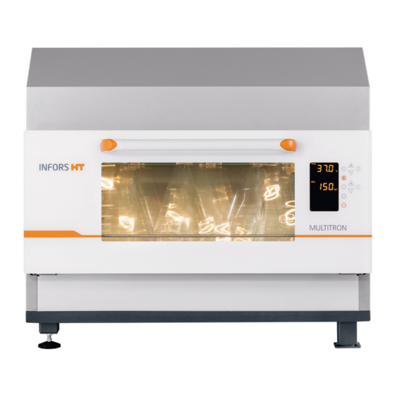
- Page 1 Multitron Operating Manual 2020-08-20 We bring life to your laboratory.
- Page 2 The best Multitron ever Multitron – Rel. 4.0 Incubation Shaker FW: 2.10 Doc-Nr. 77408 - EN V.02.00 - Original This operating manual can also be Infors AG found online at: Headoffice, Switzerland www.infors-ht.com/en/multitron Rittergasse 27 CH-4103 Bottmingen T +41 (0)61 425 77 00 info@infors-ht.com...
-
Page 3: Table Of Contents
Multitron - Operating Manual Table of Contents General Information ............... 7 About this Manual ............7 Explanation of Special Notices ......... 8 1.2.1 Warning Notices ..........8 1.2.2 Other Notices........... 8 Device Identification (Standard Identification Plate) ..9 Declaration of Conformity ..........9 Customer Service and Services ........ - Page 4 Multitron - Operating Manual Table of Contents Openings ..............30 3.4.1 Discharge Outlet ..........30 3.4.2 Ventilation Opening ........31 3.4.3 Air Vents ............31 Interior Lighting............. 32 Frames ................32 Operating and Indicating Elements ........ 33 3.7.1 Power Switch ..........33 3.7.2...
- Page 5 Multitron - Operating Manual Table of Contents LED Lighting ..............52 4.7.1 Setup and Function ........52 4.7.2 Operating the LED Lighting ......52 4.7.3 Specifications and Technical Data ....52 Darkening ..............53 Analog Output .............. 53 4.9.1 Setup and Function ........53 4.9.2...
- Page 6 Multitron - Operating Manual Table of Contents Adjusting, Activating and Deactivating Parameters ..90 7.4.1 Overview about the Parameters ..... 90 7.4.2 Setting the Parameter Setpoints ..... 92 7.4.3 Turning a Parameter On or Off ...... 93 Timer Function .............. 95 7.5.1...
- Page 7 Multitron - Operating Manual Table of Contents Rectifying Faults ..............118 Alarm Messages ............119 8.1.1 Parameter Alarms (High / Low) ..... 119 RESTARTED 8.1.2 Alarm Message ......119 Faults and Error Messages ........... 120 8.2.1 Error Messages Explained ......120 8.2.2...
- Page 8 Multitron - Operating Manual Table of Contents 12.5 Specifications of the Options ........145 12.5.1 Internal Cooling ........... 145 12.5.2 External Cooling .......... 147 12.5.3 Direct Steam Humidification ......148 12.5.4 Pressure Elimination Unit for Direct Steam Humidification ..........149 12.5.5...
-
Page 9: General Information
Multitron - Operating Manual General Information 1 General Information 1.1 About this Manual This manual enables the safe and efficient handling of the device. All the information and instructions in this operating manual comply with the current standards, legal regulations, the latest technological and scientific developments and the knowledge gained from the manufacturer’s many years of experience in this field. -
Page 10: Explanation Of Special Notices
Multitron - Operating Manual General Information 1.2 Explanation of Special Notices 1.2.1 Warning Notices Warning notices in this manual are indicated by a coloured bar and begin with a signal word that signifies the degree of the hazard. DANGER The signal word “DANGER” indicates a dangerous situation that will lead to severe or even fatal injuries if not avoided. -
Page 11: Device Identification (Standard Identification Plate)
Multitron - Operating Manual General Information 1.3 Device Identification (Standard Identification Plate) The identification plate is designed to allow clear identification of the device. It contains the following information: Manufacturer name Designation Category of device Type Device type (name) ... -
Page 12: Safety And Responsibility
Multitron - Operating Manual Safety and Responsibility 2 Safety and Responsibility This section describes general considerations relating to user safety that must be taken into account when working with the device. In the remaining sections, warning notices are used only to highlight particular hazards directly arising from the actions being described in the section in question. -
Page 13: Cultivation Vessels To Be Used
Multitron - Operating Manual Safety and Responsibility Intended use also includes following all the instructions in this man- ual, especially those relating to: The installation site Use of suitable cultivation vessels User qualifications Permissible parameter setpoints ... - Page 14 Multitron - Operating Manual Safety and Responsibility Approved cultivation vessels The device has been designed for use with the following vessels using the holders designed specifically for them: Erlenmeyer flasks up to 5,000 mL made of borosilicate glass (e.g. Schott Duran ®...
-
Page 15: Qualified Personnel
Multitron - Operating Manual Safety and Responsibility 2.3 Qualified Personnel Due to the complexity of the device and the potential risks arising from its operation, the device may only be used by qualified, special- ist personnel. 2.3.1 Provider The term “provider” applies to all persons who are responsible for making the device and the necessary infrastructure available. -
Page 16: Operator
Multitron - Operating Manual Safety and Responsibility Electricians (electrical engineers) Decontamination specialists Repair specialists Specialists in disassembly and (environmentally friendly) disposal Recycling specialists 2.3.3 Operator The “operators” are a specific sub-group of users distinguished by the fact that they work with the device. -
Page 17: Unauthorised Persons
Multitron - Operating Manual Safety and Responsibility 2.4 Unauthorised Persons The term “unauthorised persons” applies to all persons who can ac- cess the work area but are not qualified to use the device in accord- ance with the aforementioned requirements. -
Page 18: Electrical Current
Multitron - Operating Manual Safety and Responsibility 2.6.1 Electrical Current The device is operated electronically. There is an immediate risk of fa- tal injury if contact is made with live parts. The following points must be observed in order to avoid the risk of fatal injury: In case of damage to insulation, disconnect the device from the ... -
Page 19: Danger Due To Hot Surfaces
Multitron - Operating Manual Safety and Responsibility 2.7.1 Danger due to Hot Surfaces For applications that are performed with temperatures over 55 °C, there is a danger of burns on hot surfaces in the interior or on the cultivation vessels. -
Page 20: Pathogenic Organisms
Multitron - Operating Manual Safety and Responsibility 2.7.5 Pathogenic Organisms The device is not approved for cultivation of pathogenic organisms of risk categories 3 and 4. In the context of intended use, it is nonethe- less possible for pathogenic organisms and viruses to be cultivated. -
Page 21: Warning Symbols On The Device
Multitron - Operating Manual Safety and Responsibility 2.9 Warning Symbols on the Device The following warning symbols (stickers) are attached to the device: Position On the housing of the optional direct steam humidification on the rear of the device. Meaning... -
Page 22: Declaration Of Decontamination
Multitron - Operating Manual Safety and Responsibility 2.10 Declaration of Decontamination When returning the device for repair, disassembly or disposal, it is required for the safety of all parties involved and because of legal provisions that a lawful declaration of decontamination is present. -
Page 23: Setup And Function
Multitron - Operating Manual Setup and Function 3 Setup and Function 3.1 Setup of the Basic Unit Exterior Door with window (opens downwards) Cover (optional) Display and operating elements Discharge outlet Door handle Casing 20 August 2020 Page 21 of 158... - Page 24 Multitron - Operating Manual Setup and Function Connections and interfaces MAINS Cable pass-through (optional) Mains connection ( Ethernet Interface ( Slot for fuses (230 V version) or thermal protection switches (115 V version) Status LED ( STATUS, only for service purpose)
- Page 25 Pt100 temperature sensor Slide rail Brief description The Multitron incubation shaker is used to cultivate micro-organisms in a laboratory environment. The basic version of the device is fitted with a shaker drive and a heater. Depending on the version of the device, it will come with either a 3 mm, 25 mm or 50 mm throw.
- Page 26 Multitron - Operating Manual Setup and Function Stacking devices If necessary, up to three units can be stacked to save space. The de- vices can also be stacked subsequently but stacking must be per- formed by the manufacturer’s qualified expert personnel or persons authorised by the manufacturer.
-
Page 27: Basic Functions
Multitron - Operating Manual Setup and Function 3.2 Basic Functions The standard features of the device include the shaking function (pa- Temp rameter ) and temperature control (parameter 3.2.1 Standard Function Shaking Counterweight Drive hub Tray ejection The shaking table moves in circles. It is driven by an electric motor, which is connected to the device’s flywheel by a drive belt. - Page 28 Multitron - Operating Manual Setup and Function Table The table is used to hold the 85 x 47 cm (type M) tray, various ver- sions of which are available. Bars on the sides, two stops and two tapered plugs ensure that the tray is positioned correctly.
- Page 29 Multitron - Operating Manual Setup and Function Adjustable throw If the device features an adjustable throw, there are four possible po- sitions for the eccentric throw: 12.5 mm 19 mm 25 mm 50 mm The counterweights are also adjustable to reduce vibrations during operation.
-
Page 30: Standard Function Temperature Control (Heating)
Multitron - Operating Manual Setup and Function 3.2.2 Standard Function Temperature Control (Heating) Finned heating element and radial fans (in back Pt100 temperature sensor wall, not visible) The temperature in the incubation chamber is regulated using a Pt100 temperature sensor with a PID controller. Four radial fans en- sure constant air circulation and keep the temperature distribution in the incubation chamber as constant and gradient-free as possible. -
Page 31: Connections And Interfaces
Multitron - Operating Manual Setup and Function 3.3 Connections and Interfaces 3.3.1 Mains Connection The mains connection is located on the right side of the device. Three different versions of the device are available for different mains volt- ages: 230 V 50 Hz ... -
Page 32: Ethernet Interface
Multitron - Operating Manual Setup and Function 3.3.3 Ethernet Interface The device is provided with an Ethernet interface (RJ45 socket). The socket is located on the right side of the device. The Ethernet interface can be used to integrate the device into a net- work and thus control it using a remote computer. -
Page 33: Ventilation Opening
Multitron - Operating Manual Setup and Function 3.4.2 Ventilation Opening An opening for ventilation of the interior is located in the top centre of the rear of the casing. The purpose of ventilation is to supply bac- terial cultures with oxygen from the air. -
Page 34: Interior Lighting
Multitron - Operating Manual Setup and Function 3.5 Interior Lighting The device features two LED spots to illuminate the incubation cham- ber. These are located in the door area on the inside of the casing. The interior lighting is switched on automatically as soon as a button is pressed or the door is opened. -
Page 35: Operating And Indicating Elements
Multitron - Operating Manual Setup and Function High base, 41 cm Individual units and devices stacked in pairs can be fitted with a 41 cm base. The base has an adjustable foot that can be used to level the device. -
Page 36: Markings On The Device
Multitron - Operating Manual Setup and Function 3.8 Markings on the Device 3.8.1 Identification Plate The identification plates for identifying the device are located on the right side of the casing, directly above the mains connection and on the front of the door. -
Page 37: Options
Multitron - Operating Manual Options 4 Options To adapt the device to the specific usage scenarios, the device can be enhanced with various options. The options can be ordered at the same time as the device or can be fitted at a later stage. For detailed information on the options as well as advice, contact our customer service (for contact information, see page 2). - Page 38 Multitron - Operating Manual Options The device can be equipped with an internal cooling unit. The cooling unit can either be placed in a bracket on the incubation shaker or in the high base (900 W version only). The cooling unit is available in two different versions: Version with 900 W cooling capacity (one compressor) ...
-
Page 39: External Cooling
Multitron - Operating Manual Options 4.1.2 External Cooling Setup and function If you are planning to connect the device to an external cooling sys- tem, a cooling register and a control valve are installed. A control valve opens when necessary to allow cooling liquid to flow through the cooling register. -
Page 40: Operating The Cooling Unit
Multitron - Operating Manual Options 4.1.3 Operating the Cooling Unit Cooling is operated using the Temperature parameter. The top alpha- °C Temp numeric display shows the actual value in with the symbol The only way to see that cooling is used is that temperatures below the ambient temperature can be reached in the incubation chamber. -
Page 41: Direct Steam Humidification
Multitron - Operating Manual Options 4.2 Direct Steam Humidification Part of the medium can evaporate, in particular in case of small vol- umes of work (e.g. when using microtitre and deep well plates) and long cultivation processes. To reduce evaporation, the device can be fitted with a direct steam humidification. -
Page 42: Connection Conditions
Multitron - Operating Manual Options Observe the following points when using the direct steam humidifica- tion: The direct steam humidification only works actively in one direc- tion. It only humidifies; it does not dehumidify. The direct steam humidification is optimised for operation at ... -
Page 43: Operating The Direct Steam Humidification
Multitron - Operating Manual Options 4.2.3 Operating the Direct Steam Humidification Humidity The direct steam humidification is operated using the rameter. The bottom of the alphanumeric display shows the value in (relative humidity) with the symbol Humid After switching on the parameter, it takes approx. 5 minutes for the steam generator to heat up. -
Page 44: Pressure Elimination Unit For Direct Steam Humidification
Multitron - Operating Manual Options 4.3 Pressure Elimination Unit for Direct Steam Humidification The pressure elimination unit is used to connect the optional direct steam humidification to a pressurized water line (e.g. VE water line) with a pressure of up to 6 bar. -
Page 45: Cleaning The Pressure Elimination Unit
Multitron - Operating Manual Options The pressure elimination unit consists mainly of a stainless steel vessel (E), which is filled with water via the operator's pressurized water line (D). If the level in the vessel decreases, the float (G) is lowered and thus opens the valve (F). - Page 46 Multitron - Operating Manual Options Remove the level sensor: Disconnect the mains cable of the level sensor. Disconnect the connection cable on the solenoid valve. Loosen the wing nut of the clamp. Open and remove the clamp. Remove the level sensor.
-
Page 47: Autoclaving The Pressure Elimination Unit
Multitron - Operating Manual Options ATTENTION Aggressive cleaning agents, solvents and abrasive cleaning utensils (hard sponges, brushes) can scratch surfaces, damage the equip- ment and impair its function. In addition, do not use cleaning agents containing chlorine, as stainless steel is not resistant to substances containing chlorine. - Page 48 Multitron - Operating Manual Options Prerequisites: The level sensor is dismounted. The water supply line is disconnected. The lid of the vessel is mounted. INFORMATION The solenoid valve is closed in de-energized state (normaly closed, NC). It is therefore not mandatory to fit a blind cap to the water connection.
-
Page 49: Dimensions
Multitron - Operating Manual Options 4.3.4 Dimensions Dimensions Multitron with pressure elimination unit Dimensions for autoclaving 4.3.5 Specifications and Technical Data For detailed descriptions of the technical data, see chapter 12.5.4 "Pressure Elimination Unit for Direct Steam Humidification", page 149. -
Page 50: Co 2 Control
Multitron - Operating Manual Options 4.4 CO Control The optional CO control makes it possible to enrich the atmosphere in the incubation chamber by 0 to 20 % CO . The CO control option is particularly suited to cultivation of mammalian cells and algae be-... -
Page 51: Connection Conditions
Multitron - Operating Manual Options The CO content in the incubation chamber is measured and regu- lated using a CO sensor. This is mounted on the right side of the back wall of the incubation chamber. 4.4.2 Connection Conditions The in-house gas supply and connecting hose must meet the follow-... -
Page 52: Uv Decontamination
Multitron - Operating Manual Options 4.5 UV Decontamination 4.5.1 Setup and Function The optional UV decontamination is used to kill microorganisms in the air in the incubation chamber. The option consists of two UV de- contamination lamps on the rear wall of the housing. These emit high-energy UV radiation of 253.7 nm. -
Page 53: Removable Shelf
Multitron - Operating Manual Options 4.6 Removable Shelf The removable shelf (approx. 865 mm x 490 mm allows static incu- bation in climatic conditions almost identical to the cultivation flasks. The removable shelf can be inserted at three different heights into the rails mounted on the side walls in the incubation chamber. -
Page 54: Led Lighting
Multitron - Operating Manual Options 4.7 LED Lighting The device can be equipped with a LED lighting option. This illumi- nates the surface of the table at an adjustable light intensity. For ex- ample, the LED lighting option can be used to cultivate phototrophic cells. -
Page 55: Darkening
Multitron - Operating Manual Options 4.8 Darkening The glass panel of the door can be covered with white adhesive film on the inside. This is used for darkening as well as to ensure better light distribution in the incubation chamber when using LED lighting. -
Page 56: Cable Pass-Through
Multitron - Operating Manual Options 4.10 Cable Pass-through 4.10.1 Setup and Function A pass-through for cables or hoses can be installed on the right side of the casing. This can be used to guide additional sensors or gassing into the incubation chamber. -
Page 57: Using The Cable Pass-Through
Multitron - Operating Manual Options 4.10.2 Using the Cable Pass-through To correct insert cables and hoses into the incubation chamber, pro- ceed as follows: WARNING If an external device that is supplied with mains power is operated on the table whilst it is operating, there is a risk that the cable might break or get jammed. -
Page 58: Antimicrobial Coating
Multitron - Operating Manual Options 4.11 Antimicrobial Coating The housing of the device can be provided with an antimicrobial coating if requested. This contains a lacquer additive made of pure metallic silver that reliably kills microorganisms that come into con- tact with the surface. -
Page 59: Accessories
Multitron - Operating Manual Accessories 5 Accessories In the following section, the available accessories for the device are described. For special applications, please contact our customer ser- vice for advice (for contact information, see page 2). 5.1 Trays Different trays are available for the device; these can be purchased individually or ordered with the device. -
Page 60: Pre-Fitted Trays
Multitron - Operating Manual Accessories 5.1.2 Pre-Fitted Trays Pre-fitted trays are equipped with one clamp type each. They are used if only a single size of flask is to be used for certain tasks. Unlike the universal table tray, their holders cannot be changed. - Page 61 Multitron - Operating Manual Accessories Tray with steel clamps Fitting identical clamps on the entire tray results in the following ca- pacities: Flask Size Number of Flasks per M Tray 1000 ml 2000 ml 3000 ml 4000 ml 5000 ml...
- Page 62 Multitron - Operating Manual Accessories Ring spacers (10 mm high) are placed on the pins individually. Depending on the type of tray loading, this makes it possible to remove individual plates or stacks of plates. Quickload spacers are long plastic strips (4 mm high) that ...
- Page 63 Multitron - Operating Manual Accessories Tray with flat clamping assembly (horizontal incubation): The flat clamping assembly is a profile made of sheet metal that is equipped with an angled strip (2). On the other side, there is an edge featuring a foam rubber strip (3). There are two spacers on the edge (1) for positioning microtitre plates or deep-well plates.
- Page 64 Multitron - Operating Manual Accessories Technical data for clamping assemblies Description Value Rail material Aluminium Foam rubber material CR rubber Temperature range ≤ 80°C Cleaning Mild neutral cleaning agent Disinfection Commercially available disinfectant Sterilisation Size of microtitre and 85.1 x 127 mm...
-
Page 65: Tray With Sticky Stuff
Multitron - Operating Manual Accessories 5.1.3 Tray with Sticky Stuff ATTENTION If condensate forms on the tray or on the cultivation vessels, the adhesiveness of the Sticky Stuff is no longer guaranteed. As a re- sult, cultivation vessels can become detached from the Sticky Stuff and break. - Page 66 Multitron - Operating Manual Accessories Prior to the shaking process, gently pull on every vessel to en- sure they are all stuck on firmly. If the humidity is too high or the temperatures are too low or if ...
-
Page 67: Clamps And Other Holders
Multitron - Operating Manual Accessories INFORMATION Due to limited resistance to disinfectants as well as the risk of un- intentional detaching of flasks, Sticky Stuff is not suitable for culti- vating pathogenic microorganisms. Maximum rotation speed with Sticky Stuff To ensure that the flasks do not detach from the adhesive matting, the maximum permissible speed is limited when using adhesive mat- ting. -
Page 68: Clamps
Multitron - Operating Manual Accessories 5.2.1 Clamps Clamps in various sizes are available for equipping a universal table tray. These can be ordered individually and mounted on the universal table tray. Stainless steel clamps The following stainless steel clamps are available:... -
Page 69: Test Tube Holders
Multitron - Operating Manual Accessories 5.2.2 Test Tube Holders Test tube holders are used to securely affix different sized test tubes. Test tube holders can be screwed onto a universal table tray or placed on Sticky Stuff adhesive matting. The following test tube holders are available (details and special types on request): For long test tubes, Ø... -
Page 70: Box For Microtitre Plates
Multitron - Operating Manual Accessories 5.3 Box for Microtitre Plates Overview The box for microtitre plates is used for low-vapour cultivation of mi- crotitre plates and deep well plates. It protects cultures from drafts in the incubation chamber and also offers a stable container in which cultures can be transported. - Page 71 Multitron - Operating Manual Accessories Loading the box for microtitre plates To improve transfer of oxygen to the cultures and facilitate the re- moval of the plates, spacers (Quickload spacers) (1) can be placed be- tween the individual layers. Prior to loading, the Quickload spacers must be removed.
- Page 72 Multitron - Operating Manual Accessories Technical data Container with top plate and tray Description Value Dimension 465 x 280 mm Weight 4.23 kg Filter, paper, round, Ø 185 mm Screws for microtitre tray M4 x 8 hexalobular Screws for microtitre box...
-
Page 73: Eve
Thanks to soft sen- sors, additional knowledge can be generated. In addition to INFORS HT products, biotech equipment and analysis devices from third-party manufacturers can also be integrated. In this way, bioprocesses can be controlled, monitored and evaluated en- tirely via one software. -
Page 74: Installation
Multitron - Operating Manual Installation 6 Installation Only the manufacturer’s qualified expert personnel or persons au- thorised by the manufacturer may install and initially commission the device. Hence, the following section only lists the requirements for the installation location to be observed by the provider. -
Page 75: Requirements For The Mains Connection
Multitron - Operating Manual Installation To achieve a stable climate in the incubation chamber and to be able to control the climate accurately, the following installation locations must be avoided: Poorly ventilated recesses or in the exhaust heat air stream of air ... -
Page 76: Minimum Distances To The Device
Multitron - Operating Manual Installation 6.3 Minimum Distances to the Device When setting up the device, the following minimum distances must be observed to ensure adequate ventilation and access to the most important connections: Minimum distances base unit Minimum distances with options (analog output and direct... - Page 77 Multitron - Operating Manual Installation Placing the device under a table When placing the device under a table, observe the following: You must leave a ventilation gap of at least 100 mm between the device and rear wall of the table to ensure heat produced by the device can escape.
-
Page 78: Operation
Multitron - Operating Manual Operation 7 Operation 7.1 Switching on the Device ATTENTION The shaker drive can start automatically if the device has not been switched off correctly beforehand. Loose objects in the incubation room can damage the device and the cultivation vessels. -
Page 79: Inserting And Removing The Tray
Multitron - Operating Manual Operation The shaker drive and all other parameters will start up again auto- matically as soon as the door is closed. INFORMATION If you wish to stop the shaker drive slowly, e.g. to avoid culture liq-... - Page 80 Multitron - Operating Manual Operation Device with 3 mm throw: To insert the tray, manually move it into the incubation chamber all the way to the limit stop and lower it into the locking cones (1) in the front section of the table. The tray then has to be affixed to the table using a knurled screw (2).
- Page 81 Multitron - Operating Manual Operation Place the tray on the door slide rails. Push the tray between the guide rails over the front stop bar up to the limit stop at the back of the incubation chamber. The tray must audibly click into place behind the front stop bar.
-
Page 82: Fitting The Holders
Multitron - Operating Manual Operation Tray cannot be inserted If you are unable to insert the tray correctly, perform the following checks: Remove the tray and check it is not twisted or bent. Check the incubation chamber for foreign matter and other ob- ... - Page 83 Multitron - Operating Manual Operation Procedure Loosen flat gaskets. Position the holder on the tray. Centre a screw on the threaded hole in the tray and screw it in loosely. It must still be possible to turn the holder. Align the holder so that all screws are vertical above the respec- tive threaded hole in the tray.
-
Page 84: Tips & Tricks For Loading The Tray
Multitron - Operating Manual Operation 7.2.4 Tips & Tricks for Loading the Tray Observe the following notices when loading the tray: The working volume should not exceed 1/3 of the total volume of the vessel. To ensure a smooth movement, place the cultivation vessels ... - Page 85 Multitron - Operating Manual Operation Stacked devices With devices stacked in three, very low loads (< 10 kg per unit) and high rotation speeds (> 300 min ) at the same time can result in vi- brations occur. In this case it is recommended to place additional cul- tivation vessels filled with water on the tray.
-
Page 86: Overview About The Display Und Controls
Multitron - Operating Manual Operation 7.3 Overview about the Display und Controls Complete display area Complete operating panel Upper display: Parameter setpoints and actual Upper operating panel: For setting the temperature light temperature light values ( ); time (timer 1) -
Page 87: Display Area
Multitron - Operating Manual Operation 7.3.1 Display Area The Complete display area The display area is dominated by the two alphanumeric displays by which the setpoint and actual values of the parameters as well as dif- ferent messages are communicated. -
Page 88: Signs And Messages Regarding The Timer Function
Multitron - Operating Manual Operation 7.3.2 Signs and Messages Regarding the Timer Function In the upper and lower display area All signs and symbols in connection with the timer information – ex- cept the duration which needs to be entered – light up in blue. -
Page 89: Error, Warning, And Alarm Signs
Multitron - Operating Manual Operation 7.3.3 Error, Warning, and Alarm Signs Between the upper and the lower alphanumeric display area there is a separate field with various signs associated with error, warning, and alarm messages. The big red general symbol for warnings lights up in connection with error messages and alarms to emphasise the importance of the mes- sage. -
Page 90: Operating Panel
Multitron - Operating Manual Operation 7.3.4 Operating Panel The various keys on the operating panel serve to select and set the parameters, timers and other functions and modes. On the panel there are selection keys in orange (parameters, operator mode) and in blue (timer function) as well as white keys for the setting. - Page 91 Multitron - Operating Manual Operation Keys for setting After tapping the SET key the parameter setpoints or the duration for the timer can be entered. Setpoint In the according display area the sign lights up. With the Plus key the values for the parameters or the time are in- creased.
-
Page 92: Adjusting, Activating And Deactivating Parameters
Multitron - Operating Manual Operation 7.4 Adjusting, Activating and Deactivating Parameters Has the device been turned on via the power switch and is the initiali- sation process terminated, the device is ready for getting pro- grammed. 7.4.1 Overview about the Parameters... - Page 93 Multitron - Operating Manual Operation Rotation speed (RPM) rotation speed The parameter ) belongs to the standard scope of delivery. When entering the setpoint value for the rotation speed it is shown in rpm (min ) with an accuracy of one whole number.
-
Page 94: Setting The Parameter Setpoints
Multitron - Operating Manual Operation 7.4.2 Setting the Parameter Setpoints To set the parameter setpoints, proceed as follows: Procedure Select the desired pair of parameters with the Select key (1). The alphanumeric display field shows the current values of the selected parameter pair. -
Page 95: Turning A Parameter On Or Off
Multitron - Operating Manual Operation 7.4.3 Turning a Parameter On or Off Turning a parameter on To turn a parameter on, proceed as follows: INFORMATION Steps 1 and 2 can be omitted, if the parameter is turned on di- rectly after entering the setpoint value. - Page 96 Multitron - Operating Manual Operation INFORMATION It takes a while for the parameters to reach the entered setpoint High value. The sign lights up, if the current value of a pa- rameter is above respectively below its setpoint value. Turning a parameter off Turning off a parameter is carried out the same way as switching on a parameter.
-
Page 97: Timer Function
Multitron - Operating Manual Operation 7.5 Timer Function 7.5.1 Overview The timer function allows you to programme defined sequences (e.g. changing parameter setpoints after a defined time period or delaying the start of the cultivation process). The timer can be programmed in... - Page 98 Multitron - Operating Manual Operation One-time change from phase 1 to phase 2 If the device is programmed in this way, the two different parameter settings for the cultivating process change after the given period of time. The device then runs using the settings for the second phase until it is stopped manually by turning the parameters off.
- Page 99 Multitron - Operating Manual Operation Cyclical change between phase 1 and phase 2 If the device is programmed in this way, two different parameter set- tings are repeated in an endless, precisely timed cycle. The two time intervals (Phase 1 and Phase 2) alternate until the cultivating process is stopped manually by turning the parameters off.
- Page 100 Multitron - Operating Manual Operation Schematic overview of the timer programming Page 98 of 158 20 August 2020...
-
Page 101: Programming The Timer - Single Change
Multitron - Operating Manual Operation 7.5.2 Programming the Timer - Single Change Programming the timer for a single change consists of the following steps: Entering the time for the first phase. Entering the setpoint values for the first phase and switching on the parameters. - Page 102 Multitron - Operating Manual Operation Tap the ON/OFF key in the upper setting key area to activate Time 1 the timer ( On the upper alphanumeric display the message appears for a very short time and then the time entered is shown...
- Page 103 Multitron - Operating Manual Operation Checking the timer for the second phase Tap the TIMER key to get to the time settings for the second Time 2 phase ( On the lower alphanumeric display appears the time entered last or 00:00 if no time has been entered.
- Page 104 Multitron - Operating Manual Operation 10. Tap the Plus or Minus key in the corresponding setting key area to set the desired setpoint values and switch the parameters on using the ON/OFF key. Starting the timer 11. Tap the TIMER key when all settings for the second phase are...
- Page 105 Multitron - Operating Manual Operation 13. Tap the Select key to quit the timer programming mode. If the Select key is not used, the display changes to the normal operating mode automatically after 60 seconds. The displays now show the current values of the integral param-...
-
Page 106: Programming The Timer - Cyclic Change
Multitron - Operating Manual Operation 7.5.3 Programming the Timer - Cyclic Change Programming the timer for a cyclic change consists of the following steps: Time 1 Entering the time for the first phase ( Entering the setpoint values for the first phase and switching on the parameters. -
Page 107: Changing Timer Settings During Activated Timer Function
Multitron - Operating Manual Operation 7.5.4 Changing Timer Settings during Activated Timer Function If it is required to change the duration of the time intervals, both tim- ers can be reprogrammed. To change the setting of the timers pro- ceed as follows: Tap the TIMER key to select the timer function. -
Page 108: Changing Parameter Setpoint Values During Activated Timer Function
Multitron - Operating Manual Operation 7.5.5 Changing Parameter Setpoint Values during Activated Timer Function Especially during long cultivating processes in the cycle mode it might be required to change the parameter settings after a certain time. Parameters of the active phase... -
Page 109: Stopping The Timer Function
Multitron - Operating Manual Operation Parameters of any phase Use the TIMER key to select the desired phase. Procedure After taping the TIMER key once, the remaining time of the active phase appears with the message After tapping the TIMER key twice, the time entered for ... - Page 110 Multitron - Operating Manual Operation Tap the ON/OFF key in the lower operating key are to turn the timer function off. On the alphanumeric displays the messages Strt (upper) and Setpoint (lower) appear. In the lower display area the white sign is lit up.
-
Page 111: Using Eve ® To Operate The Device
Multitron - Operating Manual Operation 7.6 Using eve ® to Operate the Device INFORMATION For detailed information on how to use eve to operate the device, ® refer to the documentation supplied with eve ® The device comes with the option of being operated from an external computer via the Ethernet interface. - Page 112 Multitron - Operating Manual Operation Requirements To ensure the device can be operated via the Ethernet interface, the function must be activated in the settings menu. Here, you can Auto choose between the options (read only) and (read and write) (see chapter 7.7.9 "Setting up Data Exchange via Ethernet", page...
-
Page 113: Settings Menu (Option Function)
Multitron - Operating Manual Operation 7.7 Settings Menu (Option Function) The settings menu enables you to adjust the main device settings. To open the device’s settings menu, proceed as follows: Procedure Tap the OPTION key for at least 2 seconds. -
Page 114: Setting The Upper Limit For The Temperature
Multitron - Operating Manual Operation 7.7.2 Setting the Upper Limit for the Temperature Temp Setpoint High Top display: The maximum temperature that can be entered as a setpoint can be Setpoint restricted. To do so, tap the SET key (the sign... -
Page 115: Activating Or Deactivating The Key Pad Lock (With A Pin)
Multitron - Operating Manual Operation INFORMATION When opening the door of the device, the table is stopped with the maximum brake force, regardless which brake force is set. 7.7.5 Activating or Deactivating the Key Pad Lock (with a PIN) Top display: To prevent unauthorised persons making entries on the operating panel, the key pad can be locked using a PIN. -
Page 116: Setting The Interior Lighting
Multitron - Operating Manual Operation 7.7.7 Setting the Interior Lighting Light Top display: The behaviour of the interior lighting can be set. Setpoint To do so, tap the SET key (the sign appears) and then use the ON/OFF key to select the desired behaviour. -
Page 117: Setting Up Data Exchange Via Ethernet
Multitron - Operating Manual Operation 7.7.9 Setting up Data Exchange via Ethernet EXTERN Wireless Top display: You can set whether and in which direction data can be sent via the Ethernet interface. To do so, tap the SET key (the writing Setpoint appears) and then use the ON/OFF key to select the desired setting. -
Page 118: Humidity - Switch On/Off High Alarm
Multitron - Operating Manual Operation 7.7.12 Humidity – Switch On/Off High Alarm Top display: ALARM Humid High Bottom display: Humidity The High alarm of the parameter can be switched on or off. If the alarm is switched off, no alarm is triggered if the humidity ex- ceeds the upper limit value. -
Page 119: Switching Off The Device
Multitron - Operating Manual Operation 7.9 Switching Off the Device ATTENTION Parameters, that have not been switched off prior to switching off the device, are automatically activated when the device is switched on. This can lead to damages to the device and cultivation vessels. -
Page 120: Rectifying Faults
Multitron - Operating Manual Rectifying Faults 8 Rectifying Faults The following section describes possible reasons for faults and how to rectify them. Fault messages ALARM A distinction is made between alarms ( ) and error messages ERROR Alarms refer to errors in the process, for example, when the ... -
Page 121: Alarm Messages
Multitron - Operating Manual Rectifying Faults 8.1 Alarm Messages 8.1.1 Parameter Alarms (High / Low) A parameter alarm is triggered if the actual value of a parameter de- viates too much from the setpoint after a specified waiting time. In the example on the left the temperature is too high. -
Page 122: Faults And Error Messages
Multitron - Operating Manual Rectifying Faults 8.2 Faults and Error Messages 8.2.1 Error Messages Explained The faults listed here, the causes of which are described using error messages, can generally not be resolved by users. One of the manu- facturer’s service technicians needs to be consulted if these messages appear. - Page 123 Multitron - Operating Manual Rectifying Faults Bottom In conjunction with the rotation speed parameter symbol lights up) Error, Heat The control of the motor has overheated because of excessively high rotation speed or excess loading. Once the device has cooled down it can be restarted.
- Page 124 Multitron - Operating Manual Rectifying Faults Bottom In combination with the CO parameter symbol lights up) Error, Sensor The CO sensor is not returning any readings (CO sensor not con- nected or defective). Error, Control The actual CO value does not rise (CO supply interrupted, pressure too low or door not closed correctly).
-
Page 125: Fault Tables
Activate interior lighting (see chapter 7.7.7, page Interior lighting is deactivated. Operator 114). The LED unit of the interior Contact your local INFORS HT representative. INFORS HT service tech- lighting is defective. nician or licenced dealer 20 August 2020 Page 123 of 158... - Page 126 Operator objects. 129). INFORS HT service tech- The drive belt has torn. Contact your local INFORS HT representative. nician or licenced dealer The motor is defective. Contact your local INFORS HT representative. INFORS HT service tech- nician or licenced dealer The (open-loop) control of the Contact your local INFORS HT representative.
- Page 127 The re-measuring of the temperature only provides reliable infor- mation when calibrated measuring tools are used and only if they are used at points specified by INFORS HT. A measurement at un- defined positions in the casing will not produce any usable data.
- Page 128 Operator Inlet pressure or flow too low. Increase inlet pressure or flow. Operator valve closed or blocked. Contact your local INFORS HT branch. INFORS HT service tech- nician or licenced dealer Fault concentration too high (deviation < 1%). Possible cause...
-
Page 129: Replacing Fuses
Multitron - Operating Manual Rectifying Faults 8.3 Replacing Fuses INFORMATION The fuses may only be replaced by fuses of the same rating. For in- formation concerning the requirements for the fuses see chapter 12.3 "Specifications of the Basic Unit", page 140. -
Page 130: Maintenance And Cleaning
Multitron - Operating Manual Maintenance and Cleaning 9 Maintenance and Cleaning WARNING To prevent life-threatening electric shocks, always switch off the device and disconnect it from the power supply before carrying out any maintenance or cleaning. 9.1 Maintenance The device requires hardly any maintenance. This reduces the running costs to certain regular checks and cleaning. -
Page 131: Cleaning And Disinfection
Furthermore, the device should be cleaned and disinfected on a regu- lar basis to ensure proper operation. If there are doubts concerning the compatibility of cleaning and disin- fection agents, contact your local INFORS HT representative (see ser- vice contact details on page 2). ATTENTION Insufficient cleaning and disinfection can lead to damage to cul- tures due to contamination. - Page 132 Multitron - Operating Manual Maintenance and Cleaning Splashing water Always use a wet cloth when cleaning the base tray; never pour wa- ter into the tray. Make sure that no water splashes into the bearings. After cleaning the device, especially the interior and the base tray, dry it with a cloth.
- Page 133 Multitron - Operating Manual Maintenance and Cleaning Procedure Open the device door all the way. Remove the tray. Turn off the power switch and pull out the plug. Loosen the three screws (hexalobular M6x12) in the centre of ta- ble using the screwdriver provided.
-
Page 134: Disinfection
Multitron - Operating Manual Maintenance and Cleaning 9.2.2 Disinfection Only use quaternary ammonium compounds for wipe-down disinfec- tion. As a tried as tested disinfectant, we recommend Fermacidal D2. ATTENTION Heat (temperatures above 80 °C), aggressive disinfectants such as chlorine bleach and UVC radiation can damage the device and sig- nificantly limit the function and useful life of the machine. -
Page 135: Transport And Storage
Transport and Storage 10 Transport and Storage The inbound delivery and transport to the assembly location are per- formed only by INFORS HT employees or by persons authorised by INFORS HT. Nonetheless it is possible that the provider’s personnel is entrusted with transport tasks in the context of on-site transport. -
Page 136: Disassembly And Disposal
Multitron - Operating Manual Disassembly and Disposal 11 Disassembly and Disposal The device must be disassembled and disposed of in an environmen- tally friendly manner if it is no longer in use. INFORMATION When returning the device for disassembly or disposal, it is re- quired for the safety of all parties involved and because of legal provisions that a lawful declaration of decontamination is present. -
Page 137: Disposal
Local authorities or specialist disposal firms can provide information regarding environmentally acceptable disposal. If no special arrangements have been made for return, INFORS HT units with the required declaration of decontamination can be sent back to the manufacturer for disposal. -
Page 138: Technical Data And Specifications
Multitron - Operating Manual Technical Data and Specifications 12 Technical Data and Specifications 12.1 Dimension Drawings Two units stacked with high base frame and the following options: Low cover (1) control (2) Analog output (3) Direct steam humidification (4) ... - Page 139 Multitron - Operating Manual Technical Data and Specifications Three units stacked with low base frame and the following options: Top cooling (1) control (2) Analog output (3) Direct steam humidification (4) All dimensions in mm 20 August 2020...
-
Page 140: Connections
Multitron - Operating Manual Technical Data and Specifications 12.2 Connections Two units stacked with high base frame: Demineralised water in (hose connector DN06) / Coolant in (hose connector DN10) / max. 4 bar max. 0.3 bar Coolant out (hose connector DN10) / pressure- less Discharge outlet (female thread G1/4‘‘) - Page 141 Multitron - Operating Manual Technical Data and Specifications Three units stacked with low base frame: All dimensions in mm 20 August 2020 Page 139 of 158...
-
Page 142: Specifications Of The Basic Unit
Multitron - Operating Manual Technical Data and Specifications 12.3 Specifications of the Basic Unit 12.3.1 Weight and Dimensions Weight Description Value Unit Single unit (3 mm throw) 129 kg Single unit (25 mm throw) 137 kg Single unit (50 mm throw) -
Page 143: Electrical Connection And Power Values
Multitron - Operating Manual Technical Data and Specifications Interior dimensions (incubation chamber) Description Value Unit Width 935 mm Depth 570 mm Height (without LED lighting) 380 mm Height (with LED lighting) 350 mm 12.3.2 Electrical Connection and Power Values Description... -
Page 144: Interior Lighting
Multitron - Operating Manual Technical Data and Specifications 12.3.4 Interior Lighting Description Value Unit Type LED spot Current consumption 350 mA Power 12.3.5 Material Component Material Casing Polyurethane (PUR-IHS) with foam protection Door PUR-IHS, safety glass Cover plate temperature control Stainless steel (1.4301-2B) -
Page 145: Protection Type
Multitron - Operating Manual Technical Data and Specifications 12.3.8 Protection Type Description Value IP protection type 20 (as per DIN 60529) 12.3.9 Operating and Auxiliary Materials ATTENTION Using the wrong auxiliary materials can result in significant dam- age to property. -
Page 146: Specifications Of Standard Parameters
Multitron - Operating Manual Technical Data and Specifications 12.4 Specifications of Standard Parameters 12.4.1 Rotation Speed Parameter (Shaker Drive) Description Value Unit Drive BLDC motor 48 VDC Sensor Hall sensor Controller PID controller Throw (fix throw) 3, 25 or 50 mm Throw (adjustable throw) 12.5, 19, 25, 50 mm... -
Page 147: Temperature Parameter (Heating And Ventilation)
Multitron - Operating Manual Technical Data and Specifications Maximum rotation speeds with Sticky Stuff adhesive matting For a detailed description of the maximum permissible rotation speeds when using the Sticky Stuff adhesive matting, see chapter 5.1.3 "Tray with Sticky Stuff", page 63. - Page 148 Multitron - Operating Manual Technical Data and Specifications Various Description Value Unit Cooling power 900 W Additional mass 45 kg Additional height 290 mm Cooling power at coolant temperature of 20 °C (room temperature of 20 °C) Mass including cooling register and cover...
-
Page 149: External Cooling
Multitron - Operating Manual Technical Data and Specifications Lowest reachable temperature Description Value Unit Single unit 25 °C b. AT Two units stacked 24 °C b. AT Three units stacked 22 °C b. AT Below ambient temperature 12.5.2 External Cooling... -
Page 150: Direct Steam Humidification
Multitron - Operating Manual Technical Data and Specifications 12.5.3 Direct Steam Humidification Casing dimensions Description Value Unit Height 340 mm Depth 80 mm Width 200 mm Various Description Value Unit Additional mass 3 kg Water consumption 8.3 g/h Temperature range for use Up to 40 °C... -
Page 151: Pressure Elimination Unit For Direct Steam Humidification
Multitron - Operating Manual Technical Data and Specifications Specifications for the connection / water quality Description Value Unit Connection (hose Ø) 6 to 7 mm Input pressure 0 to 0.3 bar < 0.01, CaCO Water hardness mmol/L equivalent Water conductivity min. -
Page 152: Co 2 Control
Multitron - Operating Manual Technical Data and Specifications Power supply level sensor Description Type 230 V Type 115 V Unit Value Voltage Frequency Connections Description Value Water in Tri-Clamp port DN 8 Inlet pressure: max. 6 bar 12.5.5 CO Control... -
Page 153: Uv Decontamination
Multitron - Operating Manual Technical Data and Specifications 12.5.6 UV Decontamination Description Value Unit Type Philips TUV PL-S 5W/4P Power consumption Output UV-C radiation Lifetime 9000 h Additional mass 1 kg 12.5.7 LED Lighting Description Value Unit Light source High power LEDs... -
Page 155: Index
Multitron - Operating Manual Index 14 Index Base, 13 cm ............32 Accessories ............57 Base, 41 cm ............33 clamps ............65 bEEP ..............115 ® ............... 71 microtitre box ..........68 bLoc ............92, 121 Sticky Stuff ............. 62 test tube holders .......... - Page 156 Multitron - Operating Manual Index Coolant ............145 specification ..........143 Disinfectant ............145 Cooling Disinfection ............134 functional description ........35 operate ............38 Display area ............86 refrigerant ............ 145 Distances ............74 variants ............35 doAL ..............117 Cultivation vessels ..........
- Page 157 Multitron - Operating Manual Index use ..............55 Humidification ........... 39 Fans ..............28 Humidity sensor Fault notifications ..........122 position ............40 Faults ............88, 120 specification ..........151 control ..........128 direct steam humidification ......128 general faults ........122, 125 Identification of the device .........
- Page 158 Multitron - Operating Manual Index overview ............29 turning parameter off ........94 requirements ..........73 turning parameter on ........94 UV decontamination ........50 Maintenance ............ 130 OPn ..............122 Maintenance schedule ........130 Option function ..........113 Materials ............144 Options Max.
- Page 159 Multitron - Operating Manual Index autoclaving ............ 45 Set table brake force ........114 cleaning ............43 Setpoint ............92, 93 dimensions ............. 47 Settings menu ..........113 specification ..........151 Setup ............... 113 Programming cyclic change ......105 Shaker drive Programming single change ......
- Page 160 Multitron - Operating Manual Index set brake force ..........114 fit holders ............80 stopping automatically ........76 loading ............83 uninstalling ..........132 pre-fitted ............58 remove ............77 Temperature control universal ............57 fault ............. 127 with clamping assembly ........60 functional description ........
- Page 161 Digitize your bioprocesses The platform software for your bioprocesses – the Bioprocess Platform Software ® Able to do more than just plan, control and analyze your bioprocesses, eve ® software integrates workflows, devices, bioprocess information and big data in a platform that lets you organize your projects in the cloud, no matter how complex they are.
Need help?
Do you have a question about the Multitron and is the answer not in the manual?
Questions and answers
What is the meaning of Throw (fixed) and adjustable
In the Infors HT Multitron, "adjustable throw" means the shaking motion can be changed by selecting one of four eccentric throw positions: 12.5 mm, 19 mm, 25 mm, or 50 mm. This allows customization of the shaking intensity for different applications. A "fixed throw" would mean the shaking motion is set to a single, unchangeable value. The Multitron supports adjustable throw, and only trained personnel are allowed to make changes to it.
This answer is automatically generated
how to calibrate co2 on Model: Multitron Pro # I10102.1 and also purchase the solenoid valve # 52X06150GM