Table of Contents
Advertisement
Quick Links
Advertisement
Table of Contents

Related Manuals for LX Navigation Zeus


Summary of Contents for LX Navigation Zeus
-
Page 2: Table Of Contents
1.3.1 Installation of LX Eos/Era ......................7 1.3.2 Screen rotation ..........................8 1.3.3 Connecting LX Zeus with LX Eos/Era ..................8 Update procedure ........................... 9 Technical specifications ......................10 LX Zeus 2.8 ............................. 10 LX Zeus 2.8 Retrofit ..........................10 LX Zeus 4.3 ............................. - Page 3 Colibri II socket ..........................76 Flarm plug ............................. 76 LX Eos – CAN plug ........................76 GPS signal for navigation ......................76 LX ZEUS AND LX EOS/ERA ......................77 LX Eos/Era power management ....................77 LX Eos/Era – Zeus interaction ..................... 78 6.2.1 Commands and declaration transfer to LX Eos/Era..............
- Page 4 Connecting Vario Indicator and LX Remote Stick ..............88 11.2.1 Secondary Vario Indicator setup .................... 88 11.3 Connecting LX Eos repeater to LX Zeus on second seat ............89 11.4 Interaction LX Zeus – LX Zeus Second seat ................89 11.4.1 TSK / TP / APT exchange ......................
- Page 5 13.1 Installation of LX Flaps sensor ....................107 13.2 Electrical installation ........................107 13.2.1 LX Zeus with Vario (USB-D 60) ................... 107 13.3 Installation of second seat units ....................110 13.3.1 Electrical installation ......................110 EXPLANATION OF NAVBOX TERMS .................... 111 FAQ (FREQUENTLY ASKED QUESTIONS) ..................
-
Page 6: Part One - Introduction
Our systems combine two components: First, a glider computer (LX Zeus) which is used for calculating and displaying all of the key information used by pilots. This glider computer is the brain of the operation. The second part of the system is a variometer (Eos, Helios, and Era). Its job is to gather the information which the Zeus uses. -
Page 7: Operation
There are two ways of transferring files: either via USB or via SD port. A standard USB-A female port is available on each device (on Zeus 2.8 slim USB keys should be used). The port is exclusively used for data transfer and firmware updates. -
Page 8: Installation Procedure (Lx Zeus And Eos/Era)
Every unit (except the 2.8 inch, which fits an 80mm instrument hole) is supplied with a carbon which makes it possible to make the LX Zeus cut out by hand. If a CNC solution is planned, then please ask for .dwg file. -
Page 9: Screen Rotation
CAN bus cable. Connect one end of the cable into Eos CAN bus port and the other into any of the CAN bus ports on the LX Zeus. LX Zeus receives power from LX Eos/Era. All data from and to LX Zeus and LX Eos/Era goes via a single CAN cable. -
Page 10: Update Procedure
Connect supplied power cable with switch to 2-pole connector on LX Eos/Era. LX Eos/Era and LX Zeus turn ON when the user switches the power ON. This is not the case if LX Eos/Era is a standalone version, which has different hardware and requires a push on the knob to turn ON. -
Page 11: Technical Specifications
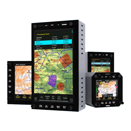
LX Zeus v4.0.2 1.5 Technical specifications LX Zeus 2.8 This version of Zeus can be installed into any standard 80 mm panel cut out and therefore does not require an instrument panel upgrade. Display orientation is only landscape. LX Zeus 2.8 Retrofit Zeus 2.8 Retrofit is the same display size as Zeus 2.8 but differs in hardware. -
Page 12: Part Two - Software
2.1 Display organization and management The available information can be personalised and adjusted to meet the user`s requirements and is set out in the following paragraphs. 2.1.1 Display organization LX Zeus display consists of the following: Geographic map. Bottom row (NavBox line). ... - Page 13 LX Zeus v4.0.2 Compass assistant (assists the pilot when flying with a compass module) Airspace info (information about closest airspace. If no airspace is within selectable limits this indicator is transparent.) Limitations (Start conditions) Map scale AHRS ...
- Page 14 LX Zeus v4.0.2 2.1.1.3 List of available NavBoxes GENERAL SPEED G-force Indicated air speed True air speed Circling radius Ground speed Last full turn time Vario Recommended flaps position Average vario ...
-
Page 15: Setup
LX Zeus v4.0.2 To terminate the process, press the Volume rotary knob (“Go back”). Up to nine bottom rows can be used selectable with 1-4 push buttons. To create a new row simply press 1- 4 and a new row will open. The display configuration may consist of one, two or three NavBox rows. See Setup/Layout for details. -
Page 16: Pilot
(for your information). One can still proceed inside this sector and Zeus will find the optimum position inside the sector to start the new leg. A new leg in statistics will start automatically when the optimum point is reached. - Page 17 To make a user defined warning go to Setup > Pilot select User defined warnings and select “add new”. 1. Then can be defined: o Conditions check frequency (How often Zeus checks if the conditions are fulfilled). o Repeat interval (How often should the warning be repeated).
-
Page 18: Audio
(USB D 60), but settings are stored in LX Zeus. Audio settings do not appear if there is a LX Eos connected to the system. Instead there is a LX Eos icon where the LX Eos can be set up. -
Page 19: Lx Eos
(see previous chapter for more information). If the battery is too empty for the LX Zeus, the LX Eos will still work because it has an internal battery. In this case, settings for LX Eos are set on the LX Eos device (for settings on LX Eos see LX... - Page 20 LX Zeus v4.0.2 Inputs LX Eos offers the possibility of five different user defined inputs. Each input can be set accordingly. There are seven options to choose from: None: nothing is connected to the input. SC: the device changes mode from vario to SC mode ...
-
Page 21: Voice
LX Zeus v4.0.2 LXWPx – sentences contain pressure and altitude information in addition to IAS data PFLAx – Flarm traffic info. Data must be enabled, if Flarm data is required on a PDA Radio – Select which radio is connected to Eos USER port. KRT2 and ATR833 were tested and are supported at the moment. -
Page 22: Vario-Sc
Connect the external switch of input interface, which is connected to the input port on the rear of LX Eos. It does not matter to which of the 5 inputs it is connected. Then go to the Setup page on Zeus and navigate to LX Eos page. - Page 23 *LX Zeus-USB D 60: LX Zeus has a connection for an external speed command switch, which is wired to the vario unit (USB D 60). By using an external switch, it is possible to switch between SC and Vario manually. Setting the External switch mode to ON means that closing the switch will enable SC mode, and setting External switch mode to OFF means that closing the switch will select Vario mode.
-
Page 24: Indicators
One indicator is defined as a variometer. The system is capable of driving secondary indicators identified as ‘’Number 1’’ through to ‘‘Number 4’’. For LX Eos repeater, connect it to Lx Zeus second seat CAN bus port. Upper num. - Page 25 485 bus Once indicator functions have been defined, switch the unit off and then on again, this procedure will memorize the settings and it will then be possible to adjust the settings on LX Zeus. 24 |...
-
Page 26: Flarm
LX Zeus v4.0.2 2.2.8 Flarm This menu is used for changing the Flarm visualisation parameters. The only executive command which can be sent to Flarm unit is privacy mode. Activation of privacy mode will send the Flarm unit into “stealth mode”, which means that the data transmitted to and from Flarm unit is limited. -
Page 27: Logger
LX Zeus v4.0.2 2.2.9 Logger LX Zeus uses LX Eos and/or Colibri II as an IGC approved flight recorder. Both units collaborate so that all necessary settings can be sent to all flight recorders connected to the system (LX Eos, Colibri II). No action is required on LX Eos and Colibri II when flight recorders are connected to LX Zeus. -
Page 28: Airspace
Hide above QNH altitude to disable airspace that is above set QNH altitude • Audio warnings (on vario) when airspace warning appears on the LX Zeus can be dismissed (dismiss buttons) Default warnings for airspace are set to 2 km horizontally and 100 m vertically but these warning settings can be adjusted. -
Page 29: Wind
Position drift calculates wind regarding to position change during circling. Such a method needs more circles than speed difference (from 4 up to 8). The number of circles should be set in Drift circles option. If both methods, straight model and position drift are selected, the Zeus will give a combined result. -
Page 30: Task
LX Zeus v4.0.2 *Compass module is a standalone electronic device, which Note: can be connected to LX Zeus via 485 bus (or CAN bus for Compass option is available newer versions.) The unit delivers the magnetic track to the only if the compass module is LX Zeus. -
Page 31: User Interface
Default: Colour white Size 25 (maximum size can be 60) Map Orientation The map orientation of LX Zeus can be used in three different ways: Track up: Glider always points to the top of the screen ... - Page 32 LX Zeus v4.0.2 Distance circles In this section, it is possible to select the number, size and colour of distance circles on the map. Distance circles are a useful tool for getting a feel about the distance to certain objects on the map.
- Page 33 LX Zeus v4.0.2 2.2.13.3 TP/APT settings In this menu, the appearance and length of TP and APT labels on the map can be adjusted at different zoom levels: Show TP till zoom: Adjust visibility of TP at given zoom ...
- Page 34 LX Zeus v4.0.2 2.2.13.5 Airspace The colours and width of airspace sections to meet personal preferences can be set. Default colours are: Selected/active airspace: Blue Controlled area: Red Prohibited area: Red All other: Blue 2.2.13.6 Tail settings This page is used for adjusting the tail parameters.
- Page 35 Auto close inactivity time out LX Zeus monitors the push buttons and rotary knobs during the editing process. If no action is detected the program will change back to the previously used navigation page after a predefined time period. The time is flexible and can be chosen in a range from 6 to 60 seconds.
- Page 36 LX Zeus v4.0.2 2.2.13.11 Layout The LX Zeus home screen can be customised. Which NavBoxes are shown can be changed as well as their size, order and where they are placed. The same can be done with the map as well as other indicators.
- Page 37 LX Zeus v4.0.2 Moving and resizing How to move selected element: Select indicator to be moved Short press Zoom rotary knob (a large cursor symbol will appear in the middle of the indicator) Use Zoom and Volume rotary knob to move the indicator ...
- Page 38 LX Zeus v4.0.2 2.2.13.12.1 Selecting/Deselecting and editing Editing process: Select the indicator to be customized (a blue frame will appear). LONG press the Zoom rotary knob (if a long press is not made then there will still be an option to...
- Page 39 LX Zeus v4.0.2 Selecting/deselecting process: Go to Setup > Layout, press Zoom rotary knob, select the screen to be edited and go to Edit (press Zoom rotary knob) Make a LONG press on Zoom rotary knob and the window Properties/Actions will open ...
- Page 40 LX Zeus v4.0.2 Properties/Actions window This window is activated by a LONG press of the Zoom rotary knob. In this window, colours can be adjusted for the selected indicator as well as other setting such as: Number of rows for NavBox container ...
- Page 41 LX Zeus v4.0.2 Map – NavBox container transparency If it is required to have a NavBox container transparent, then the map should be stretched over the whole screen and background colour for the NavBox container should be set to transparent.
-
Page 42: System Setup
2.3.2 Glider Nearly all glider polars are stored in the LX Zeus memory. In addition to these standard polars it is possible to create custom polars by changing the parameters. In the glider menu, it is possible to set all glider related information, such as: ... - Page 43 To use these parameters select Use calculated parameters. 3 default polars can be set under Active polar which will appear once the Zeus is turned on. This feature is especially useful for a glider with variable wing span. 2.3.2.2 Speed indicator settings The speed markings of the sliding IAS indicator colours on the Zeus can be adjusted.
- Page 44 Exit this dialog to send the new settings to LX Flaps Sensor. 2.3.2.5 Total Energy (TE) level and filter There are 2 ways of providing TE for the LX Zeus; either tube or electronic compensation. TE level***, set TE compensation style, 0% for TE tube compensation.
- Page 45 The method used is determined by the % figure set for compensation as well as the way in which the pneumatic tubes are connected. If compensation by using a TE probe is required, then set the % figure at 0%. With this method, the Zeus will not process any electronic compensation and will use only the TE source.
- Page 46 LX Zeus v4.0.2 Note! If electronic TE compensation is selected, then the TE (Pst) port should be connected to a good static pressure source. If pneumatic compensation is selected, then the TE (Pst) port should be connected to the TE probe.
-
Page 47: Checklist
A checklist can also be created on a computer which should be quicker. It can be imported via USB key to the LX Zeus. To import/export a checklist go to Setup>Transfer>Checklist. Use Check list editor software for LX Zeus available free on www.lxnavigation.com under the software section. -
Page 48: Notepad
.txt files can be uploaded with the USB stick by pressing the screen button LOAD (button SELECT/NEAR). Notes can be also written directly into the LX Zeus by using the Zoom and Volume rotary knobs. ... - Page 49 A green check means the file is active. How to delete files (APT, TP, AS): Files can be removed from the LX Zeus using the Delete internal files command. The command is executable for Airports, Turn points and Airspace.
- Page 50 Go to task on Zeus (.tsk) Select Copy all tasks from USB This is valid only for Tasks made on LX Zeus, tasks made on SeeYou or Strepla have to be uploaded as TP (TP/Task file) using .cup format. 2.3.5.3 Transfer Airspace files To transfer airspace data, use the Airspace option in the Transfer menu.
- Page 51 Checklists can be prepared on a personal computer using the special PC software available free from the LX Navigation website. Files must be written in .xml format. They can be uploaded into LX Zeus by choosing Checklist (.xml) in this menu. It is also possible to transfer checklists from LX Zeus to USB.
-
Page 52: Service
Level adjustment of units with AHRS. Detected hardware. With the use of admin passwords, the LX Zeus can be set back to factory settings with the password 46486. This will also delete all flights from Colibri II and Eos if they are connected to the system. - Page 53 LX Zeus v4.0.2 2.3.6.2 Crash report Saving a Zeus system crash report to a USB stick can be done by using admin password "27274". If a system crash occurs, please send LX Navigation the file. Once safely on the ground, put a USB stick into the Zeus and use the password in Settings->Service- >Admin password to save crash report to USB key.
- Page 54 LX Zeus v4.0.2 Repeat the LX Zeus level adjustment, but now put the glider in such a position (lift or lower nose or tail wheel) that the pitch on the LX Zeus indicates the same angle as observed during the previous flight.
-
Page 55: Localisation Settings
LX Zeus v4.0.2 2.3.6.6 Radio (KRT2, ATR833) KRT2 or ATR833 radios can be controlled from LX Zeus. It is possible to adjust some functions (this is the dialog available from the shortcuts menu): o Volume o Squelch o Dual: If it is ON the radio listens to 2 frequencies at once. -
Page 56: Brightness
Brightness can be set by pressing the brightness icon in System settings. Note! Not valid for LX Zeus 4.3 and LX Zeus 2.8. They do not have the brightness adjustment option. 55 |... -
Page 57: Navigation Modes
LX Zeus v4.0.2 3 Navigation modes LX Zeus offers three modes for navigation. These modes are: APT: navigation to airports stored in APT memory TP: navigation to turnpoints (TP) TSK: task navigation after task has been entered. -
Page 58: Second Navigation Page
LX Zeus v4.0.2 The bottom row consists of NavBoxes. Bottom rows are selectable by pushing button 1-4. All NavBox positions are customisable by following the simple procedure set out below. Editing NavBox: Give a long press on the Zoom rotary knob (blue frame will appear) ... -
Page 59: Third Navigation Page
3.2 APT mode (navigation to airports) LX Zeus’ airport database is stored in a special .af file format (LX Navigation airport format). Only one .af can be active at the same time. To transfer and/or select new .af file go to Setup>Transfer>Airports. -
Page 60: How To Select An Airport
LX Zeus v4.0.2 The RWY orientation shown matches the real situation. Extended Airport data is available in the lower section of the second subpage. Pressing the 1-4 button on the second subpage will bring up some additional screens (wind profile, thermal history, etc.). -
Page 61: Apt Selection From Near Function
A .cupx file can be prepared on a PC or on LX Zeus. To add pictures to turn-points use Select TP menu. On the bottom of the menu is shown the Upload photo screen button. Use it to transfer pictures from an USB stick to the selected turn-point. - Page 62 LX Zeus v4.0.2 Extended TP data is available in the lower section of the first subpage. The upper part of the display (1 subpage) is vertical terrain profile. To activate the screen buttons for the TP options the Zoom rotary knob should be pressed when on TP screen (not at APT or TSK).
- Page 63 LX Zeus v4.0.2 3.4.1.2 Create User turnpoints User turn-points are turn-points that are created by the pilot on LX Zeus Auto TP If Auto TP is selected, a user TP will be created, with the current position and the current time as its name. To edit an Auto created TP use the Edit TP function.
-
Page 64: Selecting Turn-Points
(press Volume rotary knob) can be used. Important! Turn-points without country designators selectable only when using Country “All” option. This is also valid for user turn-points. Check and correct all files manually before uploading them to LX Zeus. 63 | P a g e... -
Page 65: Uploading Tp Photo
LX Zeus v4.0.2 3.4.2.1 Selection from Near LX Zeus Near function offers Turn-point selection based on distance. It is also uses a Country filter, use All if you want to select from all turn-points. 3.4.3 Uploading TP photo It is possible to upload a photo and assign it to a TP. -
Page 66: Tsk Mode (Navigation On Task)
Task organization Tasks that you want to upload to LX Zeus Zeus has a storing capacity for 100 tasks. 51 tasks can be should be a part of a .cup file and should imported from one .cup file and such tasks are called be selected under SETUP>TRANSFER as... -
Page 67: Task Creation By Hand
LX Zeus v4.0.2 3.5.3 Task creation by hand To create a new task press TSK/MOVE (short press) or give a short press on the Zoom rotary knob if you are on TSK main navigation page. The task can be created by hand by using NEW or EDIT screen buttons. - Page 68 LX Zeus v4.0.2 3.5.3.1 Creating a task in Pan mode It is possible to create a task in Pan mode by following these steps: Press SELECT button on TSK screen Select Pan mode on screen button Navigate to the point on the map using the Zoom/Volume rotary knobs ...
- Page 69 For START and FINISH zones the pilot can select if this zone is a straight line or not. Auto next option enables the Zeus automatically to switch to the next turnpoint once the sector has been reached. This function is active by default if the sector’s radius is below 10 km (racing task). Larger sectors do not have this option as a default.
-
Page 70: Task Functions
LX Zeus v4.0.2 3.5.4 Task Functions Automatic and manual starts are possible by using functions ARM and NEXT TP. All functions are available by pressing the Zoom rotary knob when on the TSK navigation page or by pressing the TSK/MOVE button on other pages. - Page 71 3.5.4.4 Saving TSK to USB LX Zeus offers the option to save created or edited tasks to a USB. A USB stick has to be inserted into the USB port. After the creation of a Task, press the Volume rotary knob to get out of edit menu and declare the task.
-
Page 72: Move Function (During Flight)
To use this feature there are three NavBoxes available on LX Zeus (TEAM CODE, TEAM BEARING and TEAM DISTANCE). Before sending a position with the team code all partners should use same reference turn-point. For better... -
Page 73: Task Zoom
LX Zeus v4.0.2 3.5.6 Task Zoom By rotating the Zoom rotary knob to the left the Task zoom will be activated which will show the whole task on the screen. Task zoom will show all turn-points (moved and modified) with airspace. Task zoom is not visible while flying, only on the ground. -
Page 74: Airspace Management
LX Zeus v4.0.2 4 Airspace Management Airspace on LX Zeus can be managed by the pilot to achieve the optimum relationship between loading the display and its readability. Too much information will reduce the readability of the display. Basic airspace settings Settings are available under Setup >... - Page 75 LX Zeus v4.0.2 4.1.3.1 If set to disabled ( ) the airspace info box for this airspace type will not appear on the screen. Setting checked ( ) will produce airspace info box information. The airspace info box is an indicator on the main screen.
-
Page 76: Disabling Airspace Sections
LX Zeus v4.0.2 4.1.4 Disabling airspace sections During flight, airspace warnings may appear on the screen (picture on the right). Pressing on one of the screen buttons can easily disable the warning. Airspace warnings can be disabled for specific amounts of time (5 minutes, 10 minutes, 30 minutes, 1 hour, 3 hours or for whole day). -
Page 77: Gps Signal Management
5.4 GPS signal for navigation All GPS inputs are used on LX Zeus. This means that LX Zeus is supplied with valid GPS signal as long as at least one connected GPS receiver delivers valid data. A symbol positioned in the right upper corner of the display shows GPS signal status: ... -
Page 78: Lx Zeus And Lx Eos/Era
When LX Eos/Era and LX Zeus are connected, the setup screen cannot be seen on LX Eos/Era, because the setup is done on LX Zeus. If the main power supply fails (ie.: Zeus does not work anymore), and it is still in flight mode, LX Eos/Era will keep working as it has an integrated battery with about a three hour duration. -
Page 79: Lx Eos/Era - Zeus Interaction
LX Zeus v4.0.2 6.2 LX Eos/Era – Zeus interaction After connection between LX Eos/Era and LX Zeus is established, both units will start to communicate over the CAN bus. The connection is established automatically without any pilot interaction. 6.2.1 Commands and declaration transfer to LX Eos/Era... -
Page 80: Lx Zeus And Colibri Ii
LX Eos and LX Zeus together create a very compact and robust system. All flight recording related settings are sent from LX Zeus and, in their relationship, LX Zeus is the master and Colibri II is a slave. This is why it is possible to install Colibri II in an inaccessable place (under/inside instrument panel), as long as the Colibri II position ensures good GPS reception. -
Page 81: Lx Zeus And Flarm
Mini Box) On the rear of the LX Zeus 5.5 and 7.0 there is enough space to install LX Flarm Red Box as an integral part of the system. All connections are plug and play. It is also possible to install any other Flarm compatible devices. -
Page 82: Flarm External Displays
SD port, on the front of the unit (in case of LX Flarm Red Box). After the flight is completed, wait for around three minutes, then turn LX Zeus OFF and ON again. After switching on, a red POWER LED light on the Flarm display starts blinking. -
Page 83: Lx Flarm Redbox / Lx Flarm Minibox Update
8.5 Flarm PINOUT 9 LX Zeus and Garrecht Garrecht units can be connected to LX Zeus using supplied cables. A declaration to Flarm will be sent directly from LX Zeus. Updating Garrecht units is not possible via LX Zeus. The connection schematic is shown below. -
Page 84: Lx Remote Stick
10 LX Remote Stick LX Zeus can be controlled with a LX Remote Stick. The stick is a standard LX Navigation product, which does not differ significantly from sticks used by LX 7000/7007. Therefore, the upgrade of an existing stick is very easy. -
Page 85: Lx Joy
(If the glider type is specified when ordering LXN will know what size is required) NOTE!! In order for LX Zeus to work with LX Joy, the software version on LX Zeus should be at least 3.2.2 or higher. 11.2 Button description... - Page 86 LX Zeus v4.0.2 LX Joy middle button: SELECT Press: ENTER SUBP ZOOM/VOLUME MODE (LED GREEN) Short press: FLARM Short press: FN Long Press: / Long Press: / Short press: ESC Short press: STAT Long Press: / Long Press: / Short press: PTT...
- Page 87 LX Zeus v4.0.2 LX Joy middle button: ZOOM OUT VOLUME - VOLUME + Press: ENTER ZOOM IN PAN MODE (LED RED) Short press: FN Short press: ZOOM IN Long Press: / Long Press: / Short press: ESC Short press: ZOOM OUT...
- Page 88 LX Zeus v4.0.2 LX Joy middle button: Move up Move left Move right Press: GO TO Move down 87 | P a g e...
-
Page 89: Second Seat Unit
The function of the vario indicator connected to the second seat unit should be defined under Setup > Indicators on second seat LX Zeus. Indicators (upper and lower indicator) on the second seat vario can be adjusted from the LX Zeus second seat. Automatic SC switching and external switch mode cannot be adjusted from the second seat unit. -
Page 90: Connecting Lx Eos Repeater To Lx Zeus On Second Seat
11.3 Connecting LX Eos repeater to LX Zeus on second seat To connect a LX Eos repeater to a LX Zeus in the second seat, simply connect units with the CAN cable, which is supplied with LX Eos repeater unit, using the CAN ports on both units. -
Page 91: Part Three - Flying
LX Zeus v4.0.2 PART THREE – Flying 12 Flying with LX Zeus It is recommended that the unit is set up for every flight before take-off to ensure a stress-free and enjoyable flight. This is especially important before any contest, record attempt or badge flight. - Page 92 (main) seat unit. Once the elevation has been entered, LX Zeus will suggest that the current QNH value be used. If the User knows the QNH of the day it should be entered. If not, then an approximate value should be entered. QNH can be changed by pressing the VARIO button.
-
Page 93: During Flight
Declaration to LX Eos/Era, Colibri Declaration to flarm 12.2 During flight The LX Zeus HW and SW concept is combined in such a way that pilot input during flight is cut down to the minimum, enabling the pilot to give full attention to piloting. -
Page 94: Set Maccready (Mc), Ballast, Bugs And Qnh
LX Zeus v4.0.2 12.2.1 Set MacCready (MC), Ballast, Bugs and QNH After a short press on the VARIO button a new window will appear – MacCready. The menu will give options, to adjust MacCready (MC), Ballast, Bugs and QNH. Setting... - Page 95 LX Zeus v4.0.2 End Flight function will close the flight so don’t use it during flight. Once End Flight has been commanded the flight will end and the flight recorder (LX Eos/Era and Colibri II) will be forced to stop flight recording and create an IGC file.
- Page 96 LX Zeus v4.0.2 12.2.2.2 OLC Calculation OLC calculation is a calculation of OLC points according to OLC rules. The current rules can be checked at: http://www.onlinecontest.org/olc-2.0/gliding/cms.html?url=rules In general, the scoring software selects a departure point within the unpowered part of the flight with up to 5 waypoints (turn-points)
-
Page 97: Follow Me
LX Zeus v4.0.2 12.2.2.5 Route Route option is a feature showing the track already flown and the current task on the map. This enables the pilot to see how precise the flying was and where detours were made. 12.2.2.6 Timer To use a stopwatch, the timer function can be used which is located in Statistics. - Page 98 LX Zeus v4.0.2 12.2.4.2 Marker setting If the pilot wants to mark a position of interest, for example a suitable out-landing place, thermal hot spot…), this can be done by activating the Marker function. The process is very simple and doesn’t require much attention by the pilot.
-
Page 99: Task Start
LX Zeus v4.0.2 12.2.4.3 Pan mode It is possible to move the position on the map using the Volume and Zoom rotary knobs. Pan mode is available on all three navigation pages (TP/APT/TSK). During the flight, the tail and Flarm objects are displayed on the map in pan mode. - Page 100 NEXT TP function will solve the problem. Navigation to the first turn point will then be offered and the statistics page will become available. LX Zeus will find last valid start line- cross and use it for statistics. 12.2.5.1 Start Conditions / Limitations...
-
Page 101: Task Finish
LX Zeus v4.0.2 12.2.5.3 Restart Leg Restarting a leg is possible during an active leg. After pressing the TSK/MOVE button the screen button Restart leg will be displayed. 12.2.6 Task Finish A Task finish will be detected after the glider has passed the finish line / cylinder. The event will be displayed by a very clear message showing the achieved task speed. -
Page 102: Final Glide (Fg) Calculation
12.2.9 Finish line crossing In some competitions, long finish lines or finish cylinders may be stipulated. LX Zeus is continuously calculating all parameters and statistics based on the shortest way to reach the finish and therefore it offers the shortest distance to reach it. This distance is used in all calculations (FG, TDT, etc.). -
Page 103: Flarm Management
VARIO/FLARM push button. There is no limit to the number of Flarm objects displayed on LX Zeus. A default colour can be set in Settings > Flarm. There are some additional settings that are related to displaying Flarm objects on the map. -
Page 104: Attitude And Heading Reference System (Ahrs)
Attitude and heading reference system (AHRS) An artificial horizon (AHRS) box can be connected to LX Zeus simply by connecting it via a CAN cable (Plug and Play). It can be connected to the first or second seat LX Zeus. -
Page 105: After Landing
12.3 After landing The Zeus should be kept ON for a few minutes after landing in order to ensure that a baseline for the baro trace is generated. There will be a small window showing: Flight will end in xx:yy this being the time left until the flight recorder stops recording. - Page 106 SD card after next power on. So, power LX Zeus off and on to download the latest flight. It is suggested that the SD card is kept in the LX Zeus SD slot all the time in order to avoid long waiting times from the downloading of many flights that are not yet on the SD card.
-
Page 107: Icao Charts
This will not happen, though, if LX Eos/Era or Colibri II are in flight mode while running on internal battery. Note! If LX Zeus loses power during flight this will not switch off LX Eos/Era or Colibri II. The IGC flight recorder has an internal backup battery for such occasions. 12.4 ICAO charts LX Zeus offers the use of ICAO charts from Rogersdata and Deutsche Flugsicherung. -
Page 108: Part Four - Miscellaneous
Flaps sensor calibration. 13.2 Electrical installation 13.2.1 LX Zeus with Vario (USB-D 60) This part of the installation is easy and doesn’t require any specialists. The system receives its power via two power lines, which should be connected to 12V glider power source and ground. The red wire is 12V and blue wire is Ground. - Page 109 The 9P connector should be inserted into any free 485-marked plug on LX Zeus back. The unit receives power from LX Zeus. Speaker output is terminated with one chinch female connector. A male chinch connector is part of the speaker delivery.
- Page 110 LX Zeus v4.0.2 13.2.1.2 USB-D 60 wiring 109 | P a g e...
-
Page 111: Installation Of Second Seat Units
LX Zeus v4.0.2 13.3 Installation of second seat units The second seat unit shares the same logic as the master LX Zeus. There is no difference in mechanical installation. 13.3.1 Electrical installation The second seat unit doesn’t need external power as it is powered via the system bus (CAN). For CAN connection two 8P connectors are provided on both the master and the repeater. -
Page 112: Explanation Of Navbox Terms
LX Zeus v4.0.2 14 Explanation of NavBox terms NAV BOX Item Description designator Above ground level Altitude above ground level Air temperature Temp Altitude IGC Altitude recorded by flight recorder (1013 based) Alt IGC Altitude GPS Altitude recorded by GPS... - Page 113 LX Zeus v4.0.2 ETA (current speed) Estimated time of arrival based on actual speed ETA Sp ETA MacCready speed ETA based on MC setting ETA MC Final glide Altitude difference related to f.g. line Final glide (MC 0.0) Altitude difference related to f.g. line at MC 0.0 FG(MC 0.0)
- Page 114 Momentary variometer value Vario Vertical distance from Glider position vertically from the airspace AS ver airspace Wind direction Wind direction calculated by Zeus Wind Dir Wind speed Wind speed calculated by Zeus Wind Sp 113 | P a g e...
-
Page 115: Faq (Frequently Asked Questions)
The voice module will also give voice-warnings for airspaces. 9. ENL and Zeus? If an IGC Zeus is ordered, then the ENL sensor is the part of the system without charge (built in Colibri II, LX Eos) 10. AHRS – is it adjustable so that it can be set on the ground? Yes, of course. - Page 116 Unit on my double seater, what can I do? First check that the Zeus units are connected. This is done by a long press on Setup/info button. In the Info window, there should be a sign either primary unit or secondary unit.
- Page 117 LX Zeus v4.0.2 116 | P a g e...
Need help?
Do you have a question about the Zeus and is the answer not in the manual?
Questions and answers